EP1995843A2 - Dispositif de stockage d'énergie pour véhicules automobiles - Google Patents
Dispositif de stockage d'énergie pour véhicules automobiles Download PDFInfo
- Publication number
- EP1995843A2 EP1995843A2 EP08103616A EP08103616A EP1995843A2 EP 1995843 A2 EP1995843 A2 EP 1995843A2 EP 08103616 A EP08103616 A EP 08103616A EP 08103616 A EP08103616 A EP 08103616A EP 1995843 A2 EP1995843 A2 EP 1995843A2
- Authority
- EP
- European Patent Office
- Prior art keywords
- memory arrangement
- energy
- electrical
- voltage
- arrangement according
- Prior art date
- Legal status (The legal status is an assumption and is not a legal conclusion. Google has not performed a legal analysis and makes no representation as to the accuracy of the status listed.)
- Granted
Links
Images


Classifications
-
- H—ELECTRICITY
- H02—GENERATION; CONVERSION OR DISTRIBUTION OF ELECTRIC POWER
- H02J—ELECTRIC POWER NETWORKS; CIRCUIT ARRANGEMENTS OR SYSTEMS FOR SUPPLYING OR DISTRIBUTING ELECTRIC POWER; SYSTEMS FOR STORING ELECTRIC ENERGY
- H02J7/00—Circuit arrangements for charging or discharging batteries or for supplying loads from batteries
- H02J7/14—Circuit arrangements for charging or discharging batteries or for supplying loads from batteries for charging batteries from dynamo-electric generators driven at varying speed, e.g. on vehicle
- H02J7/1423—Circuit arrangements for charging or discharging batteries or for supplying loads from batteries for charging batteries from dynamo-electric generators driven at varying speed, e.g. on vehicle with multiple batteries
-
- H—ELECTRICITY
- H02—GENERATION; CONVERSION OR DISTRIBUTION OF ELECTRIC POWER
- H02J—ELECTRIC POWER NETWORKS; CIRCUIT ARRANGEMENTS OR SYSTEMS FOR SUPPLYING OR DISTRIBUTING ELECTRIC POWER; SYSTEMS FOR STORING ELECTRIC ENERGY
- H02J7/00—Circuit arrangements for charging or discharging batteries or for supplying loads from batteries
- H02J7/14—Circuit arrangements for charging or discharging batteries or for supplying loads from batteries for charging batteries from dynamo-electric generators driven at varying speed, e.g. on vehicle
- H02J7/1438—Circuit arrangements for charging or discharging batteries or for supplying loads from batteries for charging batteries from dynamo-electric generators driven at varying speed, e.g. on vehicle in combination with power supplies for loads other than batteries
-
- H—ELECTRICITY
- H02—GENERATION; CONVERSION OR DISTRIBUTION OF ELECTRIC POWER
- H02J—ELECTRIC POWER NETWORKS; CIRCUIT ARRANGEMENTS OR SYSTEMS FOR SUPPLYING OR DISTRIBUTING ELECTRIC POWER; SYSTEMS FOR STORING ELECTRIC ENERGY
- H02J7/00—Circuit arrangements for charging or discharging batteries or for supplying loads from batteries
- H02J7/14—Circuit arrangements for charging or discharging batteries or for supplying loads from batteries for charging batteries from dynamo-electric generators driven at varying speed, e.g. on vehicle
- H02J7/1446—Circuit arrangements for charging or discharging batteries or for supplying loads from batteries for charging batteries from dynamo-electric generators driven at varying speed, e.g. on vehicle in response to parameters of a vehicle
-
- H—ELECTRICITY
- H02—GENERATION; CONVERSION OR DISTRIBUTION OF ELECTRIC POWER
- H02J—ELECTRIC POWER NETWORKS; CIRCUIT ARRANGEMENTS OR SYSTEMS FOR SUPPLYING OR DISTRIBUTING ELECTRIC POWER; SYSTEMS FOR STORING ELECTRIC ENERGY
- H02J7/00—Circuit arrangements for charging or discharging batteries or for supplying loads from batteries
- H02J7/34—Parallel operation in networks using both storage and other DC sources, e.g. providing buffering
- H02J7/345—Parallel operation in networks using both storage and other DC sources, e.g. providing buffering using capacitors as storage or buffering devices
-
- H—ELECTRICITY
- H02—GENERATION; CONVERSION OR DISTRIBUTION OF ELECTRIC POWER
- H02J—ELECTRIC POWER NETWORKS; CIRCUIT ARRANGEMENTS OR SYSTEMS FOR SUPPLYING OR DISTRIBUTING ELECTRIC POWER; SYSTEMS FOR STORING ELECTRIC ENERGY
- H02J2207/00—Details of circuit arrangements for charging or discharging batteries or supplying loads from batteries
- H02J2207/20—Charging or discharging characterised by the power electronics converter
-
- Y—GENERAL TAGGING OF NEW TECHNOLOGICAL DEVELOPMENTS; GENERAL TAGGING OF CROSS-SECTIONAL TECHNOLOGIES SPANNING OVER SEVERAL SECTIONS OF THE IPC; TECHNICAL SUBJECTS COVERED BY FORMER USPC CROSS-REFERENCE ART COLLECTIONS [XRACs] AND DIGESTS
- Y02—TECHNOLOGIES OR APPLICATIONS FOR MITIGATION OR ADAPTATION AGAINST CLIMATE CHANGE
- Y02T—CLIMATE CHANGE MITIGATION TECHNOLOGIES RELATED TO TRANSPORTATION
- Y02T10/00—Road transport of goods or passengers
- Y02T10/60—Other road transportation technologies with climate change mitigation effect
- Y02T10/70—Energy storage systems for electromobility, e.g. batteries
-
- Y—GENERAL TAGGING OF NEW TECHNOLOGICAL DEVELOPMENTS; GENERAL TAGGING OF CROSS-SECTIONAL TECHNOLOGIES SPANNING OVER SEVERAL SECTIONS OF THE IPC; TECHNICAL SUBJECTS COVERED BY FORMER USPC CROSS-REFERENCE ART COLLECTIONS [XRACs] AND DIGESTS
- Y02—TECHNOLOGIES OR APPLICATIONS FOR MITIGATION OR ADAPTATION AGAINST CLIMATE CHANGE
- Y02T—CLIMATE CHANGE MITIGATION TECHNOLOGIES RELATED TO TRANSPORTATION
- Y02T10/00—Road transport of goods or passengers
- Y02T10/80—Technologies aiming to reduce greenhouse gasses emissions common to all road transportation technologies
- Y02T10/92—Energy efficient charging or discharging systems for batteries, ultracapacitors, supercapacitors or double-layer capacitors specially adapted for vehicles
Definitions
- the invention relates to a memory arrangement for electrical energy for motor vehicles with an electrical system having an energy storage, an input and an output, wherein the memory device is suitable and designed to record via the input of electrical energy from the electrical system for storage in the energy storage and the output to release electrical energy taken from the energy store to a part of the electrical system that can be connected to the output (U2out).
- the invention further relates to a vehicle electrical system in motor vehicles with at least one safety-relevant consumer, in particular an X-by-wire system with a starter battery or vehicle battery and with a memory arrangement for electrical energy, wherein the memory device is suitable and adapted in case of failure of a generator and / or the starter battery or vehicle battery to provide the energy for the safety-relevant consumer.
- the safety-relevant consumers are therefore connected to the output of the memory array.
- X-by-wire functions require that the supply of the electric control devices, sensors, etc. assigned to these functions be redundantly designed with electrical energy, so that the function will function in the event of a power failure, for example as a result of a defective vehicle battery or a defective one Generator, is not affected. It must then be ensured that the redundant energy source is able to deliver a defined amount of electrical energy and to provide it within a defined time according to a defined load profile. In addition, it must be able to maintain the necessary for the function of the X-by-wire component voltages in the connected to the output part of the electrical system, ie usually to guarantee a voltage of at least 9 volts in the part.
- the double-layer capacitors can not completely emit the electrical energy stored in them, which represents a further disadvantage of the double-layer capacitors.
- a large space in the motor vehicle is necessary for the installation of a series connection of a plurality of double-layer capacitors, which can not be provided or only to a very limited extent.
- the present invention therefore an object of the invention to improve a memory device of the type mentioned so that a simpler maintenance and monitoring of the energy storage device is possible.
- the battery maintenance-free energy storage system in contrast to the battery maintenance-free energy storage system to be created.
- the representable voltage level associated therewith should not be limiting.
- the memory array has at least one electrical voltage converter, which is suitable for the transport of electrical energy between the input and / or the output on the one hand and the energy storage on the other hand.
- a vehicle electrical system of the type mentioned can have such a memory arrangement.
- the advantage of a memory arrangement according to the invention or an electrical system with a memory arrangement according to the invention is that the energy store can be operated independently of the rated voltage or minimum voltage in the electrical system.
- the energy store can be operated independently of the rated voltage or minimum voltage in the electrical system.
- this makes it possible to use a single double-layer capacitor without having to connect it in series with identical double-layer capacitors.
- the installation space, which otherwise usually had to be provided for the series circuits of double-layer capacitors used, is not absolutely necessary for a memory arrangement of the type according to the invention.
- the rated voltage at the input and / or output of the memory device i. H. the rated voltage of the electrical system is greater than the rated voltage of the energy storage.
- a memory arrangement can have a two-quadrant or a multi-quadrant controller, which is used to convert the voltage and to transport the electrical energy from or to the energy store. It can be a bidirectional synchronous buck / boost converter.
- the single-quadrant controllers may be step-down converters and boost converters.
- the buck converter connects the input of the memory array with the energy storage and the boost converter connects the energy storage to the output of the memory array.
- a single Einquadrantensteller is used as an electrical voltage converter.
- it may be, for example, an inverting inhibitor.
- the memory arrangement may comprise means for controlling the voltage converter (s).
- means for examining the state of the energy storage device can be provided which report the status of the energy storage device to a central control device of the storage arrangement or of the vehicle electrical system.
- a memory arrangement according to the invention can have means for protecting the energy store against overvoltages and / or short circuits.
- the energy store may be an accumulator, i. H. to trade a conventional vehicle battery.
- the advantages of the memory device according to the invention are particularly effective when using a double-layer capacitor as energy storage.
- a memory device comprises means for detecting the input voltage of the memory device, i. H. the electrical system voltage on.
- the means for detecting the input voltage may be suitable and configured, in the event of a failure of the vehicle electrical system voltage and / or a drop below the mains voltage of the electrical system by the vehicle electrical system voltage by a predetermined amount transport of electrical energy from the energy storage in the connected to the output part of the electrical system with the security-relevant consumers.
- the electrical system according to the invention Fig. 1 has a generator G which is connected to a starter battery 1 and to an input U2 in a memory arrangement 2 according to the invention via a line 11. Likewise, the generator output is connected to various consumers, in particular via a line 13 to the input V1 of a safety-relevant consumer. 3
- the memory arrangement 2 has an energy store 2a.
- the latter absorbs the electrical energy transported via the input U2 in the energy storage arrangement 2 to the storage arrangement.
- the memory arrangement is further connected to the ground potential of the motor vehicle.
- the generator G In trouble-free operation, electrical energy is provided via the generator G. This is fed into the starter battery 1 and made available to consumers, including the safety-relevant consumer 3. At the same time, the energy storage device 2 removes electrical power from the vehicle electrical system until the energy storage device 2a is charged. Furthermore, it is ensured that the energy storage device 2a remains charged if, in the case of a self-discharge, the voltage of the energy storage device 2a should decrease.
- the energy storage device 2 ensures that at its output U2aus, which is connected via the connecting element 12 to the second, redundant supply input V2 of the safety-relevant consumer 3, the voltage level in remains defined area, a sufficient amount of energy is provided and the required load profile can be met.
- the failure in particular of the starter battery 1 can be determined that the memory device 2 according to the invention monitors the value of the input voltage U2ein.
- the behavior of the memory array 2 and the provision of electrical energy at the output U2 from the memory array can be adapted to the particular application. It is conceivable that the output U2aus is supplied with electrical energy only when the failure of the starter battery is detected. Alternatively, it is conceivable that energy is temporarily made available at the output U2 from the memory arrangement, at least even if the starter battery functions regularly. The latter can be used as a possibility for diagnosing the memory arrangement 2. Monitoring electronics, for example in the safety-relevant consumer 3, could in this case close the state of the energy store 2 a by evaluating the behavior of the memory arrangement 2. A regular review of the memory array 2, especially in safety-relevant systems is namely recommended and sometimes even necessary.
- Fig. 2 is used as a voltage converter buck converter 1 and a boost converter 2, wherein the buck converter converter 1 between the input U2ein and the energy storage 2a and the boost converter 2 is connected between the energy storage 2a and the output U2off.
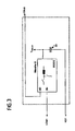
- a bidirectional voltage transformer is used in the memory array converter 3 according to Fig. 3 .
- This may be, for example, a synchronous buck / boost converter, which in Fig. 2 is shown schematically.
- the use of a buck / boost transducer is advantageous because fewer components are required.
- the input and the output of the buck / boost converter are decoupled in this embodiment in terms of their energy flow direction, which is represented by the two diodes indicated.
Landscapes
- Engineering & Computer Science (AREA)
- Power Engineering (AREA)
- Charge And Discharge Circuits For Batteries Or The Like (AREA)
- Electric Propulsion And Braking For Vehicles (AREA)
Applications Claiming Priority (1)
| Application Number | Priority Date | Filing Date | Title |
|---|---|---|---|
| DE102007018987A DE102007018987A1 (de) | 2007-04-21 | 2007-04-21 | Energiespeicheranordnung für Kraftfahrzeuge |
Publications (3)
| Publication Number | Publication Date |
|---|---|
| EP1995843A2 true EP1995843A2 (fr) | 2008-11-26 |
| EP1995843A3 EP1995843A3 (fr) | 2014-12-31 |
| EP1995843B1 EP1995843B1 (fr) | 2016-01-06 |
Family
ID=39731442
Family Applications (1)
| Application Number | Title | Priority Date | Filing Date |
|---|---|---|---|
| EP08103616.2A Active EP1995843B1 (fr) | 2007-04-21 | 2008-04-18 | Dispositif de stockage d'énergie pour véhicules automobiles |
Country Status (2)
| Country | Link |
|---|---|
| EP (1) | EP1995843B1 (fr) |
| DE (1) | DE102007018987A1 (fr) |
Cited By (1)
| Publication number | Priority date | Publication date | Assignee | Title |
|---|---|---|---|---|
| DE102014100310A1 (de) | 2014-01-13 | 2015-07-16 | Hella Kgaa Hueck & Co. | Speicheranordnung für elektrische Energie für ein Kraftfahrzeug |
Families Citing this family (1)
| Publication number | Priority date | Publication date | Assignee | Title |
|---|---|---|---|---|
| FR3141918A1 (fr) * | 2022-11-10 | 2024-05-17 | Psa Automobiles Sa | Alimentation sécurisée d’organes de direction assistée électrique pour véhicule automobile |
Family Cites Families (7)
| Publication number | Priority date | Publication date | Assignee | Title |
|---|---|---|---|---|
| JPH05276689A (ja) * | 1992-03-24 | 1993-10-22 | Toshiba Corp | 無停電電源システム |
| JP2861676B2 (ja) * | 1992-08-31 | 1999-02-24 | 日本精機株式会社 | 車両用計器 |
| DE19859036A1 (de) * | 1998-12-24 | 2000-06-29 | Audi Ag | Bordnetz für ein Kraftfahrzeug |
| EP1360090B1 (fr) * | 2001-02-16 | 2005-01-12 | Siemens Aktiengesellschaft | Reseau de bord de vehicule automobile |
| JP4306534B2 (ja) * | 2004-05-25 | 2009-08-05 | 株式会社デンソー | 乗員保護装置 |
| DE102004000035A1 (de) * | 2004-10-29 | 2006-05-04 | Ford Global Technologies, LLC, A Subsidiary of Ford Motor Company, Dearborn | Diagnoseverfahren zur Bestimmung des Alterungszustandes eines Kondensators |
| DE102005008719A1 (de) * | 2005-02-25 | 2006-09-14 | Robert Bosch Gmbh | Energieversorgungssystem |
-
2007
- 2007-04-21 DE DE102007018987A patent/DE102007018987A1/de not_active Withdrawn
-
2008
- 2008-04-18 EP EP08103616.2A patent/EP1995843B1/fr active Active
Cited By (1)
| Publication number | Priority date | Publication date | Assignee | Title |
|---|---|---|---|---|
| DE102014100310A1 (de) | 2014-01-13 | 2015-07-16 | Hella Kgaa Hueck & Co. | Speicheranordnung für elektrische Energie für ein Kraftfahrzeug |
Also Published As
| Publication number | Publication date |
|---|---|
| EP1995843A3 (fr) | 2014-12-31 |
| EP1995843B1 (fr) | 2016-01-06 |
| DE102007018987A1 (de) | 2008-10-23 |
Similar Documents
| Publication | Publication Date | Title |
|---|---|---|
| DE102013106854B4 (de) | Schaltung zur Einschaltstrombegrenzung | |
| EP2440432B1 (fr) | Circuit et méthode de commande pour rupport du tension dans un réseau de bord d'un véhicule | |
| DE102011086264B4 (de) | Elektronische Fahrzeugsteuervorrichtung | |
| DE112008003996T5 (de) | Treibereinheit | |
| DE102017114339A1 (de) | Sichere Energieversorgungseinrichtung für ein Fahrzeug | |
| DE102014008516A1 (de) | Bordnetz für ein Kraftfahrzeug | |
| EP3239517B1 (fr) | Dispositif de commande d'une circulation de courant dans un réseau de distribution de bord d'un véhicule | |
| DE102006010713A1 (de) | Bordnetz für ein Fahrzeug und Verfahren zur Energieversorgung eines sicherheitsrelevanten Verbrauchers eines Bordnetzes | |
| DE102012208520A1 (de) | Vorrichtung und Verfahren zur Verbindung von Mehrspannungsbordnetzen | |
| DE10348162B3 (de) | Vorrichtung zur redundanten Energieversorgung sicherheitsrelevanter Verbraucher | |
| DE102017204065A1 (de) | Antriebssystem für ein Fahrzeug und Verfahren zum Betrieb eines Antriebssystems | |
| DE112022003328T5 (de) | Stromversorgungsvorrichtung und elektroantriebsvorrichtung | |
| DE102018212351A1 (de) | Verfahren zur Diagnose eines Schaltmittels in einem Kraftfahrzeug | |
| DE102012007225A1 (de) | Energieversorgungssystem, insbesondere für ein Kraftfahrzeug | |
| EP1641650A1 (fr) | Limiteur de surtension concu pour un convertisseur de courant de traction | |
| DE102011105971B4 (de) | Bordnetzanordnung für ein Kraftfahrzeug | |
| DE10218669A1 (de) | Brennstoffzellensystem und Verfahren zur Spannungsüberwachung für ein Brennstoffzellensystem | |
| DE102013104139A1 (de) | Verfahren und Vorrichtung zur Inbetriebnahme eines Feldgerätes | |
| EP3197726B1 (fr) | Réseau de bord | |
| DE102017221621A1 (de) | Vorrichtung zur redundanten Energieversorgung zumindest eines Verbrauchers eines Kraftfahrzeugs aus einem Bordnetz, Bordnetz sowie Kraftfahrzeug | |
| EP2553257A1 (fr) | Réseau de bord pour véhicule et dispositif de commande pour réguler un flux de courant dans un réseau de bord de véhicule | |
| DE102016224618A1 (de) | Fahrzeug-Bordnetz mit hoher Verfügbarkeit | |
| EP1995843B1 (fr) | Dispositif de stockage d'énergie pour véhicules automobiles | |
| DE102018212353A1 (de) | Vorrichtung zur Energieversorgung, insbesondere eines Kraftfahrzeugs mit automatisierter Fahrfunktion | |
| DE10324250B4 (de) | Spannungsversorgungssystem für sicherheitsrelevante elektrische Verbraucher |
Legal Events
| Date | Code | Title | Description |
|---|---|---|---|
| PUAI | Public reference made under article 153(3) epc to a published international application that has entered the european phase |
Free format text: ORIGINAL CODE: 0009012 |
|
| AK | Designated contracting states |
Kind code of ref document: A2 Designated state(s): AT BE BG CH CY CZ DE DK EE ES FI FR GB GR HR HU IE IS IT LI LT LU LV MC MT NL NO PL PT RO SE SI SK TR |
|
| AX | Request for extension of the european patent |
Extension state: AL BA MK RS |
|
| PUAL | Search report despatched |
Free format text: ORIGINAL CODE: 0009013 |
|
| AK | Designated contracting states |
Kind code of ref document: A3 Designated state(s): AT BE BG CH CY CZ DE DK EE ES FI FR GB GR HR HU IE IS IT LI LT LU LV MC MT NL NO PL PT RO SE SI SK TR |
|
| AX | Request for extension of the european patent |
Extension state: AL BA MK RS |
|
| RIC1 | Information provided on ipc code assigned before grant |
Ipc: H02J 7/14 20060101AFI20141126BHEP Ipc: H02M 3/158 20060101ALI20141126BHEP Ipc: H02J 7/34 20060101ALI20141126BHEP Ipc: H02J 7/00 20060101ALI20141126BHEP |
|
| 17P | Request for examination filed |
Effective date: 20150428 |
|
| RBV | Designated contracting states (corrected) |
Designated state(s): AT BE BG CH CY CZ DE DK EE ES FI FR GB GR HR HU IE IS IT LI LT LU LV MC MT NL NO PL PT RO SE SI SK TR |
|
| GRAP | Despatch of communication of intention to grant a patent |
Free format text: ORIGINAL CODE: EPIDOSNIGR1 |
|
| GRAJ | Information related to disapproval of communication of intention to grant by the applicant or resumption of examination proceedings by the epo deleted |
Free format text: ORIGINAL CODE: EPIDOSDIGR1 |
|
| GRAP | Despatch of communication of intention to grant a patent |
Free format text: ORIGINAL CODE: EPIDOSNIGR1 |
|
| AKX | Designation fees paid |
Designated state(s): AT BE BG CH CY LI |
|
| AXX | Extension fees paid |
Extension state: AL Extension state: MK Extension state: BA Extension state: RS |
|
| REG | Reference to a national code |
Ref country code: DE Ref legal event code: R108 Ref document number: 502008013712 Country of ref document: DE Ref country code: DE Ref legal event code: R108 |
|
| INTG | Intention to grant announced |
Effective date: 20150814 |
|
| RBV | Designated contracting states (corrected) |
Designated state(s): AT BE BG CH CY CZ LI |
|
| INTG | Intention to grant announced |
Effective date: 20150831 |
|
| RBV | Designated contracting states (corrected) |
Designated state(s): AT BE BG CH CY CZ DE DK EE ES FI FR GB GR HR HU IE IS IT LI LT LU LV MC MT NL NO PL PT RO SE SI SK TR |
|
| GRAS | Grant fee paid |
Free format text: ORIGINAL CODE: EPIDOSNIGR3 |
|
| GRAA | (expected) grant |
Free format text: ORIGINAL CODE: 0009210 |
|
| AK | Designated contracting states |
Kind code of ref document: B1 Designated state(s): AT BE BG CH CY CZ DE DK EE ES FI FR GB GR HR HU IE IS IT LI LT LU LV MC MT NL NO PL PT RO SE SI SK TR |
|
| REG | Reference to a national code |
Ref country code: GB Ref legal event code: FG4D Free format text: NOT ENGLISH |
|
| REG | Reference to a national code |
Ref country code: CH Ref legal event code: EP |
|
| REG | Reference to a national code |
Ref country code: IE Ref legal event code: FG4D Free format text: LANGUAGE OF EP DOCUMENT: GERMAN |
|
| REG | Reference to a national code |
Ref country code: AT Ref legal event code: REF Ref document number: 769604 Country of ref document: AT Kind code of ref document: T Effective date: 20160215 |
|
| REG | Reference to a national code |
Ref country code: DE Ref legal event code: R096 Ref document number: 502008013712 Country of ref document: DE |
|
| REG | Reference to a national code |
Ref country code: FR Ref legal event code: PLFP Year of fee payment: 9 |
|
| REG | Reference to a national code |
Ref country code: LT Ref legal event code: MG4D |
|
| REG | Reference to a national code |
Ref country code: NL Ref legal event code: MP Effective date: 20160106 |
|
| PG25 | Lapsed in a contracting state [announced via postgrant information from national office to epo] |
Ref country code: NL Free format text: LAPSE BECAUSE OF FAILURE TO SUBMIT A TRANSLATION OF THE DESCRIPTION OR TO PAY THE FEE WITHIN THE PRESCRIBED TIME-LIMIT Effective date: 20160106 |
|
| PG25 | Lapsed in a contracting state [announced via postgrant information from national office to epo] |
Ref country code: IT Free format text: LAPSE BECAUSE OF FAILURE TO SUBMIT A TRANSLATION OF THE DESCRIPTION OR TO PAY THE FEE WITHIN THE PRESCRIBED TIME-LIMIT Effective date: 20160106 Ref country code: ES Free format text: LAPSE BECAUSE OF FAILURE TO SUBMIT A TRANSLATION OF THE DESCRIPTION OR TO PAY THE FEE WITHIN THE PRESCRIBED TIME-LIMIT Effective date: 20160106 Ref country code: FI Free format text: LAPSE BECAUSE OF FAILURE TO SUBMIT A TRANSLATION OF THE DESCRIPTION OR TO PAY THE FEE WITHIN THE PRESCRIBED TIME-LIMIT Effective date: 20160106 Ref country code: GR Free format text: LAPSE BECAUSE OF FAILURE TO SUBMIT A TRANSLATION OF THE DESCRIPTION OR TO PAY THE FEE WITHIN THE PRESCRIBED TIME-LIMIT Effective date: 20160407 Ref country code: HR Free format text: LAPSE BECAUSE OF FAILURE TO SUBMIT A TRANSLATION OF THE DESCRIPTION OR TO PAY THE FEE WITHIN THE PRESCRIBED TIME-LIMIT Effective date: 20160106 Ref country code: NO Free format text: LAPSE BECAUSE OF FAILURE TO SUBMIT A TRANSLATION OF THE DESCRIPTION OR TO PAY THE FEE WITHIN THE PRESCRIBED TIME-LIMIT Effective date: 20160406 |
|
| PG25 | Lapsed in a contracting state [announced via postgrant information from national office to epo] |
Ref country code: LT Free format text: LAPSE BECAUSE OF FAILURE TO SUBMIT A TRANSLATION OF THE DESCRIPTION OR TO PAY THE FEE WITHIN THE PRESCRIBED TIME-LIMIT Effective date: 20160106 Ref country code: SE Free format text: LAPSE BECAUSE OF FAILURE TO SUBMIT A TRANSLATION OF THE DESCRIPTION OR TO PAY THE FEE WITHIN THE PRESCRIBED TIME-LIMIT Effective date: 20160106 Ref country code: BE Free format text: LAPSE BECAUSE OF NON-PAYMENT OF DUE FEES Effective date: 20160430 Ref country code: PT Free format text: LAPSE BECAUSE OF FAILURE TO SUBMIT A TRANSLATION OF THE DESCRIPTION OR TO PAY THE FEE WITHIN THE PRESCRIBED TIME-LIMIT Effective date: 20160506 Ref country code: IS Free format text: LAPSE BECAUSE OF FAILURE TO SUBMIT A TRANSLATION OF THE DESCRIPTION OR TO PAY THE FEE WITHIN THE PRESCRIBED TIME-LIMIT Effective date: 20160506 Ref country code: LV Free format text: LAPSE BECAUSE OF FAILURE TO SUBMIT A TRANSLATION OF THE DESCRIPTION OR TO PAY THE FEE WITHIN THE PRESCRIBED TIME-LIMIT Effective date: 20160106 Ref country code: PL Free format text: LAPSE BECAUSE OF FAILURE TO SUBMIT A TRANSLATION OF THE DESCRIPTION OR TO PAY THE FEE WITHIN THE PRESCRIBED TIME-LIMIT Effective date: 20160106 |
|
| REG | Reference to a national code |
Ref country code: DE Ref legal event code: R097 Ref document number: 502008013712 Country of ref document: DE |
|
| PG25 | Lapsed in a contracting state [announced via postgrant information from national office to epo] |
Ref country code: EE Free format text: LAPSE BECAUSE OF FAILURE TO SUBMIT A TRANSLATION OF THE DESCRIPTION OR TO PAY THE FEE WITHIN THE PRESCRIBED TIME-LIMIT Effective date: 20160106 Ref country code: DK Free format text: LAPSE BECAUSE OF FAILURE TO SUBMIT A TRANSLATION OF THE DESCRIPTION OR TO PAY THE FEE WITHIN THE PRESCRIBED TIME-LIMIT Effective date: 20160106 |
|
| PLBE | No opposition filed within time limit |
Free format text: ORIGINAL CODE: 0009261 |
|
| STAA | Information on the status of an ep patent application or granted ep patent |
Free format text: STATUS: NO OPPOSITION FILED WITHIN TIME LIMIT |
|
| PG25 | Lapsed in a contracting state [announced via postgrant information from national office to epo] |
Ref country code: RO Free format text: LAPSE BECAUSE OF FAILURE TO SUBMIT A TRANSLATION OF THE DESCRIPTION OR TO PAY THE FEE WITHIN THE PRESCRIBED TIME-LIMIT Effective date: 20160106 Ref country code: SK Free format text: LAPSE BECAUSE OF FAILURE TO SUBMIT A TRANSLATION OF THE DESCRIPTION OR TO PAY THE FEE WITHIN THE PRESCRIBED TIME-LIMIT Effective date: 20160106 Ref country code: CZ Free format text: LAPSE BECAUSE OF FAILURE TO SUBMIT A TRANSLATION OF THE DESCRIPTION OR TO PAY THE FEE WITHIN THE PRESCRIBED TIME-LIMIT Effective date: 20160106 |
|
| REG | Reference to a national code |
Ref country code: CH Ref legal event code: PL |
|
| 26N | No opposition filed |
Effective date: 20161007 |
|
| PG25 | Lapsed in a contracting state [announced via postgrant information from national office to epo] |
Ref country code: LU Free format text: LAPSE BECAUSE OF FAILURE TO SUBMIT A TRANSLATION OF THE DESCRIPTION OR TO PAY THE FEE WITHIN THE PRESCRIBED TIME-LIMIT Effective date: 20160418 |
|
| REG | Reference to a national code |
Ref country code: IE Ref legal event code: MM4A |
|
| PG25 | Lapsed in a contracting state [announced via postgrant information from national office to epo] |
Ref country code: CH Free format text: LAPSE BECAUSE OF NON-PAYMENT OF DUE FEES Effective date: 20160430 Ref country code: LI Free format text: LAPSE BECAUSE OF NON-PAYMENT OF DUE FEES Effective date: 20160430 |
|
| PG25 | Lapsed in a contracting state [announced via postgrant information from national office to epo] |
Ref country code: BG Free format text: LAPSE BECAUSE OF FAILURE TO SUBMIT A TRANSLATION OF THE DESCRIPTION OR TO PAY THE FEE WITHIN THE PRESCRIBED TIME-LIMIT Effective date: 20160406 Ref country code: SI Free format text: LAPSE BECAUSE OF FAILURE TO SUBMIT A TRANSLATION OF THE DESCRIPTION OR TO PAY THE FEE WITHIN THE PRESCRIBED TIME-LIMIT Effective date: 20160106 |
|
| REG | Reference to a national code |
Ref country code: FR Ref legal event code: PLFP Year of fee payment: 10 |
|
| PG25 | Lapsed in a contracting state [announced via postgrant information from national office to epo] |
Ref country code: IE Free format text: LAPSE BECAUSE OF NON-PAYMENT OF DUE FEES Effective date: 20160418 |
|
| REG | Reference to a national code |
Ref country code: AT Ref legal event code: MM01 Ref document number: 769604 Country of ref document: AT Kind code of ref document: T Effective date: 20160418 |
|
| PG25 | Lapsed in a contracting state [announced via postgrant information from national office to epo] |
Ref country code: AT Free format text: LAPSE BECAUSE OF NON-PAYMENT OF DUE FEES Effective date: 20160418 |
|
| REG | Reference to a national code |
Ref country code: DE Ref legal event code: R081 Ref document number: 502008013712 Country of ref document: DE Owner name: HELLA GMBH & CO. KGAA, DE Free format text: FORMER OWNER: HELLA KGAA HUECK & CO., 59557 LIPPSTADT, DE |
|
| REG | Reference to a national code |
Ref country code: FR Ref legal event code: PLFP Year of fee payment: 11 |
|
| PG25 | Lapsed in a contracting state [announced via postgrant information from national office to epo] |
Ref country code: CY Free format text: LAPSE BECAUSE OF FAILURE TO SUBMIT A TRANSLATION OF THE DESCRIPTION OR TO PAY THE FEE WITHIN THE PRESCRIBED TIME-LIMIT Effective date: 20160106 Ref country code: HU Free format text: LAPSE BECAUSE OF FAILURE TO SUBMIT A TRANSLATION OF THE DESCRIPTION OR TO PAY THE FEE WITHIN THE PRESCRIBED TIME-LIMIT; INVALID AB INITIO Effective date: 20080418 |
|
| PG25 | Lapsed in a contracting state [announced via postgrant information from national office to epo] |
Ref country code: MT Free format text: LAPSE BECAUSE OF FAILURE TO SUBMIT A TRANSLATION OF THE DESCRIPTION OR TO PAY THE FEE WITHIN THE PRESCRIBED TIME-LIMIT Effective date: 20160106 Ref country code: MC Free format text: LAPSE BECAUSE OF FAILURE TO SUBMIT A TRANSLATION OF THE DESCRIPTION OR TO PAY THE FEE WITHIN THE PRESCRIBED TIME-LIMIT Effective date: 20160106 Ref country code: TR Free format text: LAPSE BECAUSE OF FAILURE TO SUBMIT A TRANSLATION OF THE DESCRIPTION OR TO PAY THE FEE WITHIN THE PRESCRIBED TIME-LIMIT Effective date: 20160106 |
|
| PGFP | Annual fee paid to national office [announced via postgrant information from national office to epo] |
Ref country code: GB Payment date: 20190417 Year of fee payment: 12 |
|
| REG | Reference to a national code |
Ref country code: DE Ref legal event code: R084 Ref document number: 502008013712 Country of ref document: DE |
|
| GBPC | Gb: european patent ceased through non-payment of renewal fee |
Effective date: 20200418 |
|
| PG25 | Lapsed in a contracting state [announced via postgrant information from national office to epo] |
Ref country code: GB Free format text: LAPSE BECAUSE OF NON-PAYMENT OF DUE FEES Effective date: 20200418 |
|
| PGFP | Annual fee paid to national office [announced via postgrant information from national office to epo] |
Ref country code: DE Payment date: 20250319 Year of fee payment: 18 |
|
| PGFP | Annual fee paid to national office [announced via postgrant information from national office to epo] |
Ref country code: FR Payment date: 20260323 Year of fee payment: 19 |