EP1995887A2 - Procédé et appareil pour la régulation de puissance dans un système de communication sans fil - Google Patents
Procédé et appareil pour la régulation de puissance dans un système de communication sans fil Download PDFInfo
- Publication number
- EP1995887A2 EP1995887A2 EP08015026A EP08015026A EP1995887A2 EP 1995887 A2 EP1995887 A2 EP 1995887A2 EP 08015026 A EP08015026 A EP 08015026A EP 08015026 A EP08015026 A EP 08015026A EP 1995887 A2 EP1995887 A2 EP 1995887A2
- Authority
- EP
- European Patent Office
- Prior art keywords
- power control
- step size
- power
- value
- operative
- Prior art date
- Legal status (The legal status is an assumption and is not a legal conclusion. Google has not performed a legal analysis and makes no representation as to the accuracy of the status listed.)
- Withdrawn
Links
- 238000000034 method Methods 0.000 title claims abstract description 42
- 238000004891 communication Methods 0.000 title claims abstract description 18
- 230000008859 change Effects 0.000 claims abstract description 19
- 230000005055 memory storage Effects 0.000 claims abstract description 14
- 230000007423 decrease Effects 0.000 claims description 21
- 230000003247 decreasing effect Effects 0.000 claims description 17
- 230000004044 response Effects 0.000 claims description 15
- 238000005562 fading Methods 0.000 description 14
- 230000008569 process Effects 0.000 description 11
- 108091006146 Channels Proteins 0.000 description 6
- 230000006870 function Effects 0.000 description 6
- 238000012545 processing Methods 0.000 description 5
- 238000001228 spectrum Methods 0.000 description 4
- 238000004364 calculation method Methods 0.000 description 3
- 230000004048 modification Effects 0.000 description 3
- 238000012986 modification Methods 0.000 description 3
- 238000013459 approach Methods 0.000 description 2
- 230000000694 effects Effects 0.000 description 2
- 239000002245 particle Substances 0.000 description 2
- 230000002441 reversible effect Effects 0.000 description 2
- 230000003044 adaptive effect Effects 0.000 description 1
- 230000005540 biological transmission Effects 0.000 description 1
- 230000001413 cellular effect Effects 0.000 description 1
- 230000003111 delayed effect Effects 0.000 description 1
- 230000001419 dependent effect Effects 0.000 description 1
- 238000013461 design Methods 0.000 description 1
- 230000001066 destructive effect Effects 0.000 description 1
- 239000000284 extract Substances 0.000 description 1
- 238000001914 filtration Methods 0.000 description 1
- 230000002452 interceptive effect Effects 0.000 description 1
- 230000003287 optical effect Effects 0.000 description 1
- 238000007781 pre-processing Methods 0.000 description 1
- 230000009467 reduction Effects 0.000 description 1
- 239000000523 sample Substances 0.000 description 1
- 230000003068 static effect Effects 0.000 description 1
Images


Classifications
-
- H—ELECTRICITY
- H04—ELECTRIC COMMUNICATION TECHNIQUE
- H04W—WIRELESS COMMUNICATION NETWORKS
- H04W52/00—Power management, e.g. Transmission Power Control [TPC] or power classes
- H04W52/04—Transmission power control [TPC]
- H04W52/30—Transmission power control [TPC] using constraints in the total amount of available transmission power
- H04W52/36—Transmission power control [TPC] using constraints in the total amount of available transmission power with a discrete range or set of values, e.g. step size, ramping or offsets
-
- H—ELECTRICITY
- H04—ELECTRIC COMMUNICATION TECHNIQUE
- H04W—WIRELESS COMMUNICATION NETWORKS
- H04W52/00—Power management, e.g. Transmission Power Control [TPC] or power classes
- H04W52/04—Transmission power control [TPC]
- H04W52/30—Transmission power control [TPC] using constraints in the total amount of available transmission power
- H04W52/36—Transmission power control [TPC] using constraints in the total amount of available transmission power with a discrete range or set of values, e.g. step size, ramping or offsets
- H04W52/362—Aspects of the step size
-
- H—ELECTRICITY
- H04—ELECTRIC COMMUNICATION TECHNIQUE
- H04W—WIRELESS COMMUNICATION NETWORKS
- H04W52/00—Power management, e.g. Transmission Power Control [TPC] or power classes
- H04W52/04—Transmission power control [TPC]
- H04W52/18—TPC being performed according to specific parameters
- H04W52/22—TPC being performed according to specific parameters taking into account previous information or commands
- H04W52/221—TPC being performed according to specific parameters taking into account previous information or commands using past power control commands
-
- H—ELECTRICITY
- H04—ELECTRIC COMMUNICATION TECHNIQUE
- H04W—WIRELESS COMMUNICATION NETWORKS
- H04W52/00—Power management, e.g. Transmission Power Control [TPC] or power classes
- H04W52/04—Transmission power control [TPC]
- H04W52/30—Transmission power control [TPC] using constraints in the total amount of available transmission power
- H04W52/36—Transmission power control [TPC] using constraints in the total amount of available transmission power with a discrete range or set of values, e.g. step size, ramping or offsets
- H04W52/367—Power values between minimum and maximum limits, e.g. dynamic range
Definitions
- the present invention relates to wireless data communication. More particularly, the present invention relates to a novel and improved method and apparatus for power control in a wireless communication system.
- power control In a wireless communication system, power control is used to ensure that the reverse channel signals from mobile users are centrally received at approximately the same power level.
- CDMA Code Division Multiple Access
- RF Radio Frequency
- Power control adjusts the transmit power of each mobile unit so that each mobile unit achieves an acceptable Signal-to-Noise Ratio (SNR).
- SNR Signal-to-Noise Ratio
- the power control seeks to adjust the transmit power in response to the effects of fading.
- the power control adjustments allow the mobile unit to track the fading, and provide sufficient power to achieve a desired SNR and overcome the effects of fading, while at the same time avoiding the use of excess power that interferes with other users.
- a CDMA wireless communication system implements a method for power control using a variable step size adjustment.
- the power control signal transmitted from the base station indicates whether the transmit power of the mobile unit is to increase or decrease.
- Step size refers to the size of the change in transmit power effective in response to the power control signal.
- the process compares each received power control signal to at least one (1) previously received power control signal from the transmitter. If the comparison is TRUE, i . e ., the previous power control signal is the same sign as the current power control signal, an increment/decrement value is added to the step size. Otherwise, the step size is returned to a default value.
- the method has a maximum step size that determines a ceiling and a minimum step size that determines a floor.
- the default values are determined by the polarity of the direction change. In other words, increases following a decrease are treated differently than decreases following an increase. Additionally, step sizes associated with power increases are incrementally increased. Step sizes associated with power reductions are incrementally decreased. The diversity of approach provides smart tracking that allows the mobile unit to track the fading at the receiver more quickly. The power control signal received from the base station is used to make these step size decisions without requiring any modifications to the base station generated signal.
- a CDMA wireless communication system implements a power control method implementing a variable step size. The method is implemented at a mobile unit without modification to a base station.
- FIG. 1 illustrates an exemplary embodiment of a wireless communication system 10 having a base station 12, mobile unit A 14, and mobile unit B 16. Forward and reverse channels 18, 20 couple the base station 12 to A 14 and B16, respectively.
- system 10 is a Code Division Multiple Access (CDMA) wireless system, consistent with "TIA/EIA/IS-2000 Standards for cdma2000 Spread Spectrum Systems" referred to as “the cdma2000 standard.”
- the system 10 may be a system consistent with the "TIA/EIA/IS-95 Mobile Station-Base Station Compatibility Standard for Dual-Mode Wideband Spread Spectrum Cellular System," hereinafter referred to as "the IS-95 standard,” or other systems employing power control at receivers, such as the "ANSI J-STD-01 Draft Standard for W-CDMA (Wideband Code Division Multiple Access) Air Interface Compatibility Standard for 1.85 to 1.99 GHz PCS Applications” referred to as "W-CDMA,” or other systems generally referred to as High Data Rate (H
- the mobile units A14 and B 16 communicate with the base station 12 via a common RF band.
- Power control signals are generated from the base station 12 to control the transmit power of each of A 14 and B 16 so as to reduce the interference experienced by both.
- the mobile units A14 and B 16 are typically moving within system 10 with respect to base station 12. Without power control, the base station 12 receives more power from a proximate mobile unit 14, 16, and, therefore, a signal from A 14 is expected to be received having more power than a received signal from B 16.
- the base station 12 thus implements power control to allow each mobile user 14, 16 to provide signals having sufficient SNR, to overcome the near-far problem.
- the base station 12 transmits power control signals on the forward channels of links 18, 20 in response to the signals received from A 14 and B 16, respectively.
- the base station 12 periodically determines the relative strength of each received signal and sends a power control signal instructing the corresponding mobile unit 14, 16 to adjust the transmit power accordingly.
- the power control signals are generated once every power control group period "T.” In one embodiment, the base station generates the power control signals at 800Hz, where T is equal to 1.25 ms.
- the power control signal instructs the mobile unit 14, 16 to increase or decrease transmit power
- the power control signal effectively indicates the direction of the power change.
- each power control signal is a single bit. A "1" corresponds to a decrease instruction, and a "0" corresponds to an increase instruction.
- the mobile unit 14, 16 adjusts the amplifier accordingly. Alternate embodiments may implement any other scheme that identifies the instruction.
- the signal strength of a mobile unit is time-varying.
- the illustrated pattern is mainly a result of fading, or drops in amplitude, due to constructive and destructive interference of the many signal paths within system 10.
- a mobile unit 14, 16 experiences fading with movement through the field of a base station 12.
- the signal strength is graphed as a function of time.
- Superimposed on the plot of signal strength is the power control group period T. Every period T, the base station 12 checks the signal strength received and sends a power control signal. Each power control signal is actually delayed from a corresponding instance of the signal. This presents one of the challenges of power control: accurately tracking the fading of the transmit signal in real-time.
- FIG. 2 does not consider the delay, but for clarity places the corresponding power control signals below each instance of the signal. While the signal strength is increasing, the power control signal instructs the mobile unit to decrease power. This avoids the introduction of excess power that affects other users. When the signal strength is decreasing, the power control signal instructs an increase. As illustrated, the power control signal toggles between a "1" and a "0.” Note that in practice, wireless systems often use a (-1V) for a "1" and a (+1V) for a "0.” Alternate methods may be used to provide the instruction to a mobile unit 14, 16, such as using multiple bits or using different voltage assignments. The method of power control is not dependent on the actual instantiation of the power control signal, but rather, such specific information is a priori knowledge to the mobile unit 14, 16. Note that the specifics of the power control signal may be negotiated during a start up sequence.
- the transmit power of the mobile unit 14, 16 is illustrated.
- the transmit power adjusts in response to the power control signal, wherein the power level decrements one fixed step, ⁇ , in response to a "1" and increments by ⁇ in response to a "0.”
- the step size is often specified in dB.
- Each mobile unit 14, 16 in the exemplary embodiment responds to the power control signals from the base station 12 using an adaptive method of adjusting the transmit power level.
- An exemplary mobile unit 22 is illustrated in FIG. 3 .
- the mobile unit 22 is applicable to wireless system 10 of FIG. 1 .
- the mobile unit 22 includes an antenna 24 coupled to a preprocessor 26.
- the preprocessor 26 receives the modulated signal and performs filtering necessary for further processing in mobile unit 22. Such preprocessing extracts the signal intended for the mobile unit 22, and despreads the frequency, decoding the received signal. For transmission, the preprocessor 26 spreads the frequency.
- the preprocessor 26 is coupled to a modem 28, which demodulates the received signal to extract the information. Note that the modem 28 also modulates outgoing signals onto a predetermined carrier frequency.
- the modem 28 is further coupled to an encoding/encryption unit 30 that performs corresponding functions.
- the mobile unit 22 provides a resultant power control signal to power control adjuster 32.
- the power control adjuster 32 includes a delay element 34.
- the delay element 34 is a memory storage device and may be implemented as a flip-flop, shift register, or any other read/write memory, including, but not limited to, random access memory (RAM), dynamic RAM (DRAM), static RAM (SRAM), FLASH memory, electrically erasable programmable read only memory (EEPROM), etc.
- the delay element 34 provides historical power control signal information for each current iteration.
- the current power control signal, PC(i), and the previous power control signal, PC(i-1), which is stored in delay element D 34, are provided to a comparator 36.
- Comparator 36 compares the power control signal values PC(i) and PC(i-1) to identify a change in direction of the power control instructions.
- the output of comparator 36 determines the step adjustment made to the transmit power of mobile unit 22.
- the comparator 36 selects one of four (4) adjustment instructions, illustrated in Table 1 hereinbelow.
- the step calculation unit 38 calculates the necessary adjustment. If the direction of adjustment is the same, the size of the step is incrementally adjusted.
- a maximum value, MAX provides a ceiling for the absolute value of the step size, while a minimum value, ⁇ , provides a floor.
- adjustments that successively increase the transmit power level are treated differently than adjustments for successive decreases.
- the first step upward is set to ⁇ , wherein for subsequent upward steps, the step size is incrementally increased.
- the first step is set to ⁇
- the second successive DN step is set to MAX, and for subsequent successive DN steps, the step size is incrementally decreased.
- the output of the step calculation unit 38 causes the specific adjustment to amplifier 40, coupled to antenna 24.
- the mobile unit 22 may include any number of other modules for communicating and computing.
- a comparator may be implemented as an "OR" gate, or other two (2) decision device.
- the function of comparator 36 and step calculation unit 38 in the exemplary embodiment may be combined in one unit, or implemented in software, dedicated hardware, firmware, or a combination thereof.
- An exemplary embodiment uses a method of power control illustrated in FIG. 4 .
- mobile unit 22 After negotiation with a base station, mobile unit 22 initializes power control variables and information in step 50.
- Initialized variables, constants, and values include, but are not limited to, the minimum and maximum step size(s), and the increment value(s).
- the process sets a variable "STEP_DN" equal to (-MAX), the negated MAX value.
- the STEP_DN variable is the step size resulting from a second decrease instruction following a change in direction.
- the mobile unit 22 then begins receiving power control signals. For iteration i, the power control signal PC(i) is compared to the last received power control signal PC(i-1) in decision 52. A difference indicates a direction change, such as occurs at time t1 of FIG. 5 . The process then determines if the current instruction is to increase or decrease the transmit power in decision 54. According to the scheme of the exemplary embodiment, a "0" is an increase, or "UP” command, and a "1" is a decrease, or "DN” command. For an UP adjustment, the step size, indicated as “Step u (i)," is set to the minimum value, ⁇ in step 56.
- Step d (i) is set to the negated minimum value (- ⁇ ) in step 58.
- the variable STEP_DN is then adjusted to the maximum value, (-MAX) in step 59. This assures that for a power control direction change, the first step down is , (- ⁇ ) and the second step down is (-MAX).
- the DN power control adjustments reduce the power starting at a minimum adjustment to avoid spurious spikes in the signal strength, and then apply a maximum adjustment to optimize the avoidance of transmitting at excess power. If the signal strength results in two (2) consecutive DN instructions, then the trend is most likely real and the power should be decreased. After reinitializing STEP_DN, the process then applies the appropriate step size to adjust the transmit power in step 60.
- the step size, Step u (i) increases from a minimum value, ⁇ , to a maximum value, MAX.
- the step size, Step d () starts with a minimum value, (- ⁇ ), to avoid any potential spurious changes in signal strength, and then applies the maximum step size, (-MAX), to the next consecutive DN step. From here, for further DN steps, the process continues to gradually decrease the step size until it reaches a minimum size, (- ⁇ ). Note that for UP steps the absolute value of the step size incrementally increases, and for DN steps, the absolute value of the step size incrementally decreases.
- Alternate embodiments may implement a common scheme wherein the absolute value of the step size incrementally changes in a similar manner for both UP and DN step sizes.
- the scheme chosen by a designer depends on the speeds considered, as some schemes have better performance over particular ranges of speeds.
- Step u (i) is evaluated in comparison to a ceiling value, MAX, in decision 66. If Step u (i) is less than or equal to MAX, processing continues to step 60 to adjust the transmit power. If the Step u (i) is greater than MAX, then Step u (i) is set equal to MAX in step 68, and the process continues to step 60.
- step 70 For a DN adjustment, processing from decision 62 continues to step 70, wherein the process sets Step d (i) equal to the variable STEP_DN, and then increments STEP_DN by the increment value, ⁇ . Alternate embodiments may use different increment values for UP and DN adjustments.
- the calculated step size is then compared to a minimum value, (- ⁇ ) in decision 72. If Step d (i) is less than or equal to (- ⁇ ), processing continues to step 60 to adjust the transmit power. If the Step d (i) is greater than (- ⁇ ), then Step d (i) is set equal to (- ⁇ ) in step 74, and the process continues to step 60 to adjust the transmit power.
- Table 1 summarizes the step size adjustments calculated in response to inputs to the comparator 36 according to an exemplary embodiment.
- Table 1 PC(i-1) PC(i) Step Size 0 0 Step(i-1)+ ⁇ 0 1 - ⁇ 1 1 STEP_DN(i-1) 1 0 ⁇
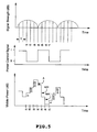
- FIG. 5 illustrates an application of the method of FIG. 4 , applied to a mobile unit 22 for a signal strength as illustrated in FIG. 2 .
- the following initial values were set to the following unitized values for an exemplary embodiment:
- the resultant power level pattern is different from that illustrated in FIG. 2 .
- the increment value is listed to the right of the step.
- a change of direction from DN to UP occurs at time t1, where the initial UP step size is given as ⁇ .
- the next step UP occurs at time t2 and has a step size of ⁇ + ⁇ , incremented from the previous step.
- the next step UP occurs at time t3 and has a step size of ⁇ +2 ⁇ , incremented again.
- the step size increases.
- a change of direction from UP to DN is illustrated at time t4, where the first DN step has a step size given as (- ⁇ ).
- the next DN step is at time t5 having a step size (-MAX).
- This DN step is followed by another DN step, wherein successive steps would have sizes, MAX- ⁇ , and MAX-2 ⁇ , respectively, such as occurs at times t6.
- successive DN steps would result in decreasing step sizes.
- time t7 there is a direction change from DN to UP.
- the step size returns to a minimum, ⁇ .
- Successive UP steps then increment by ⁇ .
- the pattern illustrated is intended to more accurately and quickly track the fading experienced at the mobile unit 22. Note that while not illustrated, the incremental step size adjustments do not continue to increase/decrease without limit. For UP adjustments, the step size reaches a maximum value MAX and does not increase further for successive UP steps.
- step size reaches a minimum value (- ⁇ ) and remains there on further successive DN steps.
- the process reaches a maximum or a minimum step size, the only change in step size occurs for changes in direction. Note that alternate embodiments may vary the step size once a limit is reached.
- Alternate embodiments may implement any number of values for the increment, minimum, and maximum variables. Additionally, these values may be dynamic values, adjusted based on performance of the mobile unit 22. Alternate embodiments may treat step adjustment in a similar manner for both directions, wherein one scheme is used rather than the diverse approach of the exemplary embodiment.
- a wireless system may include mobile units 22 implementing a variety of power control adjustment methods.
- a mobile unit may provide feedback information to a base station, allowing the base station to adjust the period T or in some other way assist the mobile in effectively tracking the fading experienced in the field.
- a base station may use this type of information from multiple mobile units within a system.
- DSP digital signal processor
- ASIC application specific integrated circuit
- FPGA field programmable gate array
- the processor may advantageously be a microprocessor, but in the alternative, the processor may be any conventional processor, controller, microcontroller, or state machine.
- the software modules could reside in RAM memory, flash memory, ROM memory, EPROM memory, EEPROM memory, registers, hard disk, a removable disk, a CD-ROM, or any other form of storage medium known in the art.
- the processor may reside in an ASIC (not shown).
- the ASIC may reside in a telephone (not shown).
- the processor may reside in a telephone.
- the processor may be implemented as a combination of a DSP and a microprocessor, or as two microprocessors in conjunction with a DSP core, etc.
Landscapes
- Engineering & Computer Science (AREA)
- Computer Networks & Wireless Communication (AREA)
- Signal Processing (AREA)
- Mobile Radio Communication Systems (AREA)
- Transmitters (AREA)
- Selective Calling Equipment (AREA)
- Circuits Of Receivers In General (AREA)
- Remote Monitoring And Control Of Power-Distribution Networks (AREA)
- Transceivers (AREA)
- Radio Relay Systems (AREA)
Applications Claiming Priority (2)
| Application Number | Priority Date | Filing Date | Title |
|---|---|---|---|
| US09/670,292 US6801759B1 (en) | 2000-09-25 | 2000-09-25 | Method and apparatus for power control in a wireless communication system |
| EP01973461A EP1329036B1 (fr) | 2000-09-25 | 2001-09-21 | Procede et appareil permettant de commander la puissance dans un systeme de communication radio |
Related Parent Applications (2)
| Application Number | Title | Priority Date | Filing Date |
|---|---|---|---|
| EP01973461A Division EP1329036B1 (fr) | 2000-09-25 | 2001-09-21 | Procede et appareil permettant de commander la puissance dans un systeme de communication radio |
| EP01973461.5 Division | 2001-09-25 |
Publications (2)
| Publication Number | Publication Date |
|---|---|
| EP1995887A2 true EP1995887A2 (fr) | 2008-11-26 |
| EP1995887A3 EP1995887A3 (fr) | 2010-06-16 |
Family
ID=24689811
Family Applications (2)
| Application Number | Title | Priority Date | Filing Date |
|---|---|---|---|
| EP01973461A Expired - Lifetime EP1329036B1 (fr) | 2000-09-25 | 2001-09-21 | Procede et appareil permettant de commander la puissance dans un systeme de communication radio |
| EP08015026A Withdrawn EP1995887A3 (fr) | 2000-09-25 | 2001-09-21 | Procédé et appareil pour la régulation de puissance dans un système de communication sans fil |
Family Applications Before (1)
| Application Number | Title | Priority Date | Filing Date |
|---|---|---|---|
| EP01973461A Expired - Lifetime EP1329036B1 (fr) | 2000-09-25 | 2001-09-21 | Procede et appareil permettant de commander la puissance dans un systeme de communication radio |
Country Status (16)
| Country | Link |
|---|---|
| US (1) | US6801759B1 (fr) |
| EP (2) | EP1329036B1 (fr) |
| JP (1) | JP4880187B2 (fr) |
| KR (1) | KR100842184B1 (fr) |
| CN (1) | CN1275395C (fr) |
| AT (1) | ATE406707T1 (fr) |
| AU (1) | AU2001293036A1 (fr) |
| BR (1) | BR0114098A (fr) |
| CA (1) | CA2423365A1 (fr) |
| DE (1) | DE60135569D1 (fr) |
| IL (1) | IL154768A0 (fr) |
| MX (1) | MXPA03002529A (fr) |
| NO (1) | NO20031326D0 (fr) |
| RU (1) | RU2003112020A (fr) |
| TW (1) | TW530515B (fr) |
| WO (1) | WO2002027968A2 (fr) |
Families Citing this family (36)
| Publication number | Priority date | Publication date | Assignee | Title |
|---|---|---|---|---|
| US7096034B2 (en) * | 2001-10-01 | 2006-08-22 | Microsoft Corporation | System and method for reducing power consumption for wireless communications by mobile devices |
| FI20012033A7 (fi) * | 2001-10-19 | 2003-04-20 | Nokia Corp | Menetelmä tehon säätämiseksi tietoliikennejärjestelmissä |
| US20040198261A1 (en) * | 2002-06-28 | 2004-10-07 | Wei Xiong | Method of self-calibration in a wireless transmitter |
| US8190163B2 (en) | 2002-08-08 | 2012-05-29 | Qualcomm Incorporated | Methods and apparatus of enhanced coding in multi-user communication systems |
| US7363039B2 (en) | 2002-08-08 | 2008-04-22 | Qualcomm Incorporated | Method of creating and utilizing diversity in multiple carrier communication system |
| US6961595B2 (en) | 2002-08-08 | 2005-11-01 | Flarion Technologies, Inc. | Methods and apparatus for operating mobile nodes in multiple states |
| US7411895B2 (en) * | 2003-02-19 | 2008-08-12 | Qualcomm Incorporated | Controlled superposition coding in multi-user communication systems |
| US8593932B2 (en) | 2003-05-16 | 2013-11-26 | Qualcomm Incorporated | Efficient signal transmission methods and apparatus using a shared transmission resource |
| US7925291B2 (en) | 2003-08-13 | 2011-04-12 | Qualcomm Incorporated | User specific downlink power control channel Q-bit |
| KR100595652B1 (ko) * | 2004-02-12 | 2006-07-03 | 엘지전자 주식회사 | 이동 통신 단말기의 송신 전력 제어 장치 및 방법 |
| US8452316B2 (en) | 2004-06-18 | 2013-05-28 | Qualcomm Incorporated | Power control for a wireless communication system utilizing orthogonal multiplexing |
| US7594151B2 (en) * | 2004-06-18 | 2009-09-22 | Qualcomm, Incorporated | Reverse link power control in an orthogonal system |
| US7197692B2 (en) | 2004-06-18 | 2007-03-27 | Qualcomm Incorporated | Robust erasure detection and erasure-rate-based closed loop power control |
| US7702351B2 (en) * | 2005-02-17 | 2010-04-20 | Qualcomm Incorporated | System and method for global power control |
| US8942639B2 (en) | 2005-03-15 | 2015-01-27 | Qualcomm Incorporated | Interference control in a wireless communication system |
| US8848574B2 (en) | 2005-03-15 | 2014-09-30 | Qualcomm Incorporated | Interference control in a wireless communication system |
| MX2007013814A (es) * | 2005-05-04 | 2008-04-17 | Nokia Corp | Tamanos de pasos de control de potencia variable para acceso de paquetes con enlace ascendente a alta velocidad (hsupa). |
| US7965789B2 (en) | 2005-08-22 | 2011-06-21 | Qualcomm Incorporated | Reverse link power control for an OFDMA system |
| KR101097021B1 (ko) | 2005-10-27 | 2011-12-20 | 콸콤 인코포레이티드 | 무선 통신 시스템에서 역방향 링크 로딩을 추정하기 위한 방법 및 장치 |
| US7778658B2 (en) | 2006-01-04 | 2010-08-17 | Lg Electronics Inc. | Fast power control step-size adaptation |
| US20070211669A1 (en) * | 2006-03-07 | 2007-09-13 | Bhupesh Manoharlal Umatt | Method and apparatus for searching radio technologies |
| US8412135B2 (en) * | 2006-07-25 | 2013-04-02 | Samsung Electronics Co., Ltd. | Apparatus and method for controlling power of transmitter in a mesh network |
| US8442572B2 (en) | 2006-09-08 | 2013-05-14 | Qualcomm Incorporated | Method and apparatus for adjustments for delta-based power control in wireless communication systems |
| US8670777B2 (en) | 2006-09-08 | 2014-03-11 | Qualcomm Incorporated | Method and apparatus for fast other sector interference (OSI) adjustment |
| US7974596B2 (en) * | 2006-09-22 | 2011-07-05 | Silicon Laboratories Inc. | Power control scheme for a power amplifier |
| JP2010516208A (ja) | 2007-01-11 | 2010-05-13 | クゥアルコム・インコーポレイテッド | 無線通信システムにおいてdtxおよびdrxを使用すること |
| US7881682B2 (en) * | 2007-01-29 | 2011-02-01 | Hewlett-Packard Development Company, L.P. | System and method for configuring a wireless module power limit |
| JP5392249B2 (ja) * | 2008-03-26 | 2014-01-22 | 日本電気株式会社 | 無線局装置、無線リソースの制御方法、無線局制御プログラム、及び無線通信システム |
| FR2960111B1 (fr) * | 2010-05-12 | 2013-04-26 | Thales Sa | Procede et dispositif de demodulation d'un signe de type dvb-s2 soumis a des perturbations |
| US8471629B2 (en) | 2011-06-30 | 2013-06-25 | Silicon Laboratories Inc | Providing automatic power control for a power amplifier |
| US8532691B2 (en) * | 2011-08-03 | 2013-09-10 | Intel Mobile Communications GmbH | Method and device for controlling a transmit power in a radio communications system |
| US9009517B2 (en) * | 2011-11-16 | 2015-04-14 | Infineon Technologies Ag | Embedded voltage regulator trace |
| KR101728732B1 (ko) * | 2012-06-15 | 2017-04-20 | 엘지전자 주식회사 | 무선 통신 시스템에서 다중 입출력 신호를 증폭하는 방법 및 장치 |
| US9332509B2 (en) | 2013-02-10 | 2016-05-03 | Qualcomm Incorporated | Transmit power control systems, devices, and methods |
| US20140369312A1 (en) * | 2013-06-14 | 2014-12-18 | Qualcomm Incorporated | Adaptive transmit power control (tpc) step size in a high speed data network |
| JP6659245B2 (ja) * | 2015-06-12 | 2020-03-04 | 株式会社東芝 | 送信装置 |
Family Cites Families (15)
| Publication number | Priority date | Publication date | Assignee | Title |
|---|---|---|---|---|
| GB414352A (en) * | 1932-10-31 | 1934-07-31 | Vierling Oskar | Electrical musical instrument |
| US5490167A (en) * | 1989-08-09 | 1996-02-06 | Touhoku-Denryoku Kabushiki Kaisha | Duplex voice communication radio transmitter-receiver |
| JP2980156B2 (ja) * | 1994-05-12 | 1999-11-22 | エヌ・ティ・ティ移動通信網株式会社 | 送信電力制御方法および該制御方法を用いたスペクトル拡散通信装置 |
| FI100072B (fi) * | 1996-01-19 | 1997-09-15 | Nokia Mobile Phones Ltd | Menetelmä lähetystehon säätämiseksi sekä radiojärjestelmä |
| JPH103790A (ja) * | 1996-06-18 | 1998-01-06 | Mitsubishi Electric Corp | 半導体記憶装置 |
| US5982760A (en) * | 1997-06-20 | 1999-11-09 | Qualcomm Inc. | Method and apparatus for power adaptation control in closed-loop communications |
| JP3393365B2 (ja) * | 1997-10-08 | 2003-04-07 | 沖電気工業株式会社 | 送信電力制御方法 |
| US6389296B1 (en) * | 1997-10-08 | 2002-05-14 | Oki Electric Industry Co., Ltd. | Transmission power control method |
| JP3913879B2 (ja) * | 1998-02-03 | 2007-05-09 | 富士通株式会社 | 移動速度に基づく通信制御装置および方法 |
| KR100266412B1 (ko) * | 1998-06-09 | 2000-09-15 | 윤덕용 | 직접 시퀀스 부호분할 다중 접속 시스템에서의 적응형 스텝 크기 전력제어 방법 |
| FI113426B (fi) * | 1998-07-16 | 2004-04-15 | Nokia Corp | Menetelmä lähetystehon säätämiseksi WCDMA-järjestelmässä |
| KR100285310B1 (ko) * | 1998-07-29 | 2001-04-02 | 윤종용 | Cdma통신시스템의삭제지시비트를이용한순방향전력제어파라미터제어방법 |
| US6178313B1 (en) * | 1998-12-31 | 2001-01-23 | Nokia Mobile Phones Limited | Control of gain and power consumption in a power amplifier |
| US6351650B1 (en) * | 1999-01-28 | 2002-02-26 | Qualcomm Incorporated | System and method for forward link power balancing in a wireless communication system |
| US6334047B1 (en) * | 1999-04-09 | 2001-12-25 | Telefonaktiebolaget Lm Ericsson (Publ) | Adaptive power control in a mobile radio communications system |
-
2000
- 2000-09-25 US US09/670,292 patent/US6801759B1/en not_active Expired - Fee Related
-
2001
- 2001-09-21 AT AT01973461T patent/ATE406707T1/de not_active IP Right Cessation
- 2001-09-21 RU RU2003112020/09A patent/RU2003112020A/ru not_active Application Discontinuation
- 2001-09-21 MX MXPA03002529A patent/MXPA03002529A/es unknown
- 2001-09-21 DE DE60135569T patent/DE60135569D1/de not_active Expired - Lifetime
- 2001-09-21 EP EP01973461A patent/EP1329036B1/fr not_active Expired - Lifetime
- 2001-09-21 KR KR1020037004235A patent/KR100842184B1/ko not_active Expired - Lifetime
- 2001-09-21 EP EP08015026A patent/EP1995887A3/fr not_active Withdrawn
- 2001-09-21 IL IL15476801A patent/IL154768A0/xx unknown
- 2001-09-21 WO PCT/US2001/029876 patent/WO2002027968A2/fr not_active Ceased
- 2001-09-21 CN CNB018195202A patent/CN1275395C/zh not_active Expired - Lifetime
- 2001-09-21 BR BR0114098-1A patent/BR0114098A/pt not_active IP Right Cessation
- 2001-09-21 JP JP2002531639A patent/JP4880187B2/ja not_active Expired - Fee Related
- 2001-09-21 CA CA002423365A patent/CA2423365A1/fr not_active Abandoned
- 2001-09-21 AU AU2001293036A patent/AU2001293036A1/en not_active Abandoned
- 2001-09-25 TW TW090123589A patent/TW530515B/zh not_active IP Right Cessation
-
2003
- 2003-03-24 NO NO20031326A patent/NO20031326D0/no not_active Application Discontinuation
Also Published As
| Publication number | Publication date |
|---|---|
| CA2423365A1 (fr) | 2002-04-04 |
| WO2002027968A2 (fr) | 2002-04-04 |
| TW530515B (en) | 2003-05-01 |
| NO20031326L (no) | 2003-03-24 |
| RU2003112020A (ru) | 2004-08-27 |
| JP2004510390A (ja) | 2004-04-02 |
| CN1494772A (zh) | 2004-05-05 |
| MXPA03002529A (es) | 2003-10-15 |
| DE60135569D1 (de) | 2008-10-09 |
| ATE406707T1 (de) | 2008-09-15 |
| EP1329036B1 (fr) | 2008-08-27 |
| IL154768A0 (en) | 2003-10-31 |
| NO20031326D0 (no) | 2003-03-24 |
| BR0114098A (pt) | 2004-01-27 |
| EP1329036A2 (fr) | 2003-07-23 |
| HK1064529A1 (en) | 2005-01-28 |
| JP4880187B2 (ja) | 2012-02-22 |
| KR20030032053A (ko) | 2003-04-23 |
| WO2002027968A3 (fr) | 2002-08-22 |
| EP1995887A3 (fr) | 2010-06-16 |
| KR100842184B1 (ko) | 2008-06-30 |
| US6801759B1 (en) | 2004-10-05 |
| AU2001293036A1 (en) | 2002-04-08 |
| CN1275395C (zh) | 2006-09-13 |
Similar Documents
| Publication | Publication Date | Title |
|---|---|---|
| US6801759B1 (en) | Method and apparatus for power control in a wireless communication system | |
| US7218945B2 (en) | Transmission power controlling method and base station apparatus | |
| EP1101293B1 (fr) | Commande de puissance dans une boucle fermee d'un systeme de radiocommunication | |
| MXPA04002906A (es) | Metodo y aparato para control de potencia de circuito externo de enlace de regreso multicanal. | |
| JP3926965B2 (ja) | 電力制御アルゴリズムを用いて移動無線通信システムの性能を改善するための方法 | |
| JP2003516062A (ja) | 無線通信装置の適合性試験をする方法 | |
| KR20010050146A (ko) | 전력 제어 알고리즘을 이용한 이동 무선 통신 시스템의성능 개선 방법 | |
| CN1183695C (zh) | 无线电通信系统中的闭环功率控制 | |
| EP1642400A1 (fr) | Systeme de radiocommunications | |
| KR20020026442A (ko) | 라디오 통신 시스템 | |
| US20010036813A1 (en) | Radio communication system | |
| US20070087770A1 (en) | Methods and apparatuses for transmission power control in a wireless communication system | |
| US6418321B1 (en) | Transmission power controller | |
| JP4138668B2 (ja) | 送信電力制御コマンドを通じて速度情報を行なうシステム及び方法 | |
| HK1064529B (en) | Method and apparatus for power control in a wireless communication system | |
| US20060217143A1 (en) | Radio communication system | |
| JPH0758690A (ja) | 送信電力制御方式 | |
| KR20000061521A (ko) | 이동통신시스템에서의 역방향전력제어방법 | |
| KR20060059510A (ko) | 무선 통신 시스템의 외부 루프 전력 제어방법 | |
| HK1066935A1 (en) | Method and apparatus for link quality feedback in a wireless communication system |
Legal Events
| Date | Code | Title | Description |
|---|---|---|---|
| PUAI | Public reference made under article 153(3) epc to a published international application that has entered the european phase |
Free format text: ORIGINAL CODE: 0009012 |
|
| AC | Divisional application: reference to earlier application |
Ref document number: 1329036 Country of ref document: EP Kind code of ref document: P |
|
| AK | Designated contracting states |
Kind code of ref document: A2 Designated state(s): AT BE CH CY DE DK ES FI FR GB GR IE IT LI LU MC NL PT SE TR |
|
| RIN1 | Information on inventor provided before grant (corrected) |
Inventor name: SAIFUDDIN, AHMED |
|
| PUAL | Search report despatched |
Free format text: ORIGINAL CODE: 0009013 |
|
| AK | Designated contracting states |
Kind code of ref document: A3 Designated state(s): AT BE CH CY DE DK ES FI FR GB GR IE IT LI LU MC NL PT SE TR |
|
| RIC1 | Information provided on ipc code assigned before grant |
Ipc: H04W 52/22 20090101AFI20100512BHEP Ipc: H04W 52/36 20090101ALI20100512BHEP |
|
| 17P | Request for examination filed |
Effective date: 20101216 |
|
| AKX | Designation fees paid |
Designated state(s): AT BE CH CY DE DK ES FI FR GB GR IE IT LI LU MC NL PT SE TR |
|
| GRAP | Despatch of communication of intention to grant a patent |
Free format text: ORIGINAL CODE: EPIDOSNIGR1 |
|
| RIC1 | Information provided on ipc code assigned before grant |
Ipc: H04W 52/22 20090101AFI20110314BHEP Ipc: H04W 52/36 20090101ALI20110314BHEP |
|
| STAA | Information on the status of an ep patent application or granted ep patent |
Free format text: STATUS: THE APPLICATION IS DEEMED TO BE WITHDRAWN |
|
| 18D | Application deemed to be withdrawn |
Effective date: 20110910 |