EP1995947A2 - Procédé et appareil de conversion de signal couleur et procédé et appareil pour générer des paramètres de cartographie - Google Patents
Procédé et appareil de conversion de signal couleur et procédé et appareil pour générer des paramètres de cartographie Download PDFInfo
- Publication number
- EP1995947A2 EP1995947A2 EP08008305A EP08008305A EP1995947A2 EP 1995947 A2 EP1995947 A2 EP 1995947A2 EP 08008305 A EP08008305 A EP 08008305A EP 08008305 A EP08008305 A EP 08008305A EP 1995947 A2 EP1995947 A2 EP 1995947A2
- Authority
- EP
- European Patent Office
- Prior art keywords
- gamut
- mapping
- color
- color signal
- input
- Prior art date
- Legal status (The legal status is an assumption and is not a legal conclusion. Google has not performed a legal analysis and makes no representation as to the accuracy of the status listed.)
- Withdrawn
Links
Images





Classifications
-
- H—ELECTRICITY
- H04—ELECTRIC COMMUNICATION TECHNIQUE
- H04N—PICTORIAL COMMUNICATION, e.g. TELEVISION
- H04N1/00—Scanning, transmission or reproduction of documents or the like, e.g. facsimile transmission; Details thereof
- H04N1/46—Colour picture communication systems
- H04N1/56—Processing of colour picture signals
- H04N1/60—Colour correction or control
- H04N1/6058—Reduction of colour to a range of reproducible colours, e.g. to ink- reproducible colour gamut
Definitions
- the present invention relates to a color signal conversion method and apparatus for converting a color signal of an input gamut to a color signal of an output gamut, and to a method and apparatus for generating mapping parameters.
- Gamut mapping is a technique that associates a certain gamut with another gamut in a uniform colorimetric system, and is known as a conventional technique for color reproduction aimed at achieving perceptual matching between images when utilizing paper types, display media, and the like that have different gamuts.
- a technique by which complex map conversion from a single dimension to three dimensions is carried out over plural stages for example, see Japanese Patent Laid-Open No. 2001-94799
- a technique that realizes a gamut map by expressing gradation representing color change as a curve for example, see Japanese Patent Laid-Open No. 2002-33929 .
- cyan (C) and magenta (M) components will contaminate and muddy the Y component if hue deviation occurs with the gamut map.
- Such muddied color is prominent in the high brightness range of the Y component, and is perceptually apparent as a change in the hue.
- a technique that achieves perceptually favorable color reproduction by correcting hue deviation in the input and output gamuts respectively has accordingly been proposed (for example, see Japanese Patent Laid-Open No. 2002-152536 ).
- a user is required to manually adjust a large number of color conversion parameters when mapping a gamut from a monitor to a color printer.
- the optimal combination of parameters also depends on, among other things, the monitor and printer models, and thus it takes an inordinate amount of time for the user to determine the optimal control parameters for the gamut map.
- mapping parameters are provided in some mapping conversion processes in order to make it easier for the user to control the mapping process, it is nevertheless difficult to understand the effects of the mapping parameters and the influence they have on the overall process.
- the present invention in one aspect provides a color signal conversion method as specified in claims 1 to 9.
- the present invention in another aspect provides a color signal conversion apparatus as specified in claims 10 and 11.
- the present invention in still another aspect provides a method for generating mapping parameters as specified in claims 12 and 13.
- the present invention in yet another aspect provides an apparatus for generating mapping parameters as specified in claims 14 and 15.
- mapping parameters can be automatically adjusted when converting a color signal of the input gamut to a color signal of the output gamut. Furthermore, colors can be favorably reproduced by automatically correcting hue deviation in the input and output gamuts respectively.
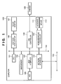
- FIG. 1 is a block diagram illustrating an example of a configuration of a system according to an embodiment of the present invention.
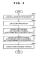
- FIG. 2 is a flowchart illustrating color conversion processing performed by a printer driver according to an embodiment of the present invention.
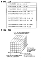
- FIG. 3A is a diagram illustrating grid points expressed by LUT grid structure data according to an embodiment of the present invention.
- FIG. 3B is a diagram illustrating an example of the configuration of a color correction LUT according to an embodiment of the present invention.
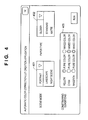
- FIG. 4 is a diagram illustrating an example of a GUI displayed when automatically creating a color correction LUT according to an embodiment of the present invention.
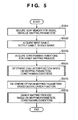
- FIG. 5 is a flowchart illustrating a process for automatically creating a color correction LUT according to an embodiment of the present invention.
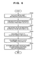
- FIG. 6 is a flowchart illustrating a process for determining an evaluation function (S504) according to an embodiment of the present invention.
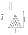
- FIG. 7 is a diagram illustrating an example of a target gamut and the result of an initial gamut mapping process, with respect to the R hue.
- FIG. 8 is a flowchart illustrating a gamut mapping process (S506) according to an embodiment of the present invention.
- FIG. 9 is a diagram illustrating examples of a color monitor gamut, a first intermediate gamut, and a printer gamut, with respect to the G hue.
- FIG. 10 is a diagram illustrating examples of a first intermediate gamut, a second intermediate gamut, and a printer gamut, with respect to the G hue.
- FIG. 11 is a diagram illustrating examples of a second intermediate gamut, a mapping result gamut, and a printer gamut, with respect to the G hue.
- FIG. 12 is a flowchart illustrating a direct mapping process (S804) according to an embodiment of the present invention.
- FIG. 13 is a flowchart illustrating a brightness/hue mapping process (S805) according to an embodiment of the present invention.
- FIG. 14 is a diagram illustrating an example of a hue input/output function h80( ⁇ ) according to an embodiment of the present invention.
- FIG. 15A is a diagram illustrating an example of a map function 10( ⁇ ) according to an embodiment of the present invention.
- FIG. 15B is a diagram illustrating an example of a map function 150( ⁇ ) according to an embodiment of the present invention.
- FIG. 15C is a diagram illustrating an example of a map function 1100( ⁇ ) according to an embodiment of the present invention.
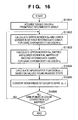
- FIG. 16 is a flowchart illustrating a brightness adjustment mapping process (S806) according to an embodiment of the present invention.
- FIG. 17 is a diagram illustrating a brightness adjustment mapping process according to an embodiment of the present invention.
- FIG. 18A is a diagram illustrating an example of an input/output function p( ⁇ ) used for brightness adjustment mapping according to an embodiment of the present invention.
- FIG. 18B is a diagram illustrating another example of an input/output function p( ⁇ ) used for brightness adjustment mapping according to an embodiment of the present invention.
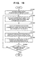
- FIG. 19 is a flowchart illustrating a saturation adjustment mapping process (S807) according to an embodiment of the present invention.
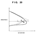
- FIG. 20 is a diagram illustrating a saturation adjustment mapping process according to an embodiment of the present invention.
- FIG. 21A is a diagram illustrating an example of an input/output function q( ⁇ ) used for saturation adjustment mapping according to an embodiment of the present invention.
- FIG. 21B is a diagram illustrating an example of an input/output function q( ⁇ ) used for saturation adjustment mapping according to an embodiment of the present invention.
- FIG. 1 is a block diagram illustrating an example of a configuration of a system according to an embodiment of the present invention.
- the system according to the present embodiment is, as illustrated in FIG. 1 , configured of a computer 100, which functions as an image processing apparatus in the present embodiment, and a printer 109, which serves as an example of an image output apparatus.
- the computer 100 shall be described first.
- a generic PC personal computer
- WS workstation
- the like can be employed as the computer 100.
- a CPU 101 carries out overall control of the computer 100 using programs, data, and so on stored in a main memory 102, and executes the processes, described later, that the computer 100 carries out.
- the main memory 102 can provide various areas as appropriate. These areas include an area for temporarily storing programs, data, and so on loaded from an HDD (hard disk drive device) 105, a working area used when the CPU 101 executes various processes, and so on.
- a SCSI interface 103 functions as an interface for connecting the HDD 105 to a bus 114.
- a network interface 104 functions as an interface for connecting the computer 100 to a network line 113, examples of which are a LAN, the Internet, and so on.
- the network interface 104 therefore depends on the network line 113.
- the HDD 105 stores an OS (operating system), programs, data, and so on for causing the CPU 101 to execute the processes, described later, carried out by the computer 100, driver software for the printer 109, and so on. These items are loaded into the main memory 102 as appropriate under the control of the CPU 101, to be processed by the CPU 101.
- OS operating system
- programs, data, and so on for causing the CPU 101 to execute the processes, described later, carried out by the computer 100, driver software for the printer 109, and so on.
- a graphics accelerator 106 performs processing for transferring images processed by the CPU 101 to a color monitor 107.
- the color monitor 107 is configured using a CRT, LCD, or the like, and is capable of displaying the results of processes performed by the CPU 101 as images, characters, or the like.
- a USB controller 108 functions as an interface for connecting the printer 109 to the bus 114.
- a keyboard/mouse controller 110 functions as an interface for connecting a keyboard 111, a mouse 112, or the like to the bus 114. Instructions input by an operator of the computer 100 using the keyboard 111 and the mouse 112 are communicated to the CPU 101 via the keyboard/mouse controller 110.
- Printers generally have various types of recording systems, but in the present embodiment, the recording systems, functionality, and so on of the printer 109 are not intended to be limited in any particular manner.
- the present system is capable of displaying an image in the color monitor 107 as well as printing an image using the printer 109. Regardless of which of these is carried out, it is necessary for the main memory 102 to acquire the image, and various methods for this image acquisition can be considered. Assume, for example, that the operator of the computer 100 uses the keyboard 111 and the mouse 112 to specify a desired image from among images stored in the HDD 105. In such a case, the CPU 101 reads out the specified image from the HDD 105 in response to the operator's specification. The CPU 101 then transfers the read-out image to the main memory 102 via the SCSI interface 103 and the bus 114.
- Another method assumes that the operator of the computer 100 uses the keyboard 111 and the mouse 112 to specify a desired image from among images stored in a device connected to the network line 113.
- the CPU 101 acquires the specified image from the device and stores it in the main memory 102, via the network interface 104 and the bus 114.
- the CPU 101 then transfers the acquired image from the main memory 102 to the graphics accelerator 106.
- the graphics accelerator 106 executes predetermined processing on the transferred image, and then transfers the processed image to the color monitor 107. The image is therefore displayed on the display surface of the color monitor 107.
- the CPU 101 passes the image from the HDD 105 to the driver software of the printer 109, which is already loaded in the main memory 102.
- the CPU 101 then runs the driver software.
- the driver software first performs color conversion processing on the image.
- the color conversion processing shall be described later.
- the driver software then converts the image on which the color conversion processing has been performed into a CMYK image, and transfers the converted CMYK image to the printer 109 via the USB controller 108.
- the printer 109 records the CMYK image onto a recording medium such as paper.
- FIG. 2 is a flowchart that illustrates this processing.
- image data stored in the main memory 102 is acquired (S201).
- this image data is assumed to be digital data of an image composed of pixels having color information expressed by the RGB color model (in other words, an RGB image). Note that there are, as mentioned above, various methods for acquiring the image, and thus no particular limitations shall be placed thereon.
- a color correction LUT (Look-Up Table), which has been created by an automatic color correction LUT creation application (mentioned later) and stored in the HDD 105, is loaded into the main memory 102 (S202).
- a "color correction LUT” is a table that associates grid point coordinate values of colors in the RGB color space with grid point coordinate values of colors in the L*a*b* color space that correspond to the RGB colors, and is configured, for example, as illustrated in FIG. 3B.
- FIG. 3B is a diagram illustrating an example of the configuration of the color correction LUT.
- the color correction LUT is comprised of an LUT grid structure data portion and an LUT grid point data portion.
- the values that R, G, and B can take on are denoted in the LUT grid structure data.
- R, G, and B in FIG. 3B can all take on discrete values within a range from 0 to 255, in increments, or steps, of 32. In other words, the values that R, G, and B can take on are 0, 32, 64, and so on up to 224, finally stopping at 255.
- FIG. 3A is a diagram illustrating grid points expressed by the LUT grid structure data. Because R, G, and B take on a value of 0, 32, 64... 224, or 255, as described above, the R axis, G axis, and B axis are each divided into 8 equal divisions. The coordinate values of each grid point are expressed as "Grid(R/32, G/32, B/32)".
- LUT grid point data The coordinate values of grid points in the L*a*b* color space that corresponds to the grid points in the RGB color space shown in FIG. 3A are written in the LUT grid point data.
- LUTs which indicate a corresponding relationship between colors in the RGB color space and colors in the L*a*b* color space, are publicly-known and thus further descriptions thereof shall be omitted.
- the example provided in the present embodiment uses the L*a*b* color space as an intermediate color reproduction color space, which is not dependent on the input color space (that is, the RGB color space) or the output color space (that is, the CMYK color space).
- the intermediate color reproduction color space is not intended to be limited to L*a*b*; any color space may be used as long as it is a uniform color space that is not dependent upon the input and output color spaces.
- the color correction LUT acquired in step S202 is used to convert the image acquired in step S201 (here, an image in which R, G, and B are each expressed with 24 bits) into L*a*b* fixed point data (S203).
- the converted data is stored in the main memory 102. Furthermore, tetrahedral interpolation is used in this conversion.
- the L*a*b* fixed point data obtained through the conversion performed in step S203 is converted into 32-bit CMYK image data (an image in which C, M, Y, and K are each expressed with 32 bits) using a predetermined color conversion LUT (S204).
- This color conversion LUT is created in advance and stored in the HDD 105.
- the 32-bit CMYK image data obtained through the conversion performed in step S204 is stored in the main memory 102.
- the 32-bit CMYK image data obtained through the conversion performed in step S204 is then output to the printer 109 via the USB controller 108 (step S205).
- the automatic color correction LUT creation application which creates the color correction LUT that is loaded in the abovementioned step S202.
- the automatic color correction LUT creation application is stored in the HDD 105, and is loaded into the main memory 102 as appropriate under the control of the CPU 101.
- FIG. 4 is a diagram illustrating an example of a GUI displayed for automatically creating a color correction LUT.
- a scene mode menu 401, paper type menu 402, and constraining conditions menu 403 used when outputting the image data can be specified.
- the user can select a mode suited to the image data, from among several preset options, such as "portrait”, “landscape”, “night scene”, and so on.
- a gamut set to correspond to the mode in question is then set as the target gamut based on the selection made using the scene mode menu 401.
- the target gamut is set in response to the user's instructions.
- the target gamut is defined by setting the target colors according to a scene, with respect to a plurality of colors in the input gamut, as a color signal in the intermediate color reproduction color space.
- the user can select a paper type on which to output the image data, from among several preset options, such as "standard”, “matte”, “glossy”, and so on.
- a gamut set to correspond to the output paper type in question is then set as the gamut in the printer 109 (that is, as the output gamut) based on the selection made using the paper type menu 402.
- a gamut is set in the printer 109 in response to the user's instructions.
- constraining conditions menu 403 constraining conditions for outputting colors of a specific hue in the output gamut as pure colors are set. That is, with the constraining condition setting process of the present embodiment, the user can select whether or not to hold pure colors in the printer 109 with regard to hues such as yellow, magenta, cyan, and so on. For example, the following control is carried out when "pure color" has been selected for yellow.
- the colors spanning from white to yellow obtained by continuously changing the intensity of yellow in the input gamut are reproduced by colors obtained by continuously changing the intensity of yellow in the output gamut, or in other words, are reproduced using only the pure yellow of the printer 109.
- the scene mode can be set based on information recorded in the EXIF data region.
- the input gamut in the present embodiment is dependent upon the RGB color space of the image data, and thus corresponds to a gamut used by a typical color monitor, such as an sRGB gamut, an Adobe RGB gamut, and so on.
- a typical color monitor such as an sRGB gamut, an Adobe RGB gamut, and so on.
- the colors of each grid point in the L*a*b* color space that correspond to each grid point in the RGB color space are taken as the gamut of the color monitor. Accordingly, once the settings carried out using the GUI illustrated in FIG. 4 have ended, the colors of each grid point in the L*a*b* color space that correspond to each grid point in the RGB color space are registered as the gamut of the color monitor, the gamut of the printer 109, and the target gamut.
- FIG. 5 is a flowchart that illustrates this process.
- a heap memory is secured for tasks in the main memory 102, and various initialization processes, such as the initialization of mapping parameters, are carried out (S501).
- the color monitor gamut, printer gamut, and target gamut are then acquired based on the details specified using the GUI illustrated in FIG. 4 and are loaded into the main memory 102 (S502).
- the constraining conditions for the gamut mapping process are acquired through the GUI illustrated in FIG. 4 (S503). In the present embodiment, it is assumed that only yellow has been selected to be held as a pure color.
- an evaluation function for determining the mapping parameters is determined (S504).
- a weighting coefficient for calculating evaluation values is determined based on the constraining conditions. This shall be described in detail later.
- mapping parameters are determined based on the evaluation function (S505).
- the mapping parameters are determined in such a manner that the evaluation values based on the evaluation function are minimum values.
- a well-known optimization method can be used as this determination method. For example, a binary tree search method, the quasi-Newton method, and so on can be used.
- the gamut mapping process is carried out based on the mapping parameters.
- the color signal of the color monitor gamut is mapped to the gamut of the printer 109, in the L*a*b* color space (S506). Details regarding the gamut mapping process shall be given later.
- the color correction LUT loaded in step S202 is therefore completed through this process.
- FIG. 6 is a flowchart illustrating the details of the process for determining the evaluation function performed in step S504.
- the colors of each grid point in the L*a*b* color space that correspond to each grid point in the RGB color space are obtained through the abovementioned step S502 as the gamut of the color monitor.
- the colors of the grid points in the L*a*b* color space obtained through a gamut mapping process similar to that indicated in step S506 are then calculated based on the mapping parameters initialized in step S501, for each grid point (S600).
- the result of mapping the grid points in the L*a*b* color space, calculated as mentioned here and obtained through the gamut mapping process based on the initialized mapping parameters shall be called the "initial gamut mapping process result".
- between corresponding grid points is then found based on the obtained initial gamut mapping process result and the target color of the grid points loaded into the main memory 102 in the aforementioned step S502 (S601).
- thereof is found (S602).
- the target value is not identical to the number of grid points or the grid point interval of the L*a*b* color space, target colors corresponding to the grid points in the L*a*b* color space are calculated using interpolation.
- a single hue is selected from the six RGBCMY hues, and a color difference ⁇ E between the initial gamut mapping process result for plural grid points located on the screen for the selected hue and the corresponding target gamut is found (S603).
- the relationship between the target color data and the initial gamut mapping process result with regards to the red (R) hue is illustrated in FIG. 7 .
- the solid line represents the initial gamut mapping process result
- the dotted line represents the target color data.
- the color difference between corresponding grid points in FIG. 7 is found as ⁇ E.
- the average value of the instances of ⁇ E found for each of the RGBCMY hues, or ⁇ Ei, is found next (S604).
- the i in ⁇ Ei is a subscript expressing which of RGBCMY the hue is.
- an evaluation value E that verifies the difference between the gamut mapping result using the mapping parameter and the target color, or in other words, an evaluation function, is found based on the following formula (S605).
- ⁇ i represents the weighting coefficient set based on the constraining conditions acquired in step S503. For example, if yellow has been selected to be a pure color as part of the constraining conditions, the color difference average ⁇ Ei between the initial gamut mapping process result and the target gamut with respect to the yellow (Y) hue naturally grows larger; therefore, the weighting coefficient ⁇ i is made relatively smaller so as to achieve an appropriate evaluation function.
- step S506 The gamut mapping process indicated in the aforementioned step S506 shall be described hereinafter, with reference to the flowchart illustrated in FIG. 8 .
- the gamut of the color monitor, the gamut of the printer 109, and the target gamut loaded into the main memory 102 in the aforementioned step S502 are acquired (S801).
- the colors of each grid point in the L*a*b* color space that correspond to each grid point in the RGB color space are registered as the gamut of the color monitor, the gamut of the printer 109, and the target gamut, as mentioned above.
- a single color c is selected from the grid points in the RGB color space (S802). After this, it is determined whether or not the color c is a color subject to the constraining conditions, or in other words, whether or not the color can be expressed solely by a color set so as to be held as a pure color by the constraining conditions (S803). If the color c is subject to the constraining conditions, a process for directly mapping the gamut of the color monitor to the gamut of the printer 109 is carried out (S804). Details regarding this mapping process shall be given later.
- FIG. 9 shows a gamut 901 of the color monitor, a first intermediate gamut 902, and a gamut 903 of the printer 109, with respect to the green (G) hue.
- the color in the gamut of the color monitor is divided into a brightness component and a chromaticity component, and the brightness component is mapped non-linearly. With respect to the chromaticity component, the hue thereof is adjusted in an appropriate manner.
- the gamut 901 of the color monitor is mapped to the first intermediate gamut 902. Details regarding the brightness/hue mapping processes shall be given later.
- FIG. 10 shows a first intermediate gamut 1001, a second intermediate gamut 1002, and a gamut 1003 of the printer 109, with respect to the green (G) hue.
- the color in the first intermediate gamut 1001 is divided into a brightness component and a chromaticity component, and the brightness component is mapped non-linearly, while the chromaticity component is kept constant. Note that the brightness input/output function for implementing mapping differs depending on the chromaticity.
- the first intermediate gamut 1001 is mapped to the second intermediate gamut 1002. Details regarding the brightness adjustment mapping process shall be given later.
- FIG. 11 shows a second intermediate gamut 1101, a mapping result gamut 1102, and a gamut 1103 of the printer 109, with respect to the green (G) hue.
- the color in the second intermediate gamut 1101 is divided into a brightness component and a chromaticity component, and the saturation component in the chromaticity component is mapped non-linearly, while the brightness component is kept constant.
- the second intermediate gamut 1101 is mapped to the mapping result gamut 1102. It can be seen in FIG. 11 that the mapping result gamut 1102 is almost completely contained within the gamut 1103 of the printer 109. Details regarding the saturation adjustment mapping process shall be given later.
- step S808 it is determined whether or not the mapping process described thus far has been carried out for all grid points in the RGB color space (S808). If there are unprocessed grid points, the process returns to step S802, where a grid point that has not yet been selected is selected, and the above mapping process is carried out on the selected grid point.
- step S804 The direct mapping process indicated in the aforementioned step S804 shall be described hereinafter, with reference to the flowchart illustrated in FIG. 12 .
- Coordinate values c_i which are coordinate values in the gamut of the color monitor, and coordinate values c_t, which are coordinate values in the target gamut, are then acquired; these coordinate values correspond to the grid point information acquired in step S1201 (S1202).
- the information of the grid points in the RGB color space is not equal to the number of grid points or grid point intervals in the gamut of the color monitor or the target gamut, coordinate values corresponding to the grid point information are calculated through interpolation.
- a pure color line 1_p is acquired for the hue, which has specified to be held as a pure color due to the constraining conditions, in the gamut of the printer 109, the hue corresponding to the grid point information acquired in step S1201 (S1203).
- "Pure color line” refers to the trajectory of a color in which the intensity of the pure color in the gamut of the printer 109 is continuously changed, or in other words, a line from white to the pure color's maximum intensity. For example, if the gamut of the printer has the color distribution indicated by the color correction LUT shown in FIG. 3A , the pure color line can be calculated through interpolation based on the coordinate values of discrete grid points.
- mapping process used here may employ a publicly-known mapping method. For example, mapping that brings the color difference to a minimum may be used.
- the coordinate values c_p on the pure color line 1_p are set as the mapping destination of the coordinate values c_i corresponding to the information of the grid points in the gamut of the color monitor (S1205).
- mapping is carried out onto the pure color line for the color subject to the constraining conditions set using the GUI shown in FIG. 4 . Accordingly, hue deviation can be corrected automatically in the input and output gamuts with respect to colors for which pure colors are desirable (for example, yellow and the like), thereby avoiding muddying caused by contamination from other colors and making perceptually favorable color reproduction possible.
- step S805 The brightness/hue mapping process indicated in the aforementioned step S805 shall be described hereinafter, with reference to the flowchart illustrated in FIG. 13 .
- hue input/output functions used as references are first generated (S1301). For example, hue input/output functions h0( ⁇ ), h20( ⁇ ), h40( ⁇ ), h60( ⁇ ), h80( ⁇ ), and h100( ⁇ ) are respectively generated for six brightnesses 0, 20, 40, 60, 80, and 100.
- the hue input/output functions h( ⁇ ) are calculated based on mapping parameters h_p that respectively control each of the six hues (R, G, B, C, M, Y) in each brightness.
- the mapping parameters h_p indicate the amount by which the hue angles of each hue are corrected.
- These parameters are hue control values that take on values of integers from -20 to 20 using radian notation assuming that the counter-clockwise direction is positive, and are set in step S505.
- the mapping parameters h_p are optimized so that the evaluation values based on the evaluation function set in step S504 are minimum.
- a hue input/output function h80( ⁇ ) as indicated by the solid line in FIG. 14 is obtained. Note that in FIG. 14 , the hue angle is expressed using radian notation assuming that the counter-clockwise direction is positive, with the forward direction of the b* axis taken as the hue angle 0 rad in an a*b* chromaticity coordinate system.
- the subsequent processing is carried out for each color corresponding to the respective grid points in the RGB color space. Therefore, first, a single grid point is selected from the gamut of the color monitor, and a color p corresponding to the selected grid point is acquired (S1302). After this, the hue input/output function h0( ⁇ ) is generated for the color p using the abovementioned h0( ⁇ ), h20( ⁇ ), h40( ⁇ ), h60( ⁇ ), h80( ⁇ ), and h100( ⁇ ) (S1303).
- a hue input/output function hup( ⁇ ) corresponding to a brightness value "up” that is directly above the brightness x and a hue input/output function hlw( ⁇ ) corresponding to a brightness value "lw" that is directly below the brightness x are first identified from among the brightnesses 0, 20, 40, 60, 80, and 100.
- the hue input/output function h( ⁇ ) for the color p is then calculated through the following formula, using the hue input/output functions hup( ⁇ ) and hlw( ⁇ ).
- h ⁇ hlw ⁇ ⁇ up - x + hup ⁇ ⁇ x - lw / 20
- the hue input/output function h( ⁇ ) for the color p is calculated as follows, using the hue input/output functions h80( ⁇ ) and h60( ⁇ ).
- Hue_m mapped h Hue_m
- the brightness component of the color p is then mapped (S1305).
- the pre-mapping brightness Lin is mapped to Lmapped using a single mapping function not dependent on the chromaticity.
- mapping function 1( ⁇ ) in the above formula is defined as below, based on the mapping parameter 1_all that controls the overall brightness.
- step S1306 it is determined whether or not the series of mapping processes described above have been executed on all grid points (S1306). If there are unprocessed grid points, the process returns to step S1302, where a grid point that has not yet been selected is selected, and the above mapping process is carried out on the selected grid point.
- step S806 The brightness adjustment mapping process indicated in the aforementioned step S806 shall be described hereinafter, with reference to the flowchart showing this process, illustrated in FIG. 16 .
- FIG. 17 illustrates examples of the color q, the upper border Bu, the lower border Bl, the upper border Bu_mapped, and the lower border Bl_mapped.
- the solid line indicates the first intermediate gamut
- the dot-dash line indicates the second intermediate gamut
- the dotted line indicates the gamut of the printer 109.
- the shapes of the gamuts in FIG. 17 are identical to the examples shown in FIG. 10 .
- an input/output function p( ⁇ ), which maps the brightness adjustment, is found (S1604).
- the input/output function p( ⁇ ) is calculated as a C2-continuous cubic spline function that fulfils the following conditions:
- mapping parameters l_low and l_high which control the brightness, are optimized within the range from 0.5 to 2.0 so that the so that the evaluation values based on the abovementioned evaluation function are minimum.
- FIGS. 18A and 18B illustrate an example of the input/output function p( ⁇ ).
- the brightness in the central portion of the range is maintained.
- the change in the brightness in FIG. 18B is great, and although a characteristic in which the brightness is held can be seen in the central portion of the range, it is not held completely.
- LBl 60
- LBlm 46
- the pre-mapping brightness Lm of the color q is converted (mapped) using the input/output function p( ⁇ ) found in step S1604, and a post-mapping brightness Lm_mapped is found (S1605).
- the formula for this mapping is as follows.
- FIG. 20 illustrates examples of the color r, the border Bp, and the border Bi.
- the solid line indicates the second intermediate gamut
- the dotted line indicates the border in the gamut resulting from the gamut mapping process
- the dot-dash line indicates the gamut of the printer 109.
- the shapes of the gamuts in FIG. 20 are identical to those shown in FIG. 11 .
- an input/output function q( ⁇ ), which maps the saturation adjustment, is found (S1904).
- the input/output function q( ⁇ ) is calculated as a C2-continuous cubic spline function that fulfils the following conditions:
- mapping parameters c_low and c_high which control the saturation, are optimized within the range from 0.5 to 2.0 so that the evaluation values based on the abovementioned evaluation function are minimal.
- FIGS. 21A and 21B illustrate an example of the input/output function q( ⁇ ).
- the saturation adjustment value c_low is 0.8, and thus the saturation is being suppressed in the low/medium saturation portions.
- c_low is 1.2, and thus the saturation is being accentuated in the low/medium saturation portions.
- the pre-mapping saturation c_org of the color r is converted (mapped) using the input/output function q( ⁇ ) found in step S1804, and a post-mapping saturation c_mod is found (S1905).
- the formula for this mapping is as follows.
- the gamut 901 of the color monitor illustrated in FIG. 9 is thus mapped to the gamut 903 of the printer 109.
- the color correction LUT is completed.
- the present invention can be applied to an apparatus comprising a single device or to system constituted by a plurality of devices.
- the invention can be implemented by supplying a software program, which implements the functions of the foregoing embodiments, directly or indirectly to a system or apparatus, reading the supplied program code with a computer of the system or apparatus, and then executing the program code.
- a software program which implements the functions of the foregoing embodiments
- reading the supplied program code with a computer of the system or apparatus, and then executing the program code.
- the mode of implementation need not rely upon a program.
- the program code installed in the computer also implements the present invention.
- the claims of the present invention also cover a computer program for the purpose of implementing the functions of the present invention.
- the program may be executed in any form, such as an object code, a program executed by an interpreter, or script data supplied to an operating system.
- Example of storage media that can be used for supplying the program are a floppy disk, a hard disk, an optical disk, a magneto-optical disk, a CD-ROM, a CD-R, a CD-RW, a magnetic tape, a non-volatile type memory card, a ROM, and a DVD (DVD-ROM and a DVD-R).
- a client computer can be connected to a website on the Internet using a browser of the client computer, and the computer program of the present invention or an automatically-installable compressed file of the program can be downloaded to a recording medium such as a hard disk.
- the program of the present invention can be supplied by dividing the program code constituting the program into a plurality of files and downloading the files from different websites.
- a WWW World Wide Web
- a storage medium such as a CD-ROM
- an operating system or the like running on the computer may perform all or a part of the actual processing so that the functions of the foregoing embodiments can be implemented by this processing.
- a CPU or the like mounted on the function expansion board or function expansion unit performs all or a part of the actual processing so that the functions of the foregoing embodiments can be implemented by this processing.
Landscapes
- Engineering & Computer Science (AREA)
- Multimedia (AREA)
- Signal Processing (AREA)
- Facsimile Image Signal Circuits (AREA)
- Image Processing (AREA)
- Color Image Communication Systems (AREA)
Applications Claiming Priority (1)
| Application Number | Priority Date | Filing Date | Title |
|---|---|---|---|
| JP2007134581A JP4996338B2 (ja) | 2007-05-21 | 2007-05-21 | 色処理方法および色処理装置 |
Publications (2)
| Publication Number | Publication Date |
|---|---|
| EP1995947A2 true EP1995947A2 (fr) | 2008-11-26 |
| EP1995947A3 EP1995947A3 (fr) | 2011-09-14 |
Family
ID=39580244
Family Applications (1)
| Application Number | Title | Priority Date | Filing Date |
|---|---|---|---|
| EP08008305A Withdrawn EP1995947A3 (fr) | 2007-05-21 | 2008-04-30 | Procédé et appareil de conversion de signal couleur et procédé et appareil pour générer des paramètres de cartographie |
Country Status (4)
| Country | Link |
|---|---|
| US (1) | US7982912B2 (fr) |
| EP (1) | EP1995947A3 (fr) |
| JP (1) | JP4996338B2 (fr) |
| CN (1) | CN101312487B (fr) |
Cited By (2)
| Publication number | Priority date | Publication date | Assignee | Title |
|---|---|---|---|---|
| EP2375719A1 (fr) * | 2010-04-09 | 2011-10-12 | Thomson Licensing | Procédé de mise en correspondance de gamme de couleurs doté de la conservation de la luminosité des couleurs de cuspides |
| CN110246086A (zh) * | 2018-03-07 | 2019-09-17 | 舜宇光学(浙江)研究院有限公司 | 彩色图像增强的图像处理方法及其图像处理系统 |
Families Citing this family (21)
| Publication number | Priority date | Publication date | Assignee | Title |
|---|---|---|---|---|
| US20090220151A1 (en) * | 2008-02-29 | 2009-09-03 | Himax Technologies Limited | Device for adjusting image color difference value and adjusting method thereof |
| JP5177751B2 (ja) * | 2008-09-29 | 2013-04-10 | ルネサスエレクトロニクス株式会社 | 表示駆動回路 |
| JP5245798B2 (ja) * | 2008-12-16 | 2013-07-24 | 富士ゼロックス株式会社 | 情報処理装置及びプログラム |
| JP4715915B2 (ja) * | 2008-12-25 | 2011-07-06 | ブラザー工業株式会社 | 色変換テーブル作成装置、色変換テーブル作成方法、および色変換テーブル作成プログラム |
| JP5440195B2 (ja) * | 2010-01-15 | 2014-03-12 | コニカミノルタ株式会社 | カラープロファイルの作成方法、カラープロファイルを作成する画像処理装置、及び当該画像処理装置の制御プログラム |
| US8711453B2 (en) | 2010-05-24 | 2014-04-29 | Canon Kabushiki Kaisha | Data processing apparatus and data processing method for reducing an uneven color made up of two or more ink colors |
| CN102985906B (zh) * | 2010-07-16 | 2015-12-02 | 惠普发展公司,有限责任合伙企业 | 基于颜色配置文件调整显示设备的颜色输出 |
| JP5815386B2 (ja) | 2011-12-02 | 2015-11-17 | 富士フイルム株式会社 | 画像処理装置、画像処理方法およびプログラム |
| US9852499B2 (en) * | 2013-12-13 | 2017-12-26 | Konica Minolta Laboratory U.S.A., Inc. | Automatic selection of optimum algorithms for high dynamic range image processing based on scene classification |
| EP3393115B1 (fr) * | 2015-12-18 | 2021-08-18 | Seiko Epson Corporation | Procédé de création de table de conversion de couleurs |
| MX388842B (es) | 2016-10-05 | 2025-03-20 | Dolby Laboratories Licensing Corp | Mensajeria de informacion de volumen de color de origen |
| EP3399735A1 (fr) * | 2017-05-02 | 2018-11-07 | Thomson Licensing | Procédé et dispositif de mappage de gamme de couleurs |
| CN107343187B (zh) * | 2017-07-24 | 2021-08-24 | 深圳Tcl新技术有限公司 | 色域映射方法、显示终端及计算机可读存储介质 |
| CN110392243B (zh) | 2018-04-16 | 2021-04-09 | 华为技术有限公司 | 色域映射的方法和装置 |
| US20220132000A1 (en) * | 2019-07-10 | 2022-04-28 | Hewlett-Packard Development Company, L.P. | Color space conversion |
| KR20210045027A (ko) * | 2019-10-16 | 2021-04-26 | 주식회사 실리콘웍스 | 미세 보정이 가능한 색역 매핑 장치 |
| CN112233605B (zh) * | 2020-10-28 | 2022-08-09 | 合肥京东方光电科技有限公司 | 色域调整方法、装置、电子设备及存储介质 |
| KR102765727B1 (ko) * | 2020-11-23 | 2025-02-11 | 주식회사 엘엑스세미콘 | 색역 매핑 장치의 튜닝 방법 및 장치 |
| CN112599093B (zh) * | 2020-12-31 | 2022-10-14 | 北京奕斯伟计算技术股份有限公司 | 基于hsv色彩转换模型实现色彩映射的方法、装置和显示装置 |
| JP7823407B2 (ja) * | 2022-01-31 | 2026-03-04 | セイコーエプソン株式会社 | プロファイル作成装置、及びプロファイルの作成方法 |
| CN121168342B (zh) * | 2025-11-19 | 2026-03-20 | 华南理工大学 | 基于色彩识别的天然气水合物开采方法和系统 |
Citations (3)
| Publication number | Priority date | Publication date | Assignee | Title |
|---|---|---|---|---|
| JP2001094799A (ja) | 1999-09-17 | 2001-04-06 | Canon Inc | 画像処理方法、装置および記録媒体 |
| JP2002033929A (ja) | 2000-07-14 | 2002-01-31 | Canon Inc | 画像処理方法、装置および記録媒体 |
| JP2002152536A (ja) | 2000-11-14 | 2002-05-24 | Fuji Xerox Co Ltd | 画像処理装置及び画像処理方法 |
Family Cites Families (14)
| Publication number | Priority date | Publication date | Assignee | Title |
|---|---|---|---|---|
| DE69420874T2 (de) * | 1993-02-12 | 2000-05-04 | Eastman Kodak Co., Rochester | Verfahren zur geräteübergreifenden Farbbildkalibrierung und -verbesserung |
| US5857063A (en) * | 1997-03-27 | 1999-01-05 | Eastman Kodak Company | Multicolorant process control |
| US7116441B1 (en) * | 1998-12-21 | 2006-10-03 | Canon Kabushiki Kaisha | Signal processing apparatus image processing apparatus and their methods |
| JP4014354B2 (ja) * | 1999-07-28 | 2007-11-28 | 富士フイルム株式会社 | 色変換テーブル作成方法および装置並びにそれを用いたプルーフ作成装置 |
| US20030164968A1 (en) * | 2002-02-19 | 2003-09-04 | Canon Kabushiki Kaisha | Color processing apparatus and method |
| JP2004023738A (ja) * | 2002-06-20 | 2004-01-22 | Canon Inc | 画像処理装置及びその方法 |
| CN1543227B (zh) * | 2003-05-22 | 2010-05-12 | 中国科学院长春光学精密机械与物理研究所 | 一种平板显示屏色度空间变换修正方法 |
| EP1538826A3 (fr) * | 2003-12-05 | 2007-03-07 | Samsung Electronics Co., Ltd. | Procédé et appareil de transformation de couleur |
| US7394565B2 (en) * | 2003-12-30 | 2008-07-01 | Microsoft Corporation | System and method for dynamically controlling gamut mapping functions |
| JP2005295153A (ja) * | 2004-03-31 | 2005-10-20 | Canon Inc | 色変換装置およびその方法 |
| JP2006237992A (ja) * | 2005-02-24 | 2006-09-07 | Canon Inc | 画像処理装置 |
| JP4594185B2 (ja) * | 2005-08-02 | 2010-12-08 | キヤノン株式会社 | 色処理方法およびその装置 |
| US20070035751A1 (en) * | 2005-08-15 | 2007-02-15 | Microsoft Corporation | Gamut shape dependent color management system |
| KR100843088B1 (ko) * | 2006-08-16 | 2008-07-02 | 삼성전자주식회사 | 광색역 공간의 영상을 출력하는 장치 및 방법 |
-
2007
- 2007-05-21 JP JP2007134581A patent/JP4996338B2/ja not_active Expired - Fee Related
-
2008
- 2008-04-30 EP EP08008305A patent/EP1995947A3/fr not_active Withdrawn
- 2008-05-02 US US12/114,495 patent/US7982912B2/en not_active Expired - Fee Related
- 2008-05-21 CN CN2008100997128A patent/CN101312487B/zh not_active Expired - Fee Related
Patent Citations (3)
| Publication number | Priority date | Publication date | Assignee | Title |
|---|---|---|---|---|
| JP2001094799A (ja) | 1999-09-17 | 2001-04-06 | Canon Inc | 画像処理方法、装置および記録媒体 |
| JP2002033929A (ja) | 2000-07-14 | 2002-01-31 | Canon Inc | 画像処理方法、装置および記録媒体 |
| JP2002152536A (ja) | 2000-11-14 | 2002-05-24 | Fuji Xerox Co Ltd | 画像処理装置及び画像処理方法 |
Cited By (2)
| Publication number | Priority date | Publication date | Assignee | Title |
|---|---|---|---|---|
| EP2375719A1 (fr) * | 2010-04-09 | 2011-10-12 | Thomson Licensing | Procédé de mise en correspondance de gamme de couleurs doté de la conservation de la luminosité des couleurs de cuspides |
| CN110246086A (zh) * | 2018-03-07 | 2019-09-17 | 舜宇光学(浙江)研究院有限公司 | 彩色图像增强的图像处理方法及其图像处理系统 |
Also Published As
| Publication number | Publication date |
|---|---|
| EP1995947A3 (fr) | 2011-09-14 |
| US7982912B2 (en) | 2011-07-19 |
| US20080291476A1 (en) | 2008-11-27 |
| CN101312487A (zh) | 2008-11-26 |
| JP2008289092A (ja) | 2008-11-27 |
| JP4996338B2 (ja) | 2012-08-08 |
| CN101312487B (zh) | 2011-03-23 |
Similar Documents
| Publication | Publication Date | Title |
|---|---|---|
| EP1995947A2 (fr) | Procédé et appareil de conversion de signal couleur et procédé et appareil pour générer des paramètres de cartographie | |
| EP1156668B1 (fr) | Génération du noir pour un sytème de gestion des couleurs | |
| US6814420B2 (en) | Image processing method and apparatus, storage medium and program | |
| US7782487B2 (en) | Image processing apparatus, image forming apparatus, image processing method, computer data signal, and recording medium | |
| US20100123911A1 (en) | Print color management | |
| US20050195415A1 (en) | System and method for gamut mapping control | |
| US7126718B1 (en) | Adjustment of color appearance models | |
| JP2005253072A5 (fr) | ||
| JP2007013626A (ja) | 色処理方法および装置 | |
| JP2007336537A (ja) | 画像処理装置、画像処理方法、画像処理プログラム | |
| JP5159565B2 (ja) | 色処理装置およびその方法 | |
| JP4948349B2 (ja) | 画像処理装置および画像処理方法 | |
| JP2003334934A (ja) | 画像形成制御装置、画像形成制御方法及び画像形成制御プログラム | |
| US20060072130A1 (en) | Method and system using gamut mapping templates to derive actual color gamut mapping | |
| JP2008160307A (ja) | 画像処理装置およびその制御方法 | |
| JP5112234B2 (ja) | 画像処理装置、画像処理方法、プログラムおよび記録媒体 | |
| JP4455261B2 (ja) | 画像処理方法、画像処理装置および画像形成システム | |
| JP2008072341A (ja) | 画像処理方法および画像処理装置 | |
| JP2007013377A (ja) | 画像処理方法、画像処理装置及びプログラム | |
| JP2008259137A (ja) | 画像処理装置、画像形成装置の駆動方法、画像形成装置の駆動プログラム及び記録媒体 | |
| JP2009141903A (ja) | 色処理方法および画像処理装置 | |
| JP2000083165A (ja) | プリンタ装置 | |
| JP4472594B2 (ja) | 画像データの色変換装置、色変換方法及び色変換プログラム | |
| JP2004070414A (ja) | 画像処理装置及びその方法 | |
| JP2006019830A (ja) | 画像処理方法および画像処理装置 |
Legal Events
| Date | Code | Title | Description |
|---|---|---|---|
| PUAI | Public reference made under article 153(3) epc to a published international application that has entered the european phase |
Free format text: ORIGINAL CODE: 0009012 |
|
| AK | Designated contracting states |
Kind code of ref document: A2 Designated state(s): AT BE BG CH CY CZ DE DK EE ES FI FR GB GR HR HU IE IS IT LI LT LU LV MC MT NL NO PL PT RO SE SI SK TR |
|
| AX | Request for extension of the european patent |
Extension state: AL BA MK RS |
|
| PUAL | Search report despatched |
Free format text: ORIGINAL CODE: 0009013 |
|
| AK | Designated contracting states |
Kind code of ref document: A3 Designated state(s): AT BE BG CH CY CZ DE DK EE ES FI FR GB GR HR HU IE IS IT LI LT LU LV MC MT NL NO PL PT RO SE SI SK TR |
|
| AX | Request for extension of the european patent |
Extension state: AL BA MK RS |
|
| RIC1 | Information provided on ipc code assigned before grant |
Ipc: H04N 1/60 20060101AFI20110811BHEP |
|
| 17P | Request for examination filed |
Effective date: 20120314 |
|
| AKX | Designation fees paid |
Designated state(s): AT BE BG CH CY CZ DE DK EE ES FI FR GB GR HR HU IE IS IT LI LT LU LV MC MT NL NO PL PT RO SE SI SK TR |
|
| 17Q | First examination report despatched |
Effective date: 20140218 |
|
| GRAP | Despatch of communication of intention to grant a patent |
Free format text: ORIGINAL CODE: EPIDOSNIGR1 |
|
| INTG | Intention to grant announced |
Effective date: 20150624 |
|
| STAA | Information on the status of an ep patent application or granted ep patent |
Free format text: STATUS: THE APPLICATION HAS BEEN WITHDRAWN |
|
| 18W | Application withdrawn |
Effective date: 20151021 |