EP1996098B1 - Wirbelsäulen-querverbinder - Google Patents
Wirbelsäulen-querverbinder Download PDFInfo
- Publication number
- EP1996098B1 EP1996098B1 EP06771661A EP06771661A EP1996098B1 EP 1996098 B1 EP1996098 B1 EP 1996098B1 EP 06771661 A EP06771661 A EP 06771661A EP 06771661 A EP06771661 A EP 06771661A EP 1996098 B1 EP1996098 B1 EP 1996098B1
- Authority
- EP
- European Patent Office
- Prior art keywords
- connector
- flexible
- socket portion
- spinal
- illustrates
- Prior art date
- Legal status (The legal status is an assumption and is not a legal conclusion. Google has not performed a legal analysis and makes no representation as to the accuracy of the status listed.)
- Not-in-force
Links
- TVSBRLGQVHJIKT-UHFFFAOYSA-N CC(C)C1CCCC1 Chemical compound CC(C)C1CCCC1 TVSBRLGQVHJIKT-UHFFFAOYSA-N 0.000 description 1
Images


Classifications
-
- A—HUMAN NECESSITIES
- A61—MEDICAL OR VETERINARY SCIENCE; HYGIENE
- A61B—DIAGNOSIS; SURGERY; IDENTIFICATION
- A61B17/00—Surgical instruments, devices or methods
- A61B17/56—Surgical instruments or methods for treatment of bones or joints; Devices specially adapted therefor
- A61B17/58—Surgical instruments or methods for treatment of bones or joints; Devices specially adapted therefor for osteosynthesis, e.g. bone plates, screws or setting implements
- A61B17/68—Internal fixation devices, including fasteners and spinal fixators, even if a part thereof projects from the skin
- A61B17/70—Spinal positioners or stabilisers, e.g. stabilisers comprising fluid filler in an implant
- A61B17/7049—Connectors, not bearing on the vertebrae, for linking longitudinal elements together
- A61B17/7052—Connectors, not bearing on the vertebrae, for linking longitudinal elements together of variable angle or length
Definitions
- the embodiments herein generally relate to medical devices, and, more particularly, to implantable spinal cross-connector assemblies used for connecting cylindrical rods to each other in spinal columns.
- the spinal column is a highly flexible structure comprising bones and connective tissue. While, the spine is capable of multiple degrees of motion, spinal injuries or anatomical irregularities may result in spinal pathologies which limit this range of motion. Orthopedic surgeons often aim to correct spinal irregularities and restore stability to injured portions of the spine through immobilization of spinal components.
- spinal implant stabilization systems such as spinal cross-connectors exist to assist doctors in immobilizing the spine.
- These conventional systems often include components having connective structures such as elongated rods which are positioned on opposite sides of the portion of the spinal column intended to be immobilized and are usually implemented with screws and hooks to facilitate segmental attachment of these connective structures to the posterior surfaces of the spinal laminae, through the pedicles, and into the spinal vertebral bodies.
- these connective components provide the necessary mechanical stability to achieve spinal immobilization.
- Most existing spinal cross-connectors consist of rods, plates, and bars linked to the longitudinal rods by coupling mechanisms with set screws, nuts, or a combination of each.
- these spinal cross-connectors require several sub-components and fixation instruments to build the structures.
- Each additional required component or instrument necessary to assemble the connectors typically adds to the complexity and time of the surgical procedure and may effect the successful outcome of the procedure. Examples of spinal cross-connectors are described in U.S. Pat. Nos. 5,312,405 ; 5,334,203 ; 5,498,263 and U.S. Pat. application 2005/113831A1 which is regarded as being closest prior art to claimed invention.
- spinal cross-connectors generally have a limited range of motion constrained by planes or axis. This tends to make them difficult to connect to the longitudinal member (i.e., transverse rod or bar) or appropriately place them around the spinal anatomy.
- Spinal cross-connectors usually have 3-6 degrees of freedom of movement. Accordingly, there remains a need for a new spinal cross-connector capable of having an increased number of degrees of freedom of motion and which can be easily constructed and used by a surgeon during a spinal surgical procedure.
- the present invention provides an assembly as defined in claim 1.
- the assembly may include the features of any one or more of dependent claims 2 to 6.
- an embodiment provides an assembly comprising a longitudinal member; a flexible clip contacting the longitudinal member; a housing component contacting the flexible clip; a locking mechanism contacting the housing component; and a connecting member contacting the housing component.
- the flexible clip comprises a flexible bias member adapted to retain the longitudinal member.
- the flexible clip may comprise a socket portion; and a clip portion attached to the socket portion, the clip portion being adapted to retain the longitudinal member, wherein the flexible bias member extends from the clip portion to a bottom region of the socket portion.
- the locking mechanism comprises a pin portion operatively connected to the flexible clip and the housing component; and a blocker mechanism attached to the pin portion, wherein the blocker mechanism is operatively connected to the housing component, wherein the pin portion is adapted to engage the flexible bias member causing the longitudinal member to become affixed to the flexible clip.
- the housing component may comprise an upper portion comprising a first hole adapted to engage the locking mechanism; and a second hole adapted to accommodate the connecting member, wherein the first hole and the second hole are transversely positioned with respect to one another, and wherein the housing component preferably comprises a bulbous end connected to the upper portion, whereby the bulbous end comprises a plurality of flexible prongs separated from one another by slots; and an opening extending through the bulbous end and extending to the first hole.
- the locking mechanism is preferably adapted to engage the plurality of flexible prongs causing the plurality of flexible prongs to outwardly bend and lock the housing component to the flexible clip.
- the connecting member may comprise a slot adapted to receive the locking mechanism.
- FIG. 1 illustrates a schematic diagram of a spinal cross-connector assembly according to an embodiment herein;
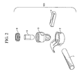
- FIG. 2 illustrates an exploded view of the spinal cross-connector assembly construct of FIG. 1 according to an embodiment herein;
- FIG. 3(A) illustrates a top view of a spinal cross-connector assembly according to an embodiment herein;
- FIG. 3(B) illustrates a bottom view of the spinal cross-connector assembly of FIG. 3 (A) according to an embodiment herein;
- FIG. 3(C) illustrates a cross-sectional view of the spinal cross-connector assembly of FIG. 3(B) cut along line A-A of FIG. 3(B) according to an embodiment herein;
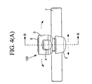
- FIG. 4(A) illustrates a back view of the spinal cross-connector assembly of FIG. 3(A) according to an embodiment herein;
- FIG. 4(B) illustrates a cross-sectional side view of the spinal cross-connector assembly of FIG. 4(A) cut along line B-B of FIG. 4(A) according to an embodiment herein;
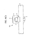
- FIG. 4(C) illustrates a back view of the spinal cross-connector assembly of FIG. 3(A) according to an embodiment herein;
- FIG. 5(A) illustrates a perspective view of the connector body of the spinal cross-connector assembly construct of FIG. 2 according to an embodiment herein;
- FIG. 5(B) illustrates a top view of the connector body of FIG. 5(A) according to an embodiment herein;
- FIG. 5(C) illustrates a front view of the connector body of FIG. 5(A) according to an embodiment herein;
- FIG. 5(D) illustrates a cross-sectional side view of the connector body of FIG. 5(A) cut along line C-C of FIG. 5(C) according to an embodiment herein;
- FIG. 5(E) illustrates a back view of the connector body of FIG. 5(A) cut along line D-D of FIG. 5(D) according to an embodiment herein;
- FIG. 6(A) illustrates a perspective view of the connector head of the spinal cross-connector assembly construct of FIG. 2 according to an embodiment herein;
- FIG. 6(B) illustrates a side view of the connector head of FIG. 6(A) according to an embodiment herein;
- FIG. 6(C) illustrates a cross-sectional top view of the connector head of FIG. 6(A) cut along line E-E of FIG. 6(B) according to an embodiment herein;
- FIG. 6(D) illustrates a cross-sectional front view of the connector head of FIG. 6(A) cut along line F-F of FIG. 6(B) according to an embodiment herein;
- FIG. 6(E) illustrates a cross-sectional side view of the connector head of FIG. 6(A) cut along line G-G of FIG. 6(D) according to an embodiment herein;
- FIG. 7(A) illustrates a perspective view of the bar of the spinal cross-connector assembly construct of FIG. 2 according to an embodiment herein;
- FIG. 7(B) illustrates a top view of the bar of FIG. 7(A) according to an embodiment herein;
- FIG. 7(C) illustrates a front view of the bar of FIG. 7(A) according to an embodiment herein;
- FIG. 7(D) illustrates a side view of the bar of FIG. 7(A) according to an embodiment herein;
- FIG. 8(A) illustrates a perspective view of the locking pin of the spinal cross-connector assembly construct of FIG. 2 according to an embodiment herein;
- FIG. 8(B) illustrates a side view of the locking pin of FIG. 8(A) according to an embodiment herein;
- FIG. 8(C) illustrates a top view of the locking pin of FIG. 8(A) according to an embodiment herein;
- FIG. 8(D) illustrates a cross-sectional side view of the locking pin of FIG. 8(A) cut along line H-H of FIG. 8(C) according to an embodiment herein;
- FIG. 9(A) illustrates a perspective view of the set screw of the spinal cross-connector assembly construct of FIG. 2 according to an embodiment herein;
- FIG. 9(B) illustrates a side view of the set screw of FIG. 9(A) according to an embodiment herein;
- FIG. 9(C) illustrates a top view of the set screw of FIG. 9(A) according to an embodiment herein;
- FIG. 9(D) illustrates a cross-sectional side view of the set screw of FIG. 9(A) cut along line I-I of FIG. 9(C) according to an embodiment herein;
- FIG. 10(A) illustrates an exploded view of a spinal cross-connector assembly construct according to an alternate embodiment herein;
- FIG. 10(B) illustrates a perspective view of the transverse member of the spinal cross-connector assembly construct of FIG. 10(A) according to an alternate embodiment herein;
- FIG. 10(C) illustrates a perspective view of the locking pin of the spinal cross-connector assembly construct of FIG. 10(A) according to an alternate embodiment herein;
- FIG. 10(D) illustrates a top view of the assembled spinal cross-connector assembly construct of FIG. 10(A) according to an alternate embodiment herein;
- FIG. 10(E) illustrates a cross-sectional side view of the spinal cross-connector assembly of FIG. 10(D) cut along line J-J of FIG. 10(D) according to an alternate embodiment herein;
- FIG. 10(F) illustrates a back view of the spinal cross-connector assembly of FIG. 10(E) cut along line K-K of FIG. 10(E) according to an alternate embodiment herein;
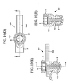
- FIG. 11(A) illustrates a perspective view of a spinal cross-connector assembly according to a second alternate embodiment herein;
- FIG. 11(B) illustrates an upper perspective view of the locking mechanism of the spinal cross-connector assembly of FIG. 11 (A) according to a second alternate embodiment herein;
- FIG. 11(C) illustrates a lower perspective view of the locking mechanism of the spinal cross-connector assembly of FIG. 11(A) according to a second alternate embodiment herein;
- FIG. 11(D) illustrates a top view of the spinal cross-connector assembly construct of FIG. 11(A) according to a second alternate embodiment herein;
- FIG. 11(E) illustrates a cross-sectional side view of the spinal cross-connector assembly of FIG. 11(A) cut along line L-L of FIG. 11(D) according to a second alternate embodiment herein;
- FIG. 11(F) illustrates a back view of the spinal cross-connector assembly of FIG. 11(A) cut along line M-M of FIG. 11(E) according to a second alternate embodiment herein;
- FIG. 12 is a flow diagram illustrating a method which can be carried out with an assembly according to the invention.
- FIGS. 1 through 12 where similar reference characters denote corresponding features consistently throughout the figures, there are shown preferred embodiments.
- FIG. 1 illustrates a spinal cross-connector assembly 1 according to an embodiment herein.
- the assembly 1 When used in a surgical procedure, the assembly 1 generally comprises two separate constructs 100 connected by a transverse member 4 (for example, a bar, rod, or other connecting member geometry).
- each of the constructs 100 comprises a connector body 2 operatively connected to a connector head 3, which is dimensioned and configured to receive a locking pin 5, a set screw 6, and the transverse member 4.
- the connector body 2 is dimensioned and configured to engage a longitudinal member 7 (for example, a rod, bar, or other geometries).
- a longitudinal member 7 for example, a rod, bar, or other geometries.
- both constructs 100 of the spinal cross-connector assembly 1 are placed on the opposing longitudinal members 7 of the spinal fusion construct.
- each construct 100 of the spinal cross-connector assembly 1 is polyaxial with respect to its motion relative to a fixed axis and as such may be adjusted for optimum placement within the spinal cavity (not shown).
- FIGS. 3(A) through 4(C) illustrate several views of one of the constructs 100 of the spinal cross-connector assembly 1 of FIG. 1 .
- the dotted arrows refer to the respective directions of the range of motion of the connector head 3 and transverse member 4.
- the heavy arrows at the bottom of FIG. 4(B) refer to the forces (i.e., compression) caused by the construct 100 when it engages the longitudinal member 7.
- the horizontal heavy arrows in FIG. 4(B) refer to the expanding forces, F e , of the connector head 3 while the heavy arrow that points down refers to the pushing force, F p , of the locking pin 5.
- FIG. 4(C) best illustrates the engagement of the longitudinal member 7 with the connector body 2.
- FIGS. 5(A) through 5(E) illustrate several views of the connector body 2 according to an embodiment herein.
- the connector body 2 is generally embodied as a one-piece construct (although multiple pieces fixed to one another are possible) and comprises a socket portion 8 attached to a longitudinal member receiving clip 9.
- the socket portion 8 comprises a generally hollowed inner socket 10 defined by an inner socket wall 15, an inner socket base 16, and an upper lip 13.
- An outer socket wall 14 provides the outer definition of the socket portion 8 of the connector body 2.
- the receiving clip 9 comprises a curved upper surface 11 having a concave portion 18 positioned on the underside of the curved upper surface 11.
- the concave portion 18 is dimensioned and configured to receive the longitudinal member 7 (of FIGS. 2 through 4(C) ).
- the inner socket base 16 of the socket portion 8 is generally circular in shape and it is on this base 16 where the connector head 3 and locking pin 5 (of FIGS. 1 through 4(C) ) rest.
- the inner socket base 16 further includes a gap 17, which creates a separation between the inner socket base 16 and a bias member 12 of the connector body 2.
- the bias member 12 may be configured as a spring, flange, or flexible structure.
- the gap 17 extends up to and in the receiving clip 9, and when viewed from the top (as in FIG. 5(B) ) the gap 17 may appear to be V-shaped although other shapes are possible, and the embodiments herein are not limited to any particular shape or geometry.
- the bias member 12 is an extension of the receiving clip 9 as it is retained in a cantilever manner to the connector body 2 only by the receiving clip 9 and does not contact the socket portion 8 due to the gap 17.
- the thickness of the gap 17 is uniform, but may include a slightly larger gap area towards the bottom of the gap 17 (i.e., bottom of the V-shape).
- FIG. 5(D) illustrates a cross-sectional side view of the connector body 2 of FIG. 5(A) taken along line C-C of FIG. 5(C) .
- the relative thicknesses of the socket portion 8 and receiving clip 9 can be seen as well as the relative depth of the gap 17.
- the configuration of the concave portion 18 of the receiving clip 9 can be seen as generally matching the cylindrical configuration of the longitudinal member 7 (of FIGS. 2 through 4(C) ).
- FIG. 5(E) illustrates a back view of the connector body 2 of FIG. 5(A) taken along line D-D of FIG. 5(D) , and further illustrates the general configuration of the gap 17.
- FIGS. 6(A) through 6(E) illustrate several views of the connector head 3 of the spinal cross-connector assembly construct 100 of FIG. 2 according to an embodiment herein.
- the connector head 3 is a one-piece construct (although multiple pieces fixed to one another are possible) and comprises an upper portion 19 connected to a lower bulbous end 20.
- the upper portion 19 is defined by a generally curved outer wall 21 having an upper cavity hole 22 and a bar receiving hole 23 configured therein.
- the upper cavity hole 22 is positioned along a longitudinal axis of the connector head 3 and the bar receiving hole 23 is positioned along an axis transverse to the longitudinal axis of the connector head 3, and thus the upper cavity hole 22 is preferably transverse to the bar receiving hole 23.
- the bar receiving hole 23 extends through the outer wall 21 of the connector head 3 and the upper cavity hole 22 extends longitudinally through the connector head 3 and terminates with an opening 26 at the bottom of the bulbous end 20 of the connector head 3.
- Threads 28 are configured in the upper portion 19 of the connector head 3 and are dimensioned and configured to receive the set screw 6 (of FIGS. 1 through 4(C) ).
- An inner connector base 27 generally separates the upper portion 19 of the connector head 3 from the bulbous end 20 of the connector head 3, wherein the inner connector base 27 is preferably flat to facilitate an even positioning of the transverse member 4 (of FIGS. 1 through 4(C) ).
- the bulbous end 20 preferably comprises a generally spherical configuration having a plurality of downward-turned prongs 24 spaced apart from one another by slots 2S. The prongs 24 are flexible to allow expansion of the bulbous end 20 of the connector head 3 into the inner socket 10 of the connector body 2.
- a pin cavity 29 is configured in the bulbous end 20 of the connector head 3 to accommodate the locking pin 5 (of FIGS. 2 through 4(C) ), wherein the upper part of the pin cavity 29 begins at the position of the inner connector base 27, and the lower part of the pin cavity 29 terminates at the opening 26 in the bulbous end 20 of the connector head 3.
- FIG. 6(C) illustrates a cross-sectional top view of the connector head 3 of FIG. 6(A) taken along line E-E of FIG. 6(B) .
- FIG. 6(D) illustrates a cross-sectional front view of the connector head 3 of FIG. 6(A) taken along line F-F of FIG. 6(B)
- FIG. 6(E) illustrates a cross-sectional side view of the connector head 3 of FIG. 6(A) cut along line G-G of FIG. 6(D) .
- the threads 28 and pin cavity 29 can best be seen.
- FIGS. 7(A) through 7(D) illustrate several views of the transverse member 4 (of FIGS. 1 through 4(C) ) according to an embodiment herein.
- the transverse member 4 generally comprises a generally uniform elongated one-piece body 30 (although multiple pieces fixed to one another are possible) with a pair of distal ends 31, 32 comprising a first end 31 distally located to a second end 32.
- the transverse member 4 is dimensioned and configured to fit through the bar receiving hole 23 of the connector head 3 and rest on the inner socket base 16 of the connector head 3 (of FIGS. 6(A) through 6(E) ).
- the bar receiving hole 23 may be configured to snugly fit the transverse member 4, or alternatively, the bar receiving hole 23 may be configured wider than the width of the transverse member 4 to allow for some "slop" for additional range of motion of the transverse member 4.
- FIGS. 8(A) through 8(D) illustrate several views of the locking pin 5 of the spinal cross-connector assembly construct 100 of FIG. 2 according to an embodiment herein.
- the locking pin 5 is preferably embodied as a one-piece construct (although multiple pieces fixed to one another are possible).
- the locking pin 5 comprises a lower end 33 terminating with a tip 39. Extending from the lower end 33 and distally away from the tip 39 is a plurality of upper members 34 separated from one another by slots 36.
- the shape of the upper members 34 follows the contour of the shape of the lower end 33 of the locking pin 5, wherein the overall contour of the locking pin 5 is dimensioned and configured to fit into the pin cavity 29 of the connector head 3 (of FIGS. 6(D) and 6(E) ).
- a central hole 35 is configured in the locking pin 5 and in between the plurality of upper members 34 such that the combination of the central hole 35 and slots 36 create prong-like upper members 34.
- the central hole 35 terminates with a central hole base 38, which acts as a positional separation between the lower end 33 of the locking pin 5 and the upper members 34 of the locking pin 5.
- a lip 37 is configured on each of the upper members 34, wherein the lips 37 of all of the upper members 34 are aligned to one another to form a substantially circular shape when viewed from the top as illustrated in FIG. 8(C) .
- the lips 37 of the upper members 34 are adapted to lock the locking pin 5 into connector head 3 (of FIGS.
- FIG. 8(D) illustrates a cross-sectional side view of the locking pin 5 of FIG. 8(A) taken along line H-H of FIG. 8(C) .
- the edges 42 of the upper members 34 can be seen as well as the preferred conical shape (although other shapes are possible) of the central hole base 38.
- FIGS. 9(A) through 9(D) illustrate several views of the set screw 6 of the spinal cross-connector assembly 1 of FIG. 1 according to an embodiment herein.
- the set screw 6 may be any type of blocker used to retain the transverse member 4 and locking pin 5 in place in the connector head 3 (of FIGS. 2 through 4(C) ).
- the set screw 6 comprises threads 40 positioned around an outer periphery of the set screw 6 and dimensioned and configured to engage the threads 28 of the connector head 3 (of FIGS. 6(D) and 6(E) ).
- the set screw 6 comprises a fastening feature 41, which may be configured to accommodate a screwdriver (hex, torx, flat-head, Phillips, etc.) or similar mechanism.
- a screwdriver hexagon, torx, flat-head, Phillips, etc.
- FIG. 9(D) illustrates a cross-sectional side view of the set screw 6 of FIG. 9(A) cut along line 1-1 of FIG. 9(C) , which further shows the inner wall 43 of the set screw 6.
- the transverse member 4 is bendable and may be bent if desired to avoid interference with the spinal anatomy (not shown). Moreover, the bendable transverse member 4 may be cut to length if desired to avoid protrusion into soft tissue or can be pre-cut and pre-assembled to various sizes. Furthermore, each polyaxial connector head 3 is locked into place by its internal preloaded set screw 6.
- the set screw 6 locks the polyaxial connector head 3 into position as well as the connector body 2 to the longitudinal member 7 all in one locking step. This occurs by placing the bulbous end 20 of the connector head 3 into the inner socket 10 of the socket portion 8 of the connector body 2. Next, the locking pin 5 is placed into the pin cavity 29 (lower end 33 of the locking pin 5 is placed first) of the connector head 3. Then, the transverse member 4 is placed in the bar receiving hole 23 of the connector head 3. Thereafter, the longitudinal member 7 is placed into position in the concave portion 18 of the receiving clip 9 of the connector body 2.
- the set screw 6 is fastened into place in the connector head 3 with the threads 40 of the set screw 6 engaging the threads 28 of the connector head 3.
- the tightening of the set screw 6 causes the body 30 of the transverse bar 4 to exert a force on upper members 34 of the locking pin 5, which causes the tip 39 of the lower end 33 of the locking pin 5 to exert a force on the prongs 24 of the bulbous end 20 of the connector head 3, which causes the bulbous end 20 of the connector head 3 to expand in the inner socket 10 of the socket portion 8 of the connector body 2.
- This also causes the tip 39 to protrude through the opening 26 of the bulbous end 20 of the connector head 3.
- the construct 100 may include a slightly altered transverse member 104 and locking pin 105 as shown in FIG. 10(A) .
- the connector head 3 fits into the connector body 2 as with the previous embodiment.
- the transverse member 104 includes a slot 106 configured in each distal end 31, 32 of the transverse member 104.
- FIG. 10(C) illustrates a perspective view of the alternate locking pin 105, which comprises a generally planar upper portion 107 and a stem portion 108 extending from the upper portion 107.
- the stem portion 108 ends with a generally tapered section 109.
- the locking pin 105 is configured to fit into the pin cavity 29, which is configured in the bulbous end 20 of the connector head 3 (of FIGS. 6(D) and 6(E) ).
- the transverse member 104 is inserted into the bar receiving hole 23 of the connector head 3 and the locking pin 105 is inserted in the connector head 3 and through the slot 106 of the transverse member 104.
- the set screw 6 is then connected to the connector head 3.
- This embodiment allows for a more secured locking of the transverse member 104 into place in the connector head 3.
- the width and length of the slot 106 is preferably configured larger than the diameter of the locking pin 105 so as to allow for an adjustable positioning of the transverse member 104 in the connector head 3.
- the positioning of the locking pin 105 with respect to the transverse member 104 is best shown in FIGS. 10(E) and 10(F) where the side view of FIG.
- FIG. 10(E) is taken along line J-J of FIG. 10(D) and the back view of FIG. 10(F) is taken along line K-K of FIG. 10(E) .
- the manner of the bulbous end 20 of the connector head 3 expanding in the connector body 2 due to the insertion of the locking pin 105 and clamping force of the set screw 6 thereby causing actuation of the bias member 12 is similar in the alternate embodiment as it was for the preferred embodiment.
- FIGS. 11(A) through 11(F) Still another alternate embodiment is illustrated in FIGS. 11(A) through 11(F) .
- a combined locking mechanism 205 is provided to fit through the slot 106 of the transverse member 104 and fit into the connector head 3 and engage the connector body 2.
- the locking mechanism 205 is preferably configured as a one-piece structure (either threaded together or molded together) comprising an upper blocker portion 206 and a stem portion 208 extending from the blocker portion 206.
- the stem portion 208 terminates with a generally tapered end 209.
- the manner of the bulbous end 20 of the connector head 3 expanding in the connector body 2 due to the insertion and clamping force of the locking mechanism 105 thereby causing actuation of the bias member 12 is similar in the second alternate embodiment as it was for the preferred embodiment and the first alternate embodiment.
- the second alternate embodiment allows for fewer component parts and an easier assembly process.
- the positioning of the locking pin 205 with respect to the transverse member 104 is best shown in FIGS. 11(E) and 11(F) where the side view of FIG. 11(E) is taken along line L-L of FIG. 11(D) and the back view of FIG. 11(F) is taken along line M-M of FIG. 11(E) .
- the geometry of the connector body 2 may be modified for customized angle placement of the longitudinal member 7 on the connector body 2.
- the inner socket 10 of the connector body 2 may be positioned at various locations in the connector body 2 to provide varied offsets or heights of initial position for the assembly 1.
- the elongated connecting transverse member 4 may be dimensioned and configured to fit over the connector head 3 and be locked by the set screw 6.
- the materials for all components in the assembly 1 may comprise any suitable grades of metal, polymers, or shape-memory materials.
- FIG. 12 illustrates a flow diagram of a method of locking a longitudinal member 7 to a cross-connector assembly construct 100, wherein the method comprises positioning (301) a longitudinal member 7 adjacent to a flexible clip 2; setting (303) a housing component 3 in the flexible clip 2; inserting (305) a pin 5 in the housing component 3, wherein the pin 5 contacts the flexible clip 2; inserting (307) a connecting member 4 in the housing component 3; and attaching (309) a locking mechanism 6 to the housing component 3, wherein the locking mechanism 6 is operatively connected to the pin 5.
- attachment of the locking mechanism 6 to the housing component 3 causes the pin 5 to engage the flexible clip 2 thereby causing the flexible clip 2 to lock the longitudinal member 7 into position.
- the flexible clip 2 preferably comprises a flexible bias member 12, and wherein the flexible bias member 12 is adapted to lock the longitudinal member 7 into position.
- the flexible clip 2 comprises a socket portion 8 and a clip portion 9 attached to the socket portion 8, wherein the flexible bias member 12 extends from the clip portion 9 to a bottom region 16 of the socket portion 8, and wherein the clip portion 9 retains the longitudinal member 7 into position.
- the housing component 3 comprises an upper portion 19 connected to a bulbous end 20, wherein the upper portion 19 comprises a first hole 22 adapted to engage the locking mechanism 6; and a second hole 23 adapted to accommodate the connecting member 4, wherein the first hole 22 and the second hole 23 are transversely positioned with respect to one another, wherein the bulbous end 20 comprises a plurality of flexible prongs 24 separated from one another by slots 25; and an opening 26 extending through the bulbous end 20 and extending to the first hole 22, wherein the pin 5 is adapted to engage the plurality of flexible prongs 24 causing the plurality of flexible prongs 24 to outwardly bend and lock the housing component 3 to the flexible clip 2.
- the method may further comprise connecting a pair of cross-connector assembly constructs 100 using the connecting member 4.
- the connecting member 4 may comprise a slot 106, and wherein the method further comprises inserting the pin 5 through the slot 106 of the connecting member 4.
- the embodiments herein provide a polyaxial cross-connector (transverse connector / rod crosslink) assembly 1 adapted to connect the longitudinal members 7 of a spinal fusion construct 100 in an easy an efficient manner.
- the embodiments herein augment the conventional assemblies by providing an assembly that is stiffer and stronger under torsional loads than conventional designs.
- the assembly 1 generally comprises a flexible clip 9 with a socket 10 adapted to receive the polyaxial connector head 2 which houses the bendable transverse member 4.
- the embodiments herein have a minimum of two to a maximum of nine degrees (and preferably six degrees) of freedom depending on whether the bendable transverse member 4 is embodied as a rod or bar.
- the assembly 1 may be packaged pre-assembled prior to use during surgery.
Landscapes
- Health & Medical Sciences (AREA)
- Orthopedic Medicine & Surgery (AREA)
- Life Sciences & Earth Sciences (AREA)
- Neurology (AREA)
- Surgery (AREA)
- Heart & Thoracic Surgery (AREA)
- Engineering & Computer Science (AREA)
- Biomedical Technology (AREA)
- Nuclear Medicine, Radiotherapy & Molecular Imaging (AREA)
- Medical Informatics (AREA)
- Molecular Biology (AREA)
- Animal Behavior & Ethology (AREA)
- General Health & Medical Sciences (AREA)
- Public Health (AREA)
- Veterinary Medicine (AREA)
- Surgical Instruments (AREA)
- Prostheses (AREA)
- Coupling Device And Connection With Printed Circuit (AREA)
Claims (6)
- Spinale Kreuzverbinderanordnung (1) zum Verbinden eines longitudinalen Elements (7) und eines länglichen transversalen Elements (4, 104), wobei die Anordnung (1) aufweist:einen Verbinderkörper (2) aufweisend:einen Aufnahmeteilbereich (8), aufweisend eine offene Oberseite, einen konkaven inneren Aufnahmeteilbereich (10), und eine im Wesentlichen geschlossene untere Basis (16);einen flexiblen aufnehmenden Schellenteilbereich (9) benachbart zu einer Seite des Aufnahmeteilbereichs (8); undein flexibles schiefes Element (12), das sich in Bezug auf den flexiblen aufnehmenden Schellenteilbereich (9) biegt und sich von dem flexiblen aufnehmenden Schellenteilbereich (9) zu der unteren Basis (16) des Aufnahmeteilbereichs (8) erstreckt, so dass das flexible schiefe Element (12) strukturell von der unteren Basis (16) des Aufnahmeteilbereichs (8) durch eine Lücke (17) getrennt ist;einen Verbinderkopf (3), der in den Verbinderkörper (2) eingreift, wobei der Verbinderkopf (3) aufweist:einen oberen Teilbereich (19), aufweisend:eine erste Öffnung (22), die in einen Blockierer (6) eingreift;
undeine zweite Öffnung (23), die ein längliches transversales Element (4, 104) aufnimmt, wobei die erste Öffnung (22) und die zweite Öffnung (23) transversal in Bezug aufeinander positioniert sind;einen unteren Teilbereich, der ein nach außen herausragendes und ausdehnbares sphärisches bauchiges Ende (20) aufweist, das in den Aufnahmeteilbereich des Verbinderkörpers (2) hineinpasst, und wobei der Aufnahmeteilbereich (8) das bauchige Ende (20) mit dem konkaven inneren Aufnahmeteilbereich (10) umschließt, wobei das bauchige Ende (20) aufweist:eine Mehrzahl von flexiblen Zacken (24), die voneinander durch Schlitze (25) getrennt sind; undeine dritte Öffnung (26, 29), die sich durch das bauchige Ende (20) erstreckt und sich zu der ersten Öffnung (22) erstreckt; undeinen Stift (5), der wirkend mit dem Verbinderkörper (2) und dem Verbinderkopf (3) verbunden ist,wobei ein längliches transversales Element (4, 104) wirkend mit dem Verbinderkopf (3) und dem Stift (5) verbunden ist, undwobei ein Blockierer (6) wirkend mit dem Verbinderkopf (3) und dem länglichen transversalen Element (4) verbunden ist. - Spinale Kreuzverbinderanordnung (1) gemäß Anspruch 1, weiterhin aufweisend ein longitudinales Element (7), das an dem Verbinderkörper (2) arretiert ist, wobei das flexible schiefe Element (12) das longitudinale Element (7) an dem flexiblen aufnehmenden Schellenteilbereich (9) festhält.
- Spinale Kreuzverbinderanordnung (1) gemäß Anspruch 2, wobei der flexible aufnehmende Schellenteilbereich (9) das longitudinale Element (7) festhält, und wobei das flexible schiefe Element dimensioniert und eingerichtet ist, um eine Form des flexiblen aufnehmenden Schellenteilbereichs (9) und des Aufnahmeteilbereichs (8) nachzuformen.
- Spinale Kreuzverbinderanordnung (1) gemäß Anspruch 2, wobei der Stift (5) in das flexible schiefe Element (12) eingreift, wodurch bewirkt wird, dass sich das flexible schiefe Element (12) von dem Verbinderkörper (2) wegerstreckt, und wodurch bewirkt wird, dass das longitudinale Element (7) an dem Verbinderkörper (2) arretiert wird.
- Spinale Kreuzverbinderanordnung (1) gemäß Anspruch 1, wobei der Stift (5) in die Mehrzahl von flexiblen Zacken (24) eingreift, wodurch bewirkt wird, dass sich die Mehrzahl von flexiblen Zacken (24) nach außen verbiegt und das bauchige Ende (20) des Verbinderkopfs (3) an dem konkaven inneren Aufnahmeteilbereich (10) arretiert.
- Spinale Kreuzverbinderanordnung (1) gemäß Anspruch 1, wobei das längliche transversale Element (104) einen Schlitz (106) aufweist, der den Stift (5) aufnimmt.
Applications Claiming Priority (2)
| Application Number | Priority Date | Filing Date | Title |
|---|---|---|---|
| US11/373,386 US7780704B2 (en) | 2006-03-10 | 2006-03-10 | Spinal cross-connector |
| PCT/US2006/021015 WO2007106104A1 (en) | 2006-03-10 | 2006-05-31 | Spinal cross-connector |
Publications (3)
| Publication Number | Publication Date |
|---|---|
| EP1996098A1 EP1996098A1 (de) | 2008-12-03 |
| EP1996098A4 EP1996098A4 (de) | 2010-01-13 |
| EP1996098B1 true EP1996098B1 (de) | 2011-02-23 |
Family
ID=38479907
Family Applications (1)
| Application Number | Title | Priority Date | Filing Date |
|---|---|---|---|
| EP06771661A Not-in-force EP1996098B1 (de) | 2006-03-10 | 2006-05-31 | Wirbelsäulen-querverbinder |
Country Status (6)
| Country | Link |
|---|---|
| US (1) | US7780704B2 (de) |
| EP (1) | EP1996098B1 (de) |
| JP (1) | JP2009528881A (de) |
| AT (1) | ATE499058T1 (de) |
| DE (1) | DE602006020350D1 (de) |
| WO (1) | WO2007106104A1 (de) |
Families Citing this family (57)
| Publication number | Priority date | Publication date | Assignee | Title |
|---|---|---|---|---|
| US8480712B1 (en) | 2004-01-06 | 2013-07-09 | Nuvasive, Inc. | System and method for performing spinal fixation |
| US8728132B2 (en) | 2004-04-20 | 2014-05-20 | James L. Chappuis | Internal pedicle insulator apparatus and method of use |
| US20070156241A1 (en) | 2004-08-09 | 2007-07-05 | Reiley Mark A | Systems and methods for the fixation or fusion of bone |
| US9662158B2 (en) | 2004-08-09 | 2017-05-30 | Si-Bone Inc. | Systems and methods for the fixation or fusion of bone at or near a sacroiliac joint |
| US8388667B2 (en) | 2004-08-09 | 2013-03-05 | Si-Bone, Inc. | Systems and methods for the fixation or fusion of bone using compressive implants |
| US20180228621A1 (en) | 2004-08-09 | 2018-08-16 | Mark A. Reiley | Apparatus, systems, and methods for the fixation or fusion of bone |
| US8414648B2 (en) | 2004-08-09 | 2013-04-09 | Si-Bone Inc. | Apparatus, systems, and methods for achieving trans-iliac lumbar fusion |
| US8425570B2 (en) | 2004-08-09 | 2013-04-23 | Si-Bone Inc. | Apparatus, systems, and methods for achieving anterior lumbar interbody fusion |
| US8444693B2 (en) | 2004-08-09 | 2013-05-21 | Si-Bone Inc. | Apparatus, systems, and methods for achieving lumbar facet fusion |
| US9949843B2 (en) | 2004-08-09 | 2018-04-24 | Si-Bone Inc. | Apparatus, systems, and methods for the fixation or fusion of bone |
| US20070225712A1 (en) * | 2004-10-20 | 2007-09-27 | Moti Altarac | Systems and methods for posterior dynamic stabilization of the spine |
| GB0521582D0 (en) | 2005-10-22 | 2005-11-30 | Depuy Int Ltd | An implant for supporting a spinal column |
| GB0600662D0 (en) | 2006-01-13 | 2006-02-22 | Depuy Int Ltd | Spinal support rod kit |
| US8348952B2 (en) | 2006-01-26 | 2013-01-08 | Depuy International Ltd. | System and method for cooling a spinal correction device comprising a shape memory material for corrective spinal surgery |
| WO2008040134A1 (de) * | 2006-10-02 | 2008-04-10 | Cendres+Métaux Sa | Verankerung zur befestigung eines zahnersatzes |
| US7744632B2 (en) * | 2006-12-20 | 2010-06-29 | Aesculap Implant Systems, Inc. | Rod to rod connector |
| GB0720762D0 (en) | 2007-10-24 | 2007-12-05 | Depuy Spine Sorl | Assembly for orthopaedic surgery |
| US8998958B2 (en) * | 2007-12-20 | 2015-04-07 | Aesculap Implant Systems, Llc | Locking device introducer instrument |
| US9060813B1 (en) | 2008-02-29 | 2015-06-23 | Nuvasive, Inc. | Surgical fixation system and related methods |
| US9095380B2 (en) * | 2009-03-31 | 2015-08-04 | Hamid R. Mir | Spinous process cross-link |
| CA2759249A1 (en) * | 2009-04-23 | 2010-10-28 | Spinal Elements, Inc. | Transverse connectors |
| US20100291507A1 (en) * | 2009-05-13 | 2010-11-18 | Custom Spine, Inc. | Polyaxial Dental Implant |
| US8372120B2 (en) | 2009-05-20 | 2013-02-12 | Spine Wave, Inc. | Multi-axial cross connector |
| US8246657B1 (en) | 2009-06-29 | 2012-08-21 | Nuvasive, Inc. | Spinal cross connector |
| US9381044B2 (en) | 2010-01-26 | 2016-07-05 | Pioneer Surgical Technology, Inc. | Posterior spinal stabilization plate device |
| US9198696B1 (en) | 2010-05-27 | 2015-12-01 | Nuvasive, Inc. | Cross-connector and related methods |
| US8920471B2 (en) | 2010-07-12 | 2014-12-30 | K2M, Inc. | Transverse connector |
| US9387013B1 (en) | 2011-03-01 | 2016-07-12 | Nuvasive, Inc. | Posterior cervical fixation system |
| US9247964B1 (en) | 2011-03-01 | 2016-02-02 | Nuasive, Inc. | Spinal Cross-connector |
| US8672978B2 (en) | 2011-03-04 | 2014-03-18 | Zimmer Spine, Inc. | Transverse connector |
| US8852241B2 (en) * | 2011-08-04 | 2014-10-07 | Devin Datta | Surgical devices and methods providing sacroiliac stabilization |
| US9655655B2 (en) | 2011-08-16 | 2017-05-23 | Aesculap Implant Systems, Llc | Two step locking screw assembly |
| US10363140B2 (en) | 2012-03-09 | 2019-07-30 | Si-Bone Inc. | Systems, device, and methods for joint fusion |
| EP2822490A4 (de) | 2012-03-09 | 2016-03-02 | Si Bone Inc | Integriertes implantat |
| EP2846705B1 (de) | 2012-05-04 | 2018-12-26 | SI-Bone, Inc. | Fenestriertes implantat |
| JP6189939B2 (ja) * | 2012-05-11 | 2017-08-30 | オーソペディアトリクス・コーポレーション | 外科用連結器および器具類 |
| US9339309B1 (en) | 2012-10-11 | 2016-05-17 | Nuvasive, Inc. | Systems and methods for inserting cross-connectors |
| US9072547B2 (en) * | 2012-11-06 | 2015-07-07 | Globus Medical, Inc. | Polyaxial cross connector |
| US9936983B2 (en) | 2013-03-15 | 2018-04-10 | Si-Bone Inc. | Implants for spinal fixation or fusion |
| US11147688B2 (en) | 2013-10-15 | 2021-10-19 | Si-Bone Inc. | Implant placement |
| WO2015057866A1 (en) | 2013-10-15 | 2015-04-23 | Si-Bone Inc. | Implant placement |
| US9662157B2 (en) | 2014-09-18 | 2017-05-30 | Si-Bone Inc. | Matrix implant |
| US10166033B2 (en) | 2014-09-18 | 2019-01-01 | Si-Bone Inc. | Implants for bone fixation or fusion |
| US10376206B2 (en) | 2015-04-01 | 2019-08-13 | Si-Bone Inc. | Neuromonitoring systems and methods for bone fixation or fusion procedures |
| AU2017302286B2 (en) * | 2016-07-26 | 2022-08-18 | Orthopediatrics Corp. | Orthopedic tethered implants and system |
| US11116519B2 (en) | 2017-09-26 | 2021-09-14 | Si-Bone Inc. | Systems and methods for decorticating the sacroiliac joint |
| ES3011907T3 (en) | 2018-03-28 | 2025-04-08 | Si Bone Inc | Threaded implants for use across bone segments |
| US11369419B2 (en) | 2019-02-14 | 2022-06-28 | Si-Bone Inc. | Implants for spinal fixation and or fusion |
| JP2022520101A (ja) | 2019-02-14 | 2022-03-28 | エスアイ-ボーン・インコーポレイテッド | 脊椎の固定及び、又は融合のためのインプラント |
| WO2021102429A1 (en) | 2019-11-21 | 2021-05-27 | Si-Bone Inc. | Rod coupling assemblies for bone stabilization constructs |
| ES3042147T3 (en) | 2019-11-27 | 2025-11-18 | Si Bone Inc | Bone stabilizing implants across si joints |
| AU2020402850A1 (en) | 2019-12-09 | 2022-06-09 | Si-Bone Inc. | Sacro-iliac joint stabilizing implants and methods of implantation |
| EP4259015A4 (de) | 2020-12-09 | 2024-09-11 | SI-Bone, Inc. | Kreuzdarmbeingelenk-stabilisierende implantate und implantationsverfahren |
| US11331125B1 (en) | 2021-10-07 | 2022-05-17 | Ortho Inventions, Llc | Low profile rod-to-rod coupler |
| EP4440505A4 (de) | 2021-12-03 | 2025-11-19 | Si Bone Inc | Fusionskäfige und verfahren zur stabilisierung des kreuzdarmgelenks |
| US20240299065A1 (en) * | 2023-03-08 | 2024-09-12 | Nuvasive, Inc. | Percutaneous posterior fixation |
| WO2025038769A1 (en) | 2023-08-15 | 2025-02-20 | Si-Bone Inc. | Pelvic stabilization implants, methods of use and manufacture |
Family Cites Families (35)
| Publication number | Priority date | Publication date | Assignee | Title |
|---|---|---|---|---|
| CH271970A (de) * | 1948-06-21 | 1950-11-30 | Kobler & Co | Baukasten. |
| US3054321A (en) * | 1959-07-15 | 1962-09-18 | Macchia Anthony | Screw assembly with ball and socket connection |
| US5100420A (en) * | 1989-07-18 | 1992-03-31 | United States Surgical Corporation | Apparatus and method for applying surgical clips in laparoscopic or endoscopic procedures |
| US5312405A (en) * | 1992-07-06 | 1994-05-17 | Zimmer, Inc. | Spinal rod coupler |
| US5334203A (en) * | 1992-09-30 | 1994-08-02 | Amei Technologies Inc. | Spinal fixation system and methods |
| US5330473A (en) * | 1993-03-04 | 1994-07-19 | Advanced Spine Fixation Systems, Inc. | Branch connector for spinal fixation systems |
| US5522816A (en) * | 1994-03-09 | 1996-06-04 | Acromed Corporation | Transverse connection for spinal column corrective devices |
| US5601552A (en) * | 1994-03-18 | 1997-02-11 | Sofamor, S.N.C. | Fixing device for a rigid transverse connection device between rods of a spinal osteosynthesis system |
| US5498263A (en) * | 1994-06-28 | 1996-03-12 | Acromed Corporation | Transverse connector for spinal column corrective devices |
| US5688272A (en) * | 1995-03-30 | 1997-11-18 | Danek Medical, Inc. | Top-tightening transverse connector for a spinal fixation system |
| US5727899A (en) * | 1996-09-13 | 1998-03-17 | Minnesota Scientific, Inc. | Fulcrum clamp |
| US5735851A (en) * | 1996-10-09 | 1998-04-07 | Third Millennium Engineering, Llc | Modular polyaxial locking pedicle screw |
| JP2002514100A (ja) * | 1996-10-24 | 2002-05-14 | スピナル コンセプツ,インク. | 脊椎を固定するための方法および装置 |
| US6783526B1 (en) * | 1997-05-15 | 2004-08-31 | Howmedica Osteonics Corp. | Transverse rod connector clip |
| US6030389A (en) * | 1997-08-04 | 2000-02-29 | Spinal Concepts, Inc. | System and method for stabilizing the human spine with a bone plate |
| CA2343327C (en) * | 1998-09-11 | 2003-02-11 | Synthes (U.S.A.) | Variable angle spinal fixation system |
| DE19914232B4 (de) * | 1999-03-29 | 2012-08-30 | Signus Medizintechnik Gmbh | Vorrichtung zum Stabilisieren von Wirbelkörpern einer Wirbelsäule |
| DE60037352T2 (de) * | 1999-03-30 | 2008-11-13 | Howmedica Osteonics Corp. | Apparat zur Stabilisierung der Wirbelsäule |
| US6283967B1 (en) * | 1999-12-17 | 2001-09-04 | Synthes (U.S.A.) | Transconnector for coupling spinal rods |
| US6217578B1 (en) * | 1999-10-19 | 2001-04-17 | Stryker Spine S.A. | Spinal cross connector |
| NZ520002A (en) | 2000-01-13 | 2004-03-26 | Synthes Ag | Device for releasably clamping a longitudinal carrier in a surgical implant |
| US6432108B1 (en) * | 2000-01-24 | 2002-08-13 | Depuy Orthopaedics, Inc. | Transverse connector |
| US6235033B1 (en) * | 2000-04-19 | 2001-05-22 | Synthes (Usa) | Bone fixation assembly |
| US6524310B1 (en) * | 2000-08-18 | 2003-02-25 | Blackstone Medical, Inc. | Surgical cross-connecting apparatus having locking lever |
| US20030125750A1 (en) * | 2001-11-05 | 2003-07-03 | Zwirnmann Ralph Fritz | Spring loaded fixation element insertion device |
| US6793657B2 (en) * | 2001-09-10 | 2004-09-21 | Solco Biomedical Co., Ltd. | Spine fixing apparatus |
| FR2835734B1 (fr) * | 2002-02-11 | 2004-10-29 | Scient X | Systeme de liaison entre une tige rachidienne et une barre transversale |
| US7163538B2 (en) * | 2002-02-13 | 2007-01-16 | Cross Medical Products, Inc. | Posterior rod system |
| US7066938B2 (en) * | 2002-09-09 | 2006-06-27 | Depuy Spine, Inc. | Snap-on spinal rod connector |
| DE20314297U1 (de) * | 2003-09-12 | 2003-11-20 | AlloCon GmbH, 42929 Wermelskirchen | Knochenschraube |
| US7819902B2 (en) * | 2004-02-27 | 2010-10-26 | Custom Spine, Inc. | Medialised rod pedicle screw assembly |
| US7163539B2 (en) * | 2004-02-27 | 2007-01-16 | Custom Spine, Inc. | Biased angle polyaxial pedicle screw assembly |
| US20050228377A1 (en) * | 2004-04-07 | 2005-10-13 | Depuy Spine, Inc. | Spinal cross-connectors |
| US7377922B2 (en) * | 2004-04-15 | 2008-05-27 | Warsaw Orthopedic, Inc. | Transfer ring for offset tapered 3D connector |
| US7628799B2 (en) * | 2005-08-23 | 2009-12-08 | Aesculap Ag & Co. Kg | Rod to rod connector |
-
2006
- 2006-03-10 US US11/373,386 patent/US7780704B2/en not_active Expired - Fee Related
- 2006-05-31 JP JP2008558246A patent/JP2009528881A/ja not_active Ceased
- 2006-05-31 EP EP06771661A patent/EP1996098B1/de not_active Not-in-force
- 2006-05-31 WO PCT/US2006/021015 patent/WO2007106104A1/en not_active Ceased
- 2006-05-31 AT AT06771661T patent/ATE499058T1/de not_active IP Right Cessation
- 2006-05-31 DE DE602006020350T patent/DE602006020350D1/de active Active
Also Published As
| Publication number | Publication date |
|---|---|
| US20070213721A1 (en) | 2007-09-13 |
| JP2009528881A (ja) | 2009-08-13 |
| EP1996098A1 (de) | 2008-12-03 |
| ATE499058T1 (de) | 2011-03-15 |
| DE602006020350D1 (de) | 2011-04-07 |
| EP1996098A4 (de) | 2010-01-13 |
| WO2007106104A1 (en) | 2007-09-20 |
| US7780704B2 (en) | 2010-08-24 |
Similar Documents
| Publication | Publication Date | Title |
|---|---|---|
| EP1996098B1 (de) | Wirbelsäulen-querverbinder | |
| US7833248B2 (en) | Spinal cross-connector | |
| US7695500B2 (en) | Polyaxial occipital plate | |
| US7892257B2 (en) | Spring loaded, load sharing polyaxial pedicle screw assembly and method | |
| US9629663B2 (en) | Rod attachment for head to head cross connector | |
| US9351767B2 (en) | Supplementary spinal fixation/stabilization apparatus with dynamic inter-vertebral connection | |
| EP2693965B1 (de) | Klemme für eine wirbelsäulen-querverbindungsvorrichtung | |
| US20070005064A1 (en) | Intervertebral prosthetic device for spinal stabilization and method of implanting same | |
| US20070233068A1 (en) | Intervertebral prosthetic assembly for spinal stabilization and method of implanting same | |
| US20080208256A1 (en) | Pedicle based spinal stabilization with adjacent vertebral body support | |
| US20110160778A1 (en) | Poly-Axial Implant Fixation System | |
| JP2008502428A (ja) | 脊椎インプラント固定アセンブリ | |
| JP2009502234A (ja) | 融合構造体を伸長させるためのロッド伸長体 | |
| JP2010506684A (ja) | 中央ロッドコネクタとt字ロッド | |
| EP3900654B1 (de) | Knochenverankerungsvorrichtung | |
| AU2025283645A1 (en) | Laminoplasty Implant and Method of Use | |
| CN114052879A (zh) | 骨锚固装置 | |
| KR100952753B1 (ko) | 다이나믹 로드 | |
| JP2007152115A (ja) | 部分的接触のロッド接触部を備えた箱形チャンバ | |
| KR20060079213A (ko) | 종단 지지체 |
Legal Events
| Date | Code | Title | Description |
|---|---|---|---|
| PUAI | Public reference made under article 153(3) epc to a published international application that has entered the european phase |
Free format text: ORIGINAL CODE: 0009012 |
|
| 17P | Request for examination filed |
Effective date: 20081008 |
|
| AK | Designated contracting states |
Kind code of ref document: A1 Designated state(s): AT BE BG CH CY CZ DE DK EE ES FI FR GB GR HU IE IS IT LI LT LU LV MC NL PL PT RO SE SI SK TR |
|
| A4 | Supplementary search report drawn up and despatched |
Effective date: 20091215 |
|
| 17Q | First examination report despatched |
Effective date: 20091216 |
|
| GRAP | Despatch of communication of intention to grant a patent |
Free format text: ORIGINAL CODE: EPIDOSNIGR1 |
|
| RAP1 | Party data changed (applicant data changed or rights of an application transferred) |
Owner name: CUSTOM SPINE, INC. |
|
| GRAS | Grant fee paid |
Free format text: ORIGINAL CODE: EPIDOSNIGR3 |
|
| GRAA | (expected) grant |
Free format text: ORIGINAL CODE: 0009210 |
|
| AK | Designated contracting states |
Kind code of ref document: B1 Designated state(s): AT BE BG CH CY CZ DE DK EE ES FI FR GB GR HU IE IS IT LI LT LU LV MC NL PL PT RO SE SI SK TR |
|
| REG | Reference to a national code |
Ref country code: GB Ref legal event code: FG4D |
|
| REG | Reference to a national code |
Ref country code: CH Ref legal event code: EP |
|
| REG | Reference to a national code |
Ref country code: IE Ref legal event code: FG4D |
|
| REF | Corresponds to: |
Ref document number: 602006020350 Country of ref document: DE Date of ref document: 20110407 Kind code of ref document: P |
|
| REG | Reference to a national code |
Ref country code: DE Ref legal event code: R096 Ref document number: 602006020350 Country of ref document: DE Effective date: 20110407 |
|
| REG | Reference to a national code |
Ref country code: NL Ref legal event code: VDEP Effective date: 20110223 |
|
| LTIE | Lt: invalidation of european patent or patent extension |
Effective date: 20110223 |
|
| PG25 | Lapsed in a contracting state [announced via postgrant information from national office to epo] |
Ref country code: ES Free format text: LAPSE BECAUSE OF FAILURE TO SUBMIT A TRANSLATION OF THE DESCRIPTION OR TO PAY THE FEE WITHIN THE PRESCRIBED TIME-LIMIT Effective date: 20110603 Ref country code: LT Free format text: LAPSE BECAUSE OF FAILURE TO SUBMIT A TRANSLATION OF THE DESCRIPTION OR TO PAY THE FEE WITHIN THE PRESCRIBED TIME-LIMIT Effective date: 20110223 Ref country code: PT Free format text: LAPSE BECAUSE OF FAILURE TO SUBMIT A TRANSLATION OF THE DESCRIPTION OR TO PAY THE FEE WITHIN THE PRESCRIBED TIME-LIMIT Effective date: 20110623 Ref country code: LV Free format text: LAPSE BECAUSE OF FAILURE TO SUBMIT A TRANSLATION OF THE DESCRIPTION OR TO PAY THE FEE WITHIN THE PRESCRIBED TIME-LIMIT Effective date: 20110223 Ref country code: SE Free format text: LAPSE BECAUSE OF FAILURE TO SUBMIT A TRANSLATION OF THE DESCRIPTION OR TO PAY THE FEE WITHIN THE PRESCRIBED TIME-LIMIT Effective date: 20110223 Ref country code: GR Free format text: LAPSE BECAUSE OF FAILURE TO SUBMIT A TRANSLATION OF THE DESCRIPTION OR TO PAY THE FEE WITHIN THE PRESCRIBED TIME-LIMIT Effective date: 20110524 |
|
| PGFP | Annual fee paid to national office [announced via postgrant information from national office to epo] |
Ref country code: FR Payment date: 20110523 Year of fee payment: 6 |
|
| PG25 | Lapsed in a contracting state [announced via postgrant information from national office to epo] |
Ref country code: CY Free format text: LAPSE BECAUSE OF FAILURE TO SUBMIT A TRANSLATION OF THE DESCRIPTION OR TO PAY THE FEE WITHIN THE PRESCRIBED TIME-LIMIT Effective date: 20110223 Ref country code: AT Free format text: LAPSE BECAUSE OF FAILURE TO SUBMIT A TRANSLATION OF THE DESCRIPTION OR TO PAY THE FEE WITHIN THE PRESCRIBED TIME-LIMIT Effective date: 20110223 Ref country code: SI Free format text: LAPSE BECAUSE OF FAILURE TO SUBMIT A TRANSLATION OF THE DESCRIPTION OR TO PAY THE FEE WITHIN THE PRESCRIBED TIME-LIMIT Effective date: 20110223 Ref country code: BE Free format text: LAPSE BECAUSE OF FAILURE TO SUBMIT A TRANSLATION OF THE DESCRIPTION OR TO PAY THE FEE WITHIN THE PRESCRIBED TIME-LIMIT Effective date: 20110223 Ref country code: NL Free format text: LAPSE BECAUSE OF FAILURE TO SUBMIT A TRANSLATION OF THE DESCRIPTION OR TO PAY THE FEE WITHIN THE PRESCRIBED TIME-LIMIT Effective date: 20110223 Ref country code: BG Free format text: LAPSE BECAUSE OF FAILURE TO SUBMIT A TRANSLATION OF THE DESCRIPTION OR TO PAY THE FEE WITHIN THE PRESCRIBED TIME-LIMIT Effective date: 20110523 Ref country code: FI Free format text: LAPSE BECAUSE OF FAILURE TO SUBMIT A TRANSLATION OF THE DESCRIPTION OR TO PAY THE FEE WITHIN THE PRESCRIBED TIME-LIMIT Effective date: 20110223 |
|
| PGFP | Annual fee paid to national office [announced via postgrant information from national office to epo] |
Ref country code: GB Payment date: 20110525 Year of fee payment: 6 |
|
| PGFP | Annual fee paid to national office [announced via postgrant information from national office to epo] |
Ref country code: DE Payment date: 20110525 Year of fee payment: 6 |
|
| PG25 | Lapsed in a contracting state [announced via postgrant information from national office to epo] |
Ref country code: EE Free format text: LAPSE BECAUSE OF FAILURE TO SUBMIT A TRANSLATION OF THE DESCRIPTION OR TO PAY THE FEE WITHIN THE PRESCRIBED TIME-LIMIT Effective date: 20110223 Ref country code: DK Free format text: LAPSE BECAUSE OF FAILURE TO SUBMIT A TRANSLATION OF THE DESCRIPTION OR TO PAY THE FEE WITHIN THE PRESCRIBED TIME-LIMIT Effective date: 20110223 |
|
| PG25 | Lapsed in a contracting state [announced via postgrant information from national office to epo] |
Ref country code: SK Free format text: LAPSE BECAUSE OF FAILURE TO SUBMIT A TRANSLATION OF THE DESCRIPTION OR TO PAY THE FEE WITHIN THE PRESCRIBED TIME-LIMIT Effective date: 20110223 Ref country code: CZ Free format text: LAPSE BECAUSE OF FAILURE TO SUBMIT A TRANSLATION OF THE DESCRIPTION OR TO PAY THE FEE WITHIN THE PRESCRIBED TIME-LIMIT Effective date: 20110223 Ref country code: RO Free format text: LAPSE BECAUSE OF FAILURE TO SUBMIT A TRANSLATION OF THE DESCRIPTION OR TO PAY THE FEE WITHIN THE PRESCRIBED TIME-LIMIT Effective date: 20110223 |
|
| PG25 | Lapsed in a contracting state [announced via postgrant information from national office to epo] |
Ref country code: MC Free format text: LAPSE BECAUSE OF NON-PAYMENT OF DUE FEES Effective date: 20110531 |
|
| PLBE | No opposition filed within time limit |
Free format text: ORIGINAL CODE: 0009261 |
|
| REG | Reference to a national code |
Ref country code: CH Ref legal event code: PL |
|
| STAA | Information on the status of an ep patent application or granted ep patent |
Free format text: STATUS: NO OPPOSITION FILED WITHIN TIME LIMIT |
|
| PG25 | Lapsed in a contracting state [announced via postgrant information from national office to epo] |
Ref country code: LI Free format text: LAPSE BECAUSE OF NON-PAYMENT OF DUE FEES Effective date: 20110531 Ref country code: CH Free format text: LAPSE BECAUSE OF NON-PAYMENT OF DUE FEES Effective date: 20110531 |
|
| 26N | No opposition filed |
Effective date: 20111124 |
|
| PG25 | Lapsed in a contracting state [announced via postgrant information from national office to epo] |
Ref country code: PL Free format text: LAPSE BECAUSE OF FAILURE TO SUBMIT A TRANSLATION OF THE DESCRIPTION OR TO PAY THE FEE WITHIN THE PRESCRIBED TIME-LIMIT Effective date: 20110223 |
|
| REG | Reference to a national code |
Ref country code: IE Ref legal event code: MM4A |
|
| REG | Reference to a national code |
Ref country code: DE Ref legal event code: R097 Ref document number: 602006020350 Country of ref document: DE Effective date: 20111124 |
|
| PG25 | Lapsed in a contracting state [announced via postgrant information from national office to epo] |
Ref country code: IE Free format text: LAPSE BECAUSE OF NON-PAYMENT OF DUE FEES Effective date: 20110531 |
|
| PG25 | Lapsed in a contracting state [announced via postgrant information from national office to epo] |
Ref country code: IT Free format text: LAPSE BECAUSE OF FAILURE TO SUBMIT A TRANSLATION OF THE DESCRIPTION OR TO PAY THE FEE WITHIN THE PRESCRIBED TIME-LIMIT Effective date: 20110223 |
|
| GBPC | Gb: european patent ceased through non-payment of renewal fee |
Effective date: 20120531 |
|
| REG | Reference to a national code |
Ref country code: FR Ref legal event code: ST Effective date: 20130131 |
|
| REG | Reference to a national code |
Ref country code: DE Ref legal event code: R119 Ref document number: 602006020350 Country of ref document: DE Effective date: 20121201 |
|
| PG25 | Lapsed in a contracting state [announced via postgrant information from national office to epo] |
Ref country code: GB Free format text: LAPSE BECAUSE OF NON-PAYMENT OF DUE FEES Effective date: 20120531 Ref country code: FR Free format text: LAPSE BECAUSE OF NON-PAYMENT OF DUE FEES Effective date: 20120531 |
|
| PG25 | Lapsed in a contracting state [announced via postgrant information from national office to epo] |
Ref country code: LU Free format text: LAPSE BECAUSE OF NON-PAYMENT OF DUE FEES Effective date: 20110531 |
|
| PG25 | Lapsed in a contracting state [announced via postgrant information from national office to epo] |
Ref country code: DE Free format text: LAPSE BECAUSE OF NON-PAYMENT OF DUE FEES Effective date: 20121201 |
|
| PG25 | Lapsed in a contracting state [announced via postgrant information from national office to epo] |
Ref country code: IS Free format text: LAPSE BECAUSE OF FAILURE TO SUBMIT A TRANSLATION OF THE DESCRIPTION OR TO PAY THE FEE WITHIN THE PRESCRIBED TIME-LIMIT Effective date: 20110223 |
|
| PG25 | Lapsed in a contracting state [announced via postgrant information from national office to epo] |
Ref country code: TR Free format text: LAPSE BECAUSE OF FAILURE TO SUBMIT A TRANSLATION OF THE DESCRIPTION OR TO PAY THE FEE WITHIN THE PRESCRIBED TIME-LIMIT Effective date: 20110223 |
|
| PG25 | Lapsed in a contracting state [announced via postgrant information from national office to epo] |
Ref country code: HU Free format text: LAPSE BECAUSE OF FAILURE TO SUBMIT A TRANSLATION OF THE DESCRIPTION OR TO PAY THE FEE WITHIN THE PRESCRIBED TIME-LIMIT Effective date: 20110223 |