EP1996107B1 - Verfahren zur herstellung einer medizinischen fixierung - Google Patents
Verfahren zur herstellung einer medizinischen fixierung Download PDFInfo
- Publication number
- EP1996107B1 EP1996107B1 EP07705069.8A EP07705069A EP1996107B1 EP 1996107 B1 EP1996107 B1 EP 1996107B1 EP 07705069 A EP07705069 A EP 07705069A EP 1996107 B1 EP1996107 B1 EP 1996107B1
- Authority
- EP
- European Patent Office
- Prior art keywords
- image data
- restraint
- subject
- replica
- image
- Prior art date
- Legal status (The legal status is an assumption and is not a legal conclusion. Google has not performed a legal analysis and makes no representation as to the accuracy of the status listed.)
- Not-in-force
Links
Images






Classifications
-
- A—HUMAN NECESSITIES
- A61—MEDICAL OR VETERINARY SCIENCE; HYGIENE
- A61F—FILTERS IMPLANTABLE INTO BLOOD VESSELS; PROSTHESES; DEVICES PROVIDING PATENCY TO, OR PREVENTING COLLAPSING OF, TUBULAR STRUCTURES OF THE BODY, e.g. STENTS; ORTHOPAEDIC, NURSING OR CONTRACEPTIVE DEVICES; FOMENTATION; TREATMENT OR PROTECTION OF EYES OR EARS; BANDAGES, DRESSINGS OR ABSORBENT PADS; FIRST-AID KITS
- A61F5/00—Orthopaedic methods or devices for non-surgical treatment of bones or joints; Nursing devices ; Anti-rape devices
- A61F5/37—Restraining devices for the body or for body parts; Restraining shirts
-
- G—PHYSICS
- G01—MEASURING; TESTING
- G01B—MEASURING LENGTH, THICKNESS OR SIMILAR LINEAR DIMENSIONS; MEASURING ANGLES; MEASURING AREAS; MEASURING IRREGULARITIES OF SURFACES OR CONTOURS
- G01B11/00—Measuring arrangements characterised by the use of optical techniques
- G01B11/24—Measuring arrangements characterised by the use of optical techniques for measuring contours or curvatures
- G01B11/245—Measuring arrangements characterised by the use of optical techniques for measuring contours or curvatures using a plurality of fixed, simultaneously operating transducers
-
- A—HUMAN NECESSITIES
- A43—FOOTWEAR
- A43D—MACHINES, TOOLS, EQUIPMENT OR METHODS FOR MANUFACTURING OR REPAIRING FOOTWEAR
- A43D1/00—Foot or last measuring devices; Measuring devices for shoe parts
- A43D1/02—Foot-measuring devices
- A43D1/025—Foot-measuring devices comprising optical means, e.g. mirrors, photo-electric cells, for measuring or inspecting feet
-
- A—HUMAN NECESSITIES
- A61—MEDICAL OR VETERINARY SCIENCE; HYGIENE
- A61B—DIAGNOSIS; SURGERY; IDENTIFICATION
- A61B90/00—Instruments, implements or accessories specially adapted for surgery or diagnosis and not covered by any of the groups A61B1/00 - A61B50/00, e.g. for luxation treatment or for protecting wound edges
- A61B90/10—Instruments, implements or accessories specially adapted for surgery or diagnosis and not covered by any of the groups A61B1/00 - A61B50/00, e.g. for luxation treatment or for protecting wound edges for stereotaxic surgery, e.g. frame-based stereotaxis
- A61B90/14—Fixators for body parts, e.g. skull clamps; Constructional details of fixators, e.g. pins
-
- A—HUMAN NECESSITIES
- A61—MEDICAL OR VETERINARY SCIENCE; HYGIENE
- A61B—DIAGNOSIS; SURGERY; IDENTIFICATION
- A61B90/00—Instruments, implements or accessories specially adapted for surgery or diagnosis and not covered by any of the groups A61B1/00 - A61B50/00, e.g. for luxation treatment or for protecting wound edges
- A61B90/10—Instruments, implements or accessories specially adapted for surgery or diagnosis and not covered by any of the groups A61B1/00 - A61B50/00, e.g. for luxation treatment or for protecting wound edges for stereotaxic surgery, e.g. frame-based stereotaxis
- A61B90/14—Fixators for body parts, e.g. skull clamps; Constructional details of fixators, e.g. pins
- A61B90/17—Fixators for body parts, e.g. skull clamps; Constructional details of fixators, e.g. pins for soft tissue, e.g. breast-holding devices
-
- A—HUMAN NECESSITIES
- A61—MEDICAL OR VETERINARY SCIENCE; HYGIENE
- A61B—DIAGNOSIS; SURGERY; IDENTIFICATION
- A61B90/00—Instruments, implements or accessories specially adapted for surgery or diagnosis and not covered by any of the groups A61B1/00 - A61B50/00, e.g. for luxation treatment or for protecting wound edges
- A61B90/10—Instruments, implements or accessories specially adapted for surgery or diagnosis and not covered by any of the groups A61B1/00 - A61B50/00, e.g. for luxation treatment or for protecting wound edges for stereotaxic surgery, e.g. frame-based stereotaxis
- A61B90/14—Fixators for body parts, e.g. skull clamps; Constructional details of fixators, e.g. pins
- A61B90/18—Retaining sheets, e.g. immobilising masks made from a thermoplastic material
-
- A—HUMAN NECESSITIES
- A61—MEDICAL OR VETERINARY SCIENCE; HYGIENE
- A61F—FILTERS IMPLANTABLE INTO BLOOD VESSELS; PROSTHESES; DEVICES PROVIDING PATENCY TO, OR PREVENTING COLLAPSING OF, TUBULAR STRUCTURES OF THE BODY, e.g. STENTS; ORTHOPAEDIC, NURSING OR CONTRACEPTIVE DEVICES; FOMENTATION; TREATMENT OR PROTECTION OF EYES OR EARS; BANDAGES, DRESSINGS OR ABSORBENT PADS; FIRST-AID KITS
- A61F5/00—Orthopaedic methods or devices for non-surgical treatment of bones or joints; Nursing devices ; Anti-rape devices
- A61F5/37—Restraining devices for the body or for body parts; Restraining shirts
- A61F5/3707—Restraining devices for the body or for body parts; Restraining shirts for the head
-
- B—PERFORMING OPERATIONS; TRANSPORTING
- B33—ADDITIVE MANUFACTURING TECHNOLOGY
- B33Y—ADDITIVE MANUFACTURING, i.e. MANUFACTURING OF THREE-DIMENSIONAL [3D] OBJECTS BY ADDITIVE DEPOSITION, ADDITIVE AGGLOMERATION OR ADDITIVE LAYERING, e.g. BY 3D PRINTING, STEREOLITHOGRAPHY OR SELECTIVE LASER SINTERING
- B33Y50/00—Data acquisition or data processing for additive manufacturing
-
- B—PERFORMING OPERATIONS; TRANSPORTING
- B33—ADDITIVE MANUFACTURING TECHNOLOGY
- B33Y—ADDITIVE MANUFACTURING, i.e. MANUFACTURING OF THREE-DIMENSIONAL [3D] OBJECTS BY ADDITIVE DEPOSITION, ADDITIVE AGGLOMERATION OR ADDITIVE LAYERING, e.g. BY 3D PRINTING, STEREOLITHOGRAPHY OR SELECTIVE LASER SINTERING
- B33Y80/00—Products made by additive manufacturing
-
- G—PHYSICS
- G01—MEASURING; TESTING
- G01B—MEASURING LENGTH, THICKNESS OR SIMILAR LINEAR DIMENSIONS; MEASURING ANGLES; MEASURING AREAS; MEASURING IRREGULARITIES OF SURFACES OR CONTOURS
- G01B11/00—Measuring arrangements characterised by the use of optical techniques
- G01B11/24—Measuring arrangements characterised by the use of optical techniques for measuring contours or curvatures
- G01B11/25—Measuring arrangements characterised by the use of optical techniques for measuring contours or curvatures by projecting a pattern, e.g. one or more lines, moiré fringes on the object
- G01B11/2513—Measuring arrangements characterised by the use of optical techniques for measuring contours or curvatures by projecting a pattern, e.g. one or more lines, moiré fringes on the object with several lines being projected in more than one direction, e.g. grids, patterns
-
- G—PHYSICS
- G01—MEASURING; TESTING
- G01B—MEASURING LENGTH, THICKNESS OR SIMILAR LINEAR DIMENSIONS; MEASURING ANGLES; MEASURING AREAS; MEASURING IRREGULARITIES OF SURFACES OR CONTOURS
- G01B11/00—Measuring arrangements characterised by the use of optical techniques
- G01B11/24—Measuring arrangements characterised by the use of optical techniques for measuring contours or curvatures
- G01B11/25—Measuring arrangements characterised by the use of optical techniques for measuring contours or curvatures by projecting a pattern, e.g. one or more lines, moiré fringes on the object
- G01B11/2545—Measuring arrangements characterised by the use of optical techniques for measuring contours or curvatures by projecting a pattern, e.g. one or more lines, moiré fringes on the object with one projection direction and several detection directions, e.g. stereo
-
- G—PHYSICS
- G03—PHOTOGRAPHY; CINEMATOGRAPHY; ANALOGOUS TECHNIQUES USING WAVES OTHER THAN OPTICAL WAVES; ELECTROGRAPHY; HOLOGRAPHY
- G03B—APPARATUS OR ARRANGEMENTS FOR TAKING PHOTOGRAPHS OR FOR PROJECTING OR VIEWING THEM; APPARATUS OR ARRANGEMENTS EMPLOYING ANALOGOUS TECHNIQUES USING WAVES OTHER THAN OPTICAL WAVES; ACCESSORIES THEREFOR
- G03B35/00—Stereoscopic photography
- G03B35/02—Stereoscopic photography by sequential recording
- G03B35/04—Stereoscopic photography by sequential recording with movement of beam-selecting members in a system defining two or more viewpoints
-
- G—PHYSICS
- G06—COMPUTING OR CALCULATING; COUNTING
- G06T—IMAGE DATA PROCESSING OR GENERATION, IN GENERAL
- G06T7/00—Image analysis
- G06T7/0002—Inspection of images, e.g. flaw detection
- G06T7/0012—Biomedical image inspection
-
- G—PHYSICS
- G06—COMPUTING OR CALCULATING; COUNTING
- G06T—IMAGE DATA PROCESSING OR GENERATION, IN GENERAL
- G06T7/00—Image analysis
- G06T7/50—Depth or shape recovery
-
- A—HUMAN NECESSITIES
- A43—FOOTWEAR
- A43D—MACHINES, TOOLS, EQUIPMENT OR METHODS FOR MANUFACTURING OR REPAIRING FOOTWEAR
- A43D2200/00—Machines or methods characterised by special features
- A43D2200/60—Computer aided manufacture of footwear, e.g. CAD or CAM
-
- A—HUMAN NECESSITIES
- A61—MEDICAL OR VETERINARY SCIENCE; HYGIENE
- A61B—DIAGNOSIS; SURGERY; IDENTIFICATION
- A61B90/00—Instruments, implements or accessories specially adapted for surgery or diagnosis and not covered by any of the groups A61B1/00 - A61B50/00, e.g. for luxation treatment or for protecting wound edges
- A61B90/10—Instruments, implements or accessories specially adapted for surgery or diagnosis and not covered by any of the groups A61B1/00 - A61B50/00, e.g. for luxation treatment or for protecting wound edges for stereotaxic surgery, e.g. frame-based stereotaxis
- A61B2090/101—Instruments, implements or accessories specially adapted for surgery or diagnosis and not covered by any of the groups A61B1/00 - A61B50/00, e.g. for luxation treatment or for protecting wound edges for stereotaxic surgery, e.g. frame-based stereotaxis for stereotaxic radiosurgery
-
- B—PERFORMING OPERATIONS; TRANSPORTING
- B29—WORKING OF PLASTICS; WORKING OF SUBSTANCES IN A PLASTIC STATE IN GENERAL
- B29C—SHAPING OR JOINING OF PLASTICS; SHAPING OF MATERIAL IN A PLASTIC STATE, NOT OTHERWISE PROVIDED FOR; AFTER-TREATMENT OF THE SHAPED PRODUCTS, e.g. REPAIRING
- B29C45/00—Injection moulding, i.e. forcing the required volume of moulding material through a nozzle into a closed mould; Apparatus therefor
-
- G—PHYSICS
- G06—COMPUTING OR CALCULATING; COUNTING
- G06T—IMAGE DATA PROCESSING OR GENERATION, IN GENERAL
- G06T2200/00—Indexing scheme for image data processing or generation, in general
- G06T2200/08—Indexing scheme for image data processing or generation, in general involving all processing steps from image acquisition to 3D model generation
-
- G—PHYSICS
- G06—COMPUTING OR CALCULATING; COUNTING
- G06T—IMAGE DATA PROCESSING OR GENERATION, IN GENERAL
- G06T2207/00—Indexing scheme for image analysis or image enhancement
- G06T2207/30—Subject of image; Context of image processing
- G06T2207/30004—Biomedical image processing
-
- G—PHYSICS
- G16—INFORMATION AND COMMUNICATION TECHNOLOGY [ICT] SPECIALLY ADAPTED FOR SPECIFIC APPLICATION FIELDS
- G16H—HEALTHCARE INFORMATICS, i.e. INFORMATION AND COMMUNICATION TECHNOLOGY [ICT] SPECIALLY ADAPTED FOR THE HANDLING OR PROCESSING OF MEDICAL OR HEALTHCARE DATA
- G16H50/00—ICT specially adapted for medical diagnosis, medical simulation or medical data mining; ICT specially adapted for detecting, monitoring or modelling epidemics or pandemics
- G16H50/50—ICT specially adapted for medical diagnosis, medical simulation or medical data mining; ICT specially adapted for detecting, monitoring or modelling epidemics or pandemics for simulation or modelling of medical disorders
Definitions
- the present invention relates to a method of preparing a medical restraint, in particular, but not limited to, a clinical restraint for the head of a patient undergoing radiotherapy.
- the present invention relates to a method for imaging a patient and to procedures employing such imaging.
- WO 01/82829 discloses a prosthesis and method of making the same.
- DE 3340482 concerns a method and device for forming a mask.
- the treatment of any tumor in the head or neck of a patient requires the patient's head to be restrained and prevented from moving.
- the restraint employed for such treatments is an immobilization mask.
- the mask moulded to the contours of the face of the patient, fits over a large portion, in many cases substantially all, of the head of the patient and is anchored to the operating table. In some cases, the restraint is required to extend over the head and shoulders or upper torso of the patient. The mask operates to keep the head of the patient still during the radiotherapy treatment.
- the clinician can be sure that the target site can be accurately irradiated. This ensures that the tumor is efficiently treated. In addition, this minimizes the exposure of tissue outside of the target area to potentially harmful radiation.
- reference marks may be transposed onto the mask, rather than the anatomy of the patient.
- the mask must be prepared from a material that is sufficiently transparent to the radiation being employed and to allow the clinician to view the patient underneath. If properly formed, the mask can assist in directing and focusing the radiation beam to the target area.
- a plaster cast is made of the limb or area of the patient to be treated.
- a liquid, thermosetting polymer is poured over and applied to the limb or area.
- strips of cloth or bandages impregnated with plaster of paris are applied to provide additional support to the thermosetting polymer both while it sets and thereafter.
- the cast is lifted from the patient.
- the cast is then used to prepare a replica of the limb or portion of the patient, which is thereafter used to form the final mask in a polymer by vacuum forming techniques.
- a transparent polymer is often preferred, in order to allow the clinician to see the skin of the patient beneath the restraint.
- the final mask is then fitted to the patient and adjusted accordingly, in order to ensure that the mask will act as a suitable restraint, before the radiotherapy procedures can be carried out.
- the process of preparing the cast of the patient is a time consuming and labour intensive task. During this time, the patient must remain motionless. Movement by the patient during the casting procedure will reduce the accuracy of the final mask and, if the movement is excessive, the entire procedure must be repeated.
- the problems of keeping the patient motionless during the cast forming procedures are more acute when the patient is a child, whose natural tendency is to move during such a procedure. This procedure has also been identified as being the most traumatic part of the entire treatment regime for many patients and, as a rule, patients do not like the procedure for preparing a restraint or mask by the casting process.
- the cast and the final mask are often inaccurate and are not possible to fit properly to the patient. This is caused, in part, by the need for contours of the patient's limb to be sculpted by hand, as a result of poor reproduction using the casting process.
- lifting the cast from the patient often results in damage or distortion of the cast, which is in turn reflected in the final mask.
- the body of the patient can change shape during the procedure, resulting in the final mask being a poor fit.
- thermoplastic polymer to prepare the mask directly by moulding onto the patient.
- An example of a commercially available product of this kind is EFFICAST ®, available from Orfit Industries.
- the thermoplastic polymer product is provided in the form of a perforated sheet of polycaprolactone coated with a dispersion of an acrylate-urethane.
- the sheet is softened by heating to a temperature of about 65° C, for example in a water bath.
- the softened sheet is then applied to the portion of the patient to be restrained, for example the face, and moulded by hand to follow the contours of the patient. Once cooled, the sheet becomes rigid and retains the shape of the patient.
- This method suffers a number of disadvantages.
- the known casting procedures set out above do not work well with soft tissue portions of the body, as the action of the casting process and the weight of the casting material will deform the soft tissues, leading to large inaccuracies in any restraint that is prepared from the cast. Accordingly, because of the difficulties of casting soft tissues, procedures such as the irradiation of a breast to treat breast cancer are carried out without any immobilization of the breast itself.
- the treatment of the patient by radiotherapy typically requires repeated exposures to radiation over an extended period of time.
- any changes in the body of the patient for example due to weight gain or loss, will render the restraining mask useless, as the accuracy levels of radiological treatment are reduced if the patient is able to move around inside the mask or restraint.
- Such a situation requires the entire procedure to be repeated and a new mask or restraint to be made.
- the present invention provides a method for preparing a clinical restraint for a subject, the method comprising:
- the method of preparing a clinical restraint may be carried out and completed in the same facility as the initial scanning of the patient to provide the set of 3D image data. However, the patient may be scanned and the 3D image data set prepared in one location and transmitted to a remote location in order to prepare the replica and the restraint.
- the method of the present invention provides very accurate immobilization devices or restraints for very close fitting to the portion of the subject to be restrained during the clinical procedure, in particular radiological treatment of a portion of the subject.
- the method does not require any physical interaction with the subject, there are none of the problems associated with known procedures.
- a particular advantage is that soft tissue portions, such as breasts, may be imaged and restraints prepared.
- the method of the present invention employs, as a first stage, the production of a 3D image data set representing the portion of the subject to be restrained.
- Suitable imaging procedures are known in the art.
- the 3D image data set is prepared by a method comprising the steps of:
- the light pattern is varied over the visible light spectrum, the infrared light spectrum or the ultraviolet light spectrum.
- Such an imaging method is described in WO 02/059545 .
- the portion of the patient to be restrained is scanned on each occasion to provide a 180 degree image data set.
- This is particular advantageous when preparing a restraint for a patient's head, as the 180 degree image data set allows a more accurate replica of the complicated contours of the patient's face and head to be prepared.
- a particularly preferred method of generating the 3D image data set is one comprising the steps of:
- the predetermined pattern of components is preferably a grid or a series of grid patterns.
- the pattern is preferably projected using digital light processing (DLP) techniques, known in the art.
- DLP digital light processing
- the 3D image data set may be obtained using a single DLP unit and a single camera. In order to obtain a 180 degree image data set of the target area, two or more cameras are used with a single DLP unit. In preferred embodiments, a plurality of DLP units are used, preferably in conjunction with a plurality of cameras. If a plurality of cameras are used, the result will be a plurality of separate images of the target area. These images are then combined or 'stitched' together, in order to form a single image data set for the target area.
- Such image stitching techniques and computer software for their implementation are known in the art. An example is the FaceSnatcher product available from Eyetronics N.V.
- the relative spatial positions of points on the portion of the subject are preferably calculated directly from relative, observed positions of the components of the image.
- the pattern of components comprises a plurality of lines, in particular a grid of straight lines.
- the grid of straight lines preferably comprises two series of parallel lines, the lines of one series being orthogonal to the lines of the other series.
- the pattern of lines and/or the pattern of intersections of the lines are preferably extracted from the acquired image.
- each line and/or each intersection is extracted from the acquired image.
- intersections of the lines are determined and the relative positions thereof in the pattern are associated with relative sequential numbers.
- the positions of the lines may be refined by a regularisaton technique.
- the imaging system may be calibrated by presenting two planes which subtend a known angle.
- the 3D image data set is processed and modified before being used in the preparation of the replica.
- the 3D image data set may be modified to interpolate and fill in omitted data, such as details hidden from the camera during the imaging step.
- the 3D image data set is processed to remove undercut portions of the image and modify the image to provide the replica formed from the image data set with the appropriate tapered form or draft. This is necessary in order to facilitate the removal of the mask or restraint from the replica once it has been formed.
- Such techniques of forming the replica are well known in the field of moulding and vacuum forming.
- the 3D image data set may be processed and modified to extend the sides of the image so as to reach the surface on which the portion of the patient or subject will be restrained.
- the 3D image data set generated during the imaging step is modified to remove the undercut formed by the neck and chin and extend the sides of the face of the patient to reach the operating table.
- the processing step may also modify the image data set to include holes for various parts of the subject, as required, for example holes for eyes, nose and mouth in restraints intended for the head of a patient.
- the imaging system provides the clinician with a display with which to view the 3D image data set. This will allow the clinician to see both the raw image data set and an image of the completed restraint.
- the system may be interactive and allow the clinician to modify the 3D image data set, for example to provide additional holes in the restraint or enlarge existing holes for the eyes, nose or the like.
- the system may include a provision whereby the clinician may input details regarding the number and nature of the means of attaching the restraint to the treatment surface or other such details. If the system is being used repeatedly at a given location, the details of the treatment table and the securing means may be input into the data processor as standard settings, to be used in the processing of all data images to produce 3D image data sets that conform to the circumstances of the specific location. In such a case, the system is preferably provided with an override facility, allowing the clinician to modify the design of a particular restraint.
- the processing of the raw image data to produce the 3D image data set preferably includes provision for changing the dimensions to ensure a suitable fit to the patient.
- the change in size may be incorporated into standard image processing routines and applied automatically to the raw image data.
- the required size modification may be input by the clinician or other operator. If an automatic processing routine is used to modify the size, it is still preferred to provide the clinician with an override facility, whereby the size may be adjusted either globally across the entire image or locally.
- Local size adjustment may be required where the patient has a sensitive skin condition, for example arising from a tumour close to the surface of the tissue.
- radio therapy may induce certain side effects, such as swelling of tissue in and around the treated area.
- the patient may experience inflammation or swelling of other regions, such as the throat, in which case allowances may be made in the 3D image data set to size the restraint accordingly to accommodate any expected swelling or other physiological change. It is understood that any adjustments in the eventual size of the restraint by modification of the image data should not compromise the ability of the restraint to immobilize the patient.
- the 3D image data set may be modified to compensate for changes in dimensions of the eventual restraint that may arise during its preparation, for example to compensate for expected shrinkage of the restraint during the vacuum forming process. Again, such compensation may be applied across the entire image or may be limited to one or more localized areas.
- the 3D image data set is preferably compiled to include a coloured image of the portion of the subject, in particular in a format that allows the colour image to be printed onto a two-dimensional, that is flat, or three-dimensional surface.
- the surface of the portion of the subject being treated and/or the restraint or mask is marked with indications to guide the clinician or other medical practitioners.
- the skin of the subject may be marked with indications to provide a target for the irradiation. It is an advantage that such indications may be incorporated into the restraint during the method of its preparation, thus obviating the need to mark the patient at the beginning of each procedure.
- the replica is provided with indications on its surface for use in guiding the surgical procedure.
- the indications formed on the replica may be derived from indications placed onto the surface of the portion of the subject and captured in the image during the imaging step.
- the method may further comprise the step of forming indications on the restraint corresponding to the indications formed on the surface of the replica.
- the indications are formed as raised portions of the surface of the replica, such that corresponding impressions are formed on the inner surface of the clinical restraint directly during the step of forming the replica.
- the replica is used to prepare a second component for use in the procedure which carries the surgical indications.
- the method may further comprise the step of preparing a flexible layer from the replica to lie between the restraint and the outer surface of the portion of the subject.
- a flexible layer may be a coloured representation of the portion of the subject. This is particularly useful when treating such areas as the face of the patient.
- the flexible layer may comprise a coloured image of the complete portion of the subject or just a part thereof. Such a coloured image is useful, for example, to allow the surgeon or clinician to identify surface blemishes or features, such as lesions or moles, which are to be avoided during the medical procedure.
- the flexible layer may be provided with indications of use in guiding the surgical procedure.
- the flexible layer may be vacuum formed over the surface of the replica.
- the flexible layer is formed as an image on a flat sheet, often referred to as a 'texture', from the 3D image data.
- the flat sheet may then be formed around the surface of the replica by means of a vacuum.
- a coloured image may be formed on the flat sheet by conventional printing processes known in the art.
- the method allows the clinician, such as the radiographer, to include in the 3D data set all marks and indications required for use during the medical procedure to be conducted. These may be transposed onto the restraint or mask as noted hereinbefore.
- the method may be operated to allow the clinician or other technical person to input into the 3D data set details to be incorporated into the preparation of the restraint or mask.
- the clinician may wish to mark out the areas of the raw restraint to be removed to accommodate the eyes, ears, nose and mouth of the patient.
- Such marks may be incorporated into the replica, as noted hereinbefore and/or into the flexible layer. It is particularly preferred that the marks are incorporated into the surface of the replica and transposed directly onto the inner surface of the mask or restraint.
- the marks may be easily followed by the technician finishing the restraint (as described hereinafter), who can be sure that the wishes of the clinician are being met.
- the finishing of the restraint may be completed at the site of production of the raw restraint or elsewhere, following the marks. Accordingly, a raw or partially finished mask or restraint may be supplied to the hospital or clinic, for final finishing by the clinician, or more likely, a technician assistant.
- Suitable techniques for preparing the replica from the 3D data set are known in the art.
- preferred techniques include 3D printing techniques, including colour 3D printing, stereolithography (SLA), vacuum casting, selective laser sintering (SLS), rapid cast metals, direct metal laser sintering (DMLS), laminated object manufacture (LOM), fused deposition modeling, 3D thermojet wax modeler rapid tooling, injection moulding, CNC machining, micro-modeling and blow moulding.
- the replica is prepared in the form of an array of longitudinal movable pins, the displacement of each pin from a datum being determined from the 3D image data, such that the surface of the replica is formed from the ends of the plurality of pins.
- Such pin assemblies are known for forming three-dimensional surfaces.
- the replica may be produced either wholly or in part in colour, in particular with an image of the portion of the subject to be restrained, for the reasons set out above with respect to the use of a coloured flexible interlayer.
- the restraint or mask is formed on the surface of the replica. This may be accomplished using a range of techniques known in the art. One particularly suitable technique is by vacuum forming, in which a sheet of material is formed in three dimensions over the surface of the replica. Once the raw restraint has been prepared, it is then trimmed and finished. This may be an automatic procedure, may be carried out by hand, or may be a combination of both. The finishing process includes removing excess material from the raw restraint.
- the restraint is modified to include such features as openings for a patient's eyes, nose and mouth, in the case of a head restraint. In order to accurately form the openings for eyes, nose and mouth, the use of a replica or flexible underlay having a full colour image of the subject is advantageous. In this way, the precise position and size of the various openings can be readily identified.
- the restraint is most preferably transparent, providing the surgeon with a complete view of the portion of the subject beneath.
- the restraint may be formed so as to enhance the medical procedure.
- the restraint may be formed with a lens portion to focus the incident radiation onto the target area, thus minimizing the scatter of irradiating light and the possible damage to surrounding tissue.
- the method of the present invention is suitable for the preparation of a restraint for any part of the human or animal anatomy.
- the method is particularly suitable for the production of a head restraint.
- a further aspect of the present invention provides a replica formed by the method as hereinbefore described.
- Still a further aspect of the present invention provides a restraint prepared by the method as hereinbefore described.
- FIG. 1 there is shown the head of a patient, generally indicated as 2.
- the system shown in Figure 1 may be used when the patient is to be fitted with a medical restraint. Similarly, the system of Figure 1 may be used to fit the subject with a face mask, such as a respirator or gas mask.
- An imaging system for preparing a 3D image data set of the head 2 of the patient is generally indicated as 4 and comprises a projector 6 and a digital camera 8.
- the projector 6 projects an array of lines onto the face of the subject, represented by the grid 10.
- the projected array appears as a set of contour lines 12 on the head 2 of the patient.
- the camera 8 captures a digital image of the projected lines 12 on the head 2 of the subject.
- the image of the projected lines 12 is used to prepare a 3D image data set accurately representing the face and head of the subject, for use in the subsequent steps in the method, as described hereinafter.
- the imaging system 4 comprises a single projector 6 and a pair of digital cameras 8a and 8b.
- Each camera 8a and 8b is used to capture a separate image of the projected lines 12 on the head 2 of the subject.
- the cameras 8a and 8b are disposed on opposite sides of the projector 6, such that each camera will capture a different image of the head 2 of the subject. In this way, portions of the face or head of the subject which may not be captured by a single camera will be present in at least one of the images produced by the cameras 8a and 8b.
- the two images produced by the cameras 8a and 8b are combined to form a single 3D image data set representing the head 2 of the patient.
- an improved 3D data set can be obtained, containing more complete information of the shape and configuration of the subject's head 2.
- FIG. 3 there is shown a representation of the 3D image data set corresponding to the total portion of the head of the subject to be restrained, as generated by the systems of Figures 1 and 2 .
- the 3D image data of Figure 3 may be used in the production of the clinical restraint, as described hereinafter.
- the imaging system is provided with a greater number of cameras and, most preferably, a plurality of projectors.
- the imaging system comprises a plurality of imaging sub-systems, each sub-system comprising a projector and a camera.
- Shown in Figure 4 is an imaging system, generally indicated as 104, for obtaining a 360 degree image of a subject or a portion of a subject, in this case the head of a subject.
- the imaging system 104 comprises a plurality of imaging sub-systems, indicated as 110a to 110f, each of which has a respective projector 112a to 112f and a respective camera 114a to 114f.
- each projector 110a to 110f projects an array of lines onto the head of the subject, with each camera capturing an image of the head.
- the sub-systems 110a to 110f are arranged around the head of the patient, such that when the images of the cameras 114a to 114f are combined, a 360 degree 3D image data set of the head of the subject is obtained. It will be appreciated that fewer imaging sub-systems may be employed in cases where less than 360 degree imaging is required.
- Figure 5 represents a patient 200 lying on such a treatment table 202.
- the patient 200 is lying with their neck supported by a neck rest 204.
- the neck rest is designed and shaped to support the head and shoulders of the patient in the appropriate position for radiotherapy.
- the angle and orientation of the head of the patient is determined in large part by the shape and height of the neck rest 204.
- the medical restraint to immobilize the patient must conform to this position. Accordingly, the head of the patient is imaged while in the treatment position, as represented in Figure 6 .
- an image data set is obtained using an imaging system, generally indicated as 206, having a single projector 208 and two cameras 210a and 210b.
- the projector 208 projects an array of lines onto the head of the patient, represented by the grid 212.
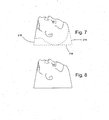
- the image data captured by the cameras 210a and 210b are processed and combined to form a single image data set, represented in Figure 7 .
- the image data set is processed and modified.
- the image of the patient captured by the cameras 210a and 210b will contain features that are undercut, such as the patient's ears, neck and the back of the head.
- the image processing removes the undercuts from the image data set.
- the image processing extends the image to a line 214 corresponding to the upper surface of the treatment table. In this way, the final restraint will extend to the treatment table, where it can be secured, to immobilize the patient, as will be described and shown hereinafter.
- the image data set is modified as shown in Figure 7 to have the draft necessary for the restraint to be properly formed.
- the draft is represented in Figure 7 by the lines 216 providing the overall image with a generally upwardly tapered form.
- a representation of the completed 3D image data set is shown in Figure 8 .
- the processing of the captured image data to generate the 3D image data set may be accomplished by a suitable processor using appropriate imaging software that form part of the imaging system.
- the raw image data may be dispatched to a remote processor for the 3D image data set to be prepared.
- the representation of the image shown in Figures 7 and 8 is a side elevation of the head of the patient.
- the method of the present invention provides a 3D image data set that includes features of all surfaces of the patient's head, such that a 3D replica may be formed.
- a replica of the head of the patient is prepared using the 3D image data set.
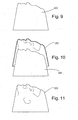
- the replica corresponding to the 3D image data set of Figure 8 is shown in cross-section in Figure 9 .
- the replica is used to form the medical restraint.
- This step is represented in Figure 10 , in which the replica 220 is shown in cross-section, with a vacuum-formed raw restraint 222, also shown in cross-section is being removed.
- the draft applied during the processing of the raw image data to prepare the 3D image data set is necessary to allow the raw restraint 222 to be easily released from the replica 220, as shown in Figure 10 .
- the raw restraint 222 is shown in side elevation in Figure 11 .
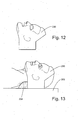
- a completed restraint 230 is shown in side elevation in Figure 12 .
- these features may be formed according to a set of standard procedures. Alternatively, they may be based upon data input by the clinician having reviewed the image data when prepared.
- the restraint 230 of Figure 12 is shown in position on the head of the patient. As will be noted, the patient is lying on the treatment table 202, with the neck rest 204 in place. The restraint 230 extends at the sides to the treatment table, where it is secured by suitable means, such as clamps or the like (not shown for clarity).
- an underlay bearing a full colour image of the relevant portion of the patient is prepared using the replica.
- an underlay 240 being vacuum formed on the replica 220 shown in Figure 9 .
- the underlay 240 is prepared from a sheet of plastic material onto which has been printed a colour image texture of the face of the patient. The sheet is then vacuum formed on the replica 220 to form a three-dimensional underlay.
- Figure 15 shows the underlay 240 in combination with the restraint 230 of Figure 12 . The features of the colour image on the underlay 240 are visible through the restraint 220, allowing the clinician to prepare for the treatment in advance of the patient arriving.
- the replica may be formed with a full colour image of the relevant portion of the patient on its surface.
- the replica 220 shown in Figures 9 and 10 may be formed with a full colour image of the face of the patient.
- the clinician is provided with the restraint, together with an accurate image of the patient to be treated, allowing the clinician to prepare for the treatment session in advance of the patient's arrival. This minimizes the length of time the patient is required to remain immobilized by the restraint.
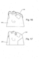
- a restraint 230 (represented in cross-section) being applied over a full colour replica 250.
- the surface of the replica 250 has been prepared with a colour image of the face of the patient.
- the full colour image is provided as a part of the 3D image data set produced during the imaging and image processing stage.
- the restraint 230 is shown in position on the coloured replica 250 in Figure 17 , which indicates how the clinician may use the replica and restraint to review the patient's treatment without the need to have the patient present and immobilized by the restraint.
- the clinician will often need to rely upon marks and indications to irradiate the patient accurately. These can be applied to the skin of the patient. However, they are more preferably incorporated into the restraint or the underlay of the present invention. Accordingly, the treatment marks may comprise part of the 3D image data set provided by the clinician as a result of the scanning steps of the present invention.
- a restraint 230 in cross-section
- the underlay bears a set of treatment marks 262 prepared to guide the clinician during the treatment of the patient.
- the treatment marks 262 on the underlay 260 are visible through the restraint 230.
- the underlay bearing the full colour image of the subject is of particular use in the finishing of the restraint or mask, as hereinbefore described.
- the use of the underlay allows the holes for the patient's eyes, nose and mouth to be accurately positioned and sized, leading to an accurate restraint that is both comfortable and practical for the patient to wear, while also immoblising the patient as required.
- the treatment marks are provided as part of the 3D image data set so as to appear on the surface of the replica.
- a replica 270 bearing a set of treatment marks 272 to provide an indication for the clinician during the treatment of the patient.
- the treatment marks have been incorporated into the replica following the data provided in the 3D image data set.
- the treatment marks 272 appear as a set of raised relief marks on the surface of the replica 270.
- a raw restraint 274 is being prepared using the replica 270, by the techniques described hereinbefore, such as vacuum forming.
- the raw restraint 274 prepared in this way is represented in Figure 21 and bears on its inner surface a set of treatment marks 276 present in the form of an impression relief.
- the completed restraint 278 is shown in Figure 22 bearing the set of treatment marks 276.
- the treatment marks provided on either the underlay or the replica and restraint form part of the 3D image data set produced as a result of the imaging and processing stages of the method of the present invention.
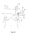
- the capture of the treatment marks is represented in Figure 23 , where a woman, generally indicated as 280, has been marked with a set of treatment marks 282 prior to treatment for breast cancer.
- An imaging system, generally indicated as 284, comprises a single projector 286 and a pair of digital cameras 288a and 288b.
- the projector 286 projects an array of lines onto the breast of the patient, represented by the grid 290. Images of the array as projected onto the breast of the patient are captured by both the cameras 288a and 288b, together with the set of treatment marks 282.
- the treatment marks 282 are thus incorporated into the raw image data set and are retained in the 3D image data set, from which the replica and underlay, if used, are prepared as described hereinbefore.
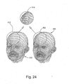
- FIG. 24 there is shown a representation of the method of the present invention applied to monitoring the course of treatment of a patient.
- a representation of the 3D image data set 300 obtained during an early stage in the treatment of a patient with a tumour in the frontal portion of the head.
- the 3D image data set 300 has been obtained as a 360 degree image data set using an imaging system of the type shown in Figure 4 and as described hereinbefore.
- the portion of the patient of interest is that lying within the circle 302 shown in Figure 24 positioned approximately at the forehead of the patient.
- the tumour was evidenced by virtue of a considerable swelling of the forehead of the patient.
- a second 3D image data set 310 was obtained in the same manner as before.
- the region of interest in the second 3D image data set is indicated by the circle 312 in Figure 24 .
- the method of the present invention comprises comparing the first and second 3D image data sets to determine any change in the shape and/or dimensions of the head of the patient. As represented in the circle 314 in Figure 24 , a comparison of the two image data sets shows that the treatment has successfully reduced the size of the tumour, as evidenced by the reduction in swelling and change in shape of the forehead of the patient.
- the imaging and image processing method of the present invention may be applied in the fitting of items and garments to a subject, in particular the fitting of medical compression hosiery to a patient.
- This method is represented in Figure 25 where there is shown the leg of a patient undergoing imaging.
- the leg of the patient generally indicated as 400, is imaged using an imaging system generally indicated as 410 and comprising three imaging sub-systems 412a, 412b and 412c in order to provide a 360 degree image data set.
- Each imaging sub-system comprises a projector 414a, 414b and 414c and a digital imaging camera 416a, 416b and 416c.
- the region of the leg 400 above and below the knee of the patient is being imaged to provide a 3D image data set of the region to be treated.
- the 3D image data set produced by the method and system represented by Figure 25 may be used in the manufacture of custom fit compression hosiery.
- the data set may be used in the selection of a compression hosiery to provide the required range of compression to treat the affected area.
- the 3D image data set may be compared with similar image data sets obtained at earlier stages in the treatment of the patient, in order to track and monitor the progress of the treatment. If the 3D image data set is to be used in the manufacture of a custom-fit compression hosiery or in the selection of the appropriate pre-existing hosiery item, the 3D image data may be reduced to a set of predetermined measurement criteria.
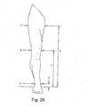
- Figure 26 a representation of a set of measurements to be derived from the 3D image data set and required to prepared or select the appropriate compression hosiery.
- the predetermined set of measurements comprise the girth A of the ankle of the patient at a distance X from the ground, the girth B of the knee of the patient at a distance Y from the ground, and the girth C of the thigh of the patient at a distance Z from the ground.
- Such a set of measurements may be used in the manufacture or fitting of compression hosiery.
- a database may be constructed of such measurements in order to track the progress of the treatment of the patient.
Landscapes
- Health & Medical Sciences (AREA)
- Engineering & Computer Science (AREA)
- Life Sciences & Earth Sciences (AREA)
- Physics & Mathematics (AREA)
- General Physics & Mathematics (AREA)
- Surgery (AREA)
- General Health & Medical Sciences (AREA)
- Computer Vision & Pattern Recognition (AREA)
- Medical Informatics (AREA)
- Nuclear Medicine, Radiotherapy & Molecular Imaging (AREA)
- Animal Behavior & Ethology (AREA)
- Public Health (AREA)
- Veterinary Medicine (AREA)
- Heart & Thoracic Surgery (AREA)
- Biomedical Technology (AREA)
- Neurosurgery (AREA)
- Oral & Maxillofacial Surgery (AREA)
- Pathology (AREA)
- Molecular Biology (AREA)
- Theoretical Computer Science (AREA)
- Materials Engineering (AREA)
- Chemical & Material Sciences (AREA)
- Manufacturing & Machinery (AREA)
- Quality & Reliability (AREA)
- Radiology & Medical Imaging (AREA)
- Nursing (AREA)
- Orthopedic Medicine & Surgery (AREA)
- Vascular Medicine (AREA)
- Biophysics (AREA)
- Otolaryngology (AREA)
- Measurement Of The Respiration, Hearing Ability, Form, And Blood Characteristics Of Living Organisms (AREA)
- Measuring And Recording Apparatus For Diagnosis (AREA)
- Radiation-Therapy Devices (AREA)
Claims (15)
- Verfahren zur Herstellung einer klinischen Haltevorrichtung (230) für ein Subjekt, wobei das Verfahren Folgendes beinhaltet:Erzeugen eines 3D-Bilddatensatzes, der durch Abtasten des festzuhaltenden Teils (2) des Subjekts erhalten wird, das vorzugsweise das Abtasten des festzuhaltenden Teils des Subjekts beinhaltet, um einen 3D-Bilddatensatz zu erzeugen;Erzeugen einer dreidimensionalen Nachbildung (220, 270) des Teils (2) des Subjekts von dem 3D-Bilddatensatz; undHerstellen einer klinischen Haltevorrichtung (230) mit Hilfe der dreidimensionalen Nachbildung (220, 270); dadurch gekennzeichnet, dassdie 3D-Bilddaten verarbeitet werden, um einen Teil der Gesamtheit des Bildes zu vergrößern, um einen Abstand zwischen dem Subjekt und der Haltevorrichtung zu erzeugen.
- Verfahren nach Anspruch 1, wobei der 3D-Bilddatensatz mit einem Verfahren hergestellt wird, das die folgenden Schritte beinhaltet:Beleuchten des Teils (2) des Subjekts mit einem Lichtmuster mit mehreren Lichtebenen, wobei die Wellenlänge des Lichtmusters räumlich über den Teil des Subjekts variiert und wobei die genannte wenigstens eine Lichtebene wenigstens einem Winkel entspricht, bei dem Licht dieser Wellenlänge emittiert wird, und nur eine einzige Spektralkomponente enthält, wobei das Lichtmuster bei dem Beleuchtungsschritt vorzugsweise über das sichtbare Lichtspektrum, das infrarote Lichtspektrum oder das ultraviolette Lichtspektrum variiert wird;Erfassen eines Bildes des Teils (2) des so beleuchteten Subjekts mit einer Kamera (8, 288); undBerechnen eines Abstands zu einem Punkt auf dem genannten Objekt oder in der genannten Szene mittels Triangulation auf der Basis eines Grundlinienabstands zwischen der genannten Lichtquelle und der Kamera (8, 288), eines Winkels zwischen der Kamera (8, 288) und der Grundlinie und eines Winkels, bei dem auf den Punkt fallendes Licht von der Lichtquelle emittiert wird, ermittelt anhand von Rot/Grün/Blau-Werten, die der Wellenlänge des auf den Punkt fallenden Lichts entsprechen.
- Verfahren nach Anspruch 1 oder 2, wobei der 3D-Bilddatensatz mit einem Verfahren hergestellt wird, das die folgenden Schritte beinhaltet:Projizieren eines vorbestimmten Musters (10) von Komponenten, wobei das Muster von Komponenten vorzugsweise mehrere Linien, bevorzugter ein Gitter von geraden Linien beinhaltet, auf den Teil (2) des Subjekts, wobei die Komponenten eine bekannte relative Positionierung haben;Erfassen eines Bildes des Teils (2) des Subjekts; undBerechnen der dreidimensionalen Form auf der Basis von relativen Abständen zwischen Musterkomponenten wie in dem erfassten Bild beobachtet.
- Verfahren nach Anspruch 3, wobei absolute Abmessungen der Form oder des Bildes durch Festlegen eines geeigneten Skalenfaktors erhalten werden.
- Verfahren nach Anspruch 3 oder 4, wobei relative räumliche Positionen von Punkten auf dem Teil (2) des Subjekts direkt anhand von relativen beobachteten Punkten der Komponenten des Bildes berechnet werden.
- Verfahren nach einem der Ansprüche 3 bis 5, wobei das Abbildungssystem durch Präsentieren von zwei Ebenen kalibriert wird, die einen bekannten Winkel bilden.
- Verfahren nach einem vorherigen Anspruch, wobei in dem Abtastschritt mehrere verschiedene Rohbilder von dem ganzen oder einem Teil des Teil(s) (2) des Subjekts erfasst werden, wobei die Rohbilder zu dem 3D-Bilddatensatz kombiniert werden.
- Verfahren nach einem vorherigen Anspruch, wobei der 3D-Bilddatensatz vor der Verwendung bei der Herstellung der Nachbildung (220, 270) modifiziert wird, wobei der 3D-Bilddatensatz vorzugsweise durch eines oder mehrere der Folgenden modifiziert wird:Interpolation zum Ergänzen fehlender Bilddaten;Entfernen von hinterschnittenen Teilen der Bilddaten;Versehen des Bildes mit einer geeigneten Konizität oder Schrägung zum Formen;Erweitern des Bildes, um eine Region zum Anbringen an einer Behandlungsplattform (202) oder dergleichen zu erzeugen; oderVorsehen von einem oder mehreren Löchern in dem Bild.
- Verfahren nach einem vorherigen Anspruch, wobei der 3D-Bilddatensatz ein Vollfarbbild des Teils (2) des Subjekts beinhaltet.
- Verfahren nach einem vorherigen Anspruch, wobei die Nachbildung (220, 270) mit Indikationen (272) auf ihrer Oberfläche zur Verwendung beim Lenken des klinischen Verfahrens versehen wird, wobei die auf der Nachbildung (220, 270) ausgebildeten Indikationen (272) vorzugsweise von Indikationen abgeleitet werden, die auf der Oberfläche des Teils (2) des Subjekts platziert und während des Abbildungsschrittes in dem Bild erfasst werden.
- Verfahren nach Anspruch 10, das ferner den Schritt des Ausbildens von Indikationen (276) auf der Haltevorrichtung (230) beinhaltet, entsprechend den auf der Oberfläche der Nachbildung (220, 270) ausgebildeten Indikationen (272), wobei die Indikationen (272) vorzugsweise als erhabene Teile der Oberfläche der Nachbildung (220, 270) ausgebildet sind, so dass entsprechende Eindrücke auf der Innenfläche der klinischen Haltevorrichtung (230) direkt während des Schrittes des Ausbildens der Nachbildung (220, 270) ausgebildet werden.
- Verfahren nach einem vorherigen Anspruch, wobei die Nachbildung (220, 270) mit einem Vollfarbbild des Teils (2) des Subjekts auf seiner Oberfläche versehen wird.
- Verfahren nach einem vorherigen Anspruch, das ferner den Schritt des Herstellens einer flexiblen Schicht (240) von der Nachbildung (220, 270) beinhaltet, wobei die flexible Schicht (240) vorzugsweise mit Indikationen (272) des Gebrauchs bei der Herstellung der Haltevorrichtung und/oder beim Lenken des medizinischen Verfahrens versehen wird, wobei die flexible Schicht (240) bevorzugter als ein Bild auf einer flachen Folie von den 3D-Bilddaten ausgebildet wird, wobei die flache Folie mittels Unterdruck um die Oberfläche der Nachbildung geformt wird.
- Verfahren nach einem vorherigen Anspruch, wobei die Nachbildung (220, 270) in Form einer Anordnung von longitudinalen beweglichen Stiften hergestellt wird, wobei die Verschiebung jedes Stifts von einem Bezugspunkt anhand der 3D-Bilddaten ermittelt wird, so dass die Oberfläche der Nachbildung (220, 270) von den Enden der mehreren Stifte gebildet wird.
- Verfahren nach einem vorherigen Anspruch, wobei die Haltevorrichtung (230) transparent ist, wobei die Haltevorrichtung vorzugsweise in der Region des Teils (2) des Subjekts transparent ist, der klinischer Aufmerksamkeit bedarf.
Applications Claiming Priority (2)
| Application Number | Priority Date | Filing Date | Title |
|---|---|---|---|
| GB0601801A GB2434541B (en) | 2006-01-30 | 2006-01-30 | Method of preparing a medical restraint |
| PCT/GB2007/000303 WO2007085864A2 (en) | 2006-01-30 | 2007-01-30 | Method of preparing a medical restraint |
Publications (2)
| Publication Number | Publication Date |
|---|---|
| EP1996107A2 EP1996107A2 (de) | 2008-12-03 |
| EP1996107B1 true EP1996107B1 (de) | 2014-08-06 |
Family
ID=36061094
Family Applications (1)
| Application Number | Title | Priority Date | Filing Date |
|---|---|---|---|
| EP07705069.8A Not-in-force EP1996107B1 (de) | 2006-01-30 | 2007-01-30 | Verfahren zur herstellung einer medizinischen fixierung |
Country Status (5)
| Country | Link |
|---|---|
| US (1) | US8320648B2 (de) |
| EP (1) | EP1996107B1 (de) |
| CA (1) | CA2640379A1 (de) |
| GB (2) | GB2455926B (de) |
| WO (1) | WO2007085864A2 (de) |
Cited By (1)
| Publication number | Priority date | Publication date | Assignee | Title |
|---|---|---|---|---|
| EP3867597A4 (de) * | 2018-10-18 | 2022-06-22 | Cyberoptics Corporation | Dreidimensionaler sensor mit entgegengesetzten kanälen |
Families Citing this family (53)
| Publication number | Priority date | Publication date | Assignee | Title |
|---|---|---|---|---|
| US20080027974A1 (en) * | 2006-07-24 | 2008-01-31 | Collins Donald W | Intensity modulated radiation therapy filtration apparatus, system and method |
| CN101821579B (zh) | 2007-08-17 | 2013-01-23 | 瑞尼斯豪公司 | 相位分析测量装置和方法 |
| US9572402B2 (en) * | 2007-10-23 | 2017-02-21 | Nike, Inc. | Articles and methods of manufacturing articles |
| US9788603B2 (en) | 2007-10-23 | 2017-10-17 | Nike, Inc. | Articles and methods of manufacture of articles |
| US9795181B2 (en) | 2007-10-23 | 2017-10-24 | Nike, Inc. | Articles and methods of manufacture of articles |
| US8217993B2 (en) * | 2009-03-20 | 2012-07-10 | Cranial Technologies, Inc. | Three-dimensional image capture system for subjects |
| US8103088B2 (en) * | 2009-03-20 | 2012-01-24 | Cranial Technologies, Inc. | Three-dimensional image capture system |
| GB0915904D0 (en) | 2009-09-11 | 2009-10-14 | Renishaw Plc | Non-contact object inspection |
| US20110172526A1 (en) * | 2010-01-12 | 2011-07-14 | Martin Lachaine | Feature Tracking Using Ultrasound |
| US8861800B2 (en) * | 2010-07-19 | 2014-10-14 | Carnegie Mellon University | Rapid 3D face reconstruction from a 2D image and methods using such rapid 3D face reconstruction |
| US8579620B2 (en) * | 2011-03-02 | 2013-11-12 | Andy Wu | Single-action three-dimensional model printing methods |
| US8477903B2 (en) | 2011-03-31 | 2013-07-02 | Axellis Ventures Ltd | Validating a compensator for use in a radiation therapy machine to treat a cancer patient |
| DE102011055295A1 (de) * | 2011-11-11 | 2013-05-16 | Nordli Gard Consulting & Research | Verfahren zum Reproduzieren einer Form eines Oberflächenbereichs eines Körpers eines Lebewesens |
| EP2626008A1 (de) * | 2012-02-10 | 2013-08-14 | Teamolmed Syd AB | Vorrichtung zur Fixierung eines Körperteils und Verfahren dafür |
| EP2875325B1 (de) * | 2012-07-19 | 2019-11-13 | 3M Innovative Properties Company | Bestimmung der dehnung einer elastischen bandage |
| CN102920513B (zh) * | 2012-11-13 | 2014-10-29 | 吉林大学 | 一种基于投影仪的增强现实系统试验平台 |
| US8966681B2 (en) | 2013-02-26 | 2015-03-03 | Linda L. Burch | Exercise mat |
| US9320316B2 (en) | 2013-03-14 | 2016-04-26 | Under Armour, Inc. | 3D zonal compression shoe |
| GB201306109D0 (en) * | 2013-04-04 | 2013-05-22 | Zaybu Ltd | Image capture apparatus and method |
| GB2520255A (en) * | 2013-11-12 | 2015-05-20 | Asda Stores Ltd | Method and apparatus for 3D Printing |
| US11718035B2 (en) | 2014-02-07 | 2023-08-08 | Printer Tailored, Llc | Customized, wearable 3D printed articles and methods of manufacturing same |
| US20170027477A1 (en) * | 2014-04-09 | 2017-02-02 | Bayer Healthcare Llc | Method, apparatus, and computer-readable medium for generating a set of recommended orthotic products |
| BE1022172B9 (nl) | 2014-12-31 | 2017-12-15 | Orfit Ind Nv | Werkwijze voor het vervaardigen van een immobilisatie masker |
| WO2016131021A1 (en) * | 2015-02-12 | 2016-08-18 | Glowforge Inc. | Safety and reliability guarantees for laser fabrication |
| US10039343B2 (en) | 2015-05-08 | 2018-08-07 | Under Armour, Inc. | Footwear including sole assembly |
| US10010134B2 (en) | 2015-05-08 | 2018-07-03 | Under Armour, Inc. | Footwear with lattice midsole and compression insert |
| US10010133B2 (en) | 2015-05-08 | 2018-07-03 | Under Armour, Inc. | Midsole lattice with hollow tubes for footwear |
| DE102015113807A1 (de) * | 2015-08-20 | 2017-02-23 | Fischerwerke Gmbh & Co. Kg | System und Verfahren zur Erstellung einer Befestigungsanordnung, sowie derart erstellte Befestigungsanordnung |
| GB201515877D0 (en) | 2015-09-08 | 2015-10-21 | Technology In Motion Ltd And Ing Corp Spol S R O | Cranial remoulding orthosis and method of manufacture thereof |
| US10406800B2 (en) * | 2015-11-03 | 2019-09-10 | Caterpillar Inc. | Machine control system for contour crafting |
| US10220172B2 (en) * | 2015-11-25 | 2019-03-05 | Resmed Limited | Methods and systems for providing interface components for respiratory therapy |
| US10392864B2 (en) | 2016-01-21 | 2019-08-27 | Baker Hughes, A Ge Company, Llc | Additive manufacturing controlled failure structure and method of making same |
| US10299722B1 (en) * | 2016-02-03 | 2019-05-28 | Bao Tran | Systems and methods for mass customization |
| JP6662449B2 (ja) * | 2016-03-09 | 2020-03-11 | 株式会社ニコン | 検出装置、検出システム、検出方法、及び検出プログラム |
| JP2017161370A (ja) * | 2016-03-09 | 2017-09-14 | 株式会社ニコン | 検出装置、検出システム、検出方法、及び検出プログラム |
| JP6620275B2 (ja) * | 2016-03-22 | 2019-12-18 | 株式会社イノベーションゲート | 体表面固定具作成支援装置、体表面固定具作成支援方法、及び体表面固定具作成支援プログラム |
| US10293565B1 (en) * | 2016-04-12 | 2019-05-21 | Bao Tran | Systems and methods for mass customization |
| US9789338B1 (en) | 2016-04-13 | 2017-10-17 | Vision Rt Ltd. | Patient monitoring system |
| WO2017190780A1 (en) * | 2016-05-04 | 2017-11-09 | Brainlab Ag | Patient pre-positioning in frameless cranial radiosurgery using thermal imaging |
| US10251438B2 (en) | 2016-08-10 | 2019-04-09 | Lymphatech | Methods of generating compression garment measurement information for a patient body part and fitting pre-fabricated compression garments thereto |
| US10045581B2 (en) | 2016-08-10 | 2018-08-14 | Michael J. Weiler | Methods of generating compression garment measurement information for a patient body part or body area of interest and use thereof |
| US11364675B2 (en) | 2016-11-01 | 2022-06-21 | Medtec Llc | Printing method for thermoplastic retention device preform |
| US10842242B2 (en) * | 2016-12-22 | 2020-11-24 | Johnson & Johnson Consumer Inc. | System for targeted application of topical agents to an isolated body part |
| US10710356B2 (en) | 2017-03-30 | 2020-07-14 | Cranial Technologies, Inc. | Apparatus for point of service manufacture of custom cranial remodeling devices |
| US10682846B2 (en) * | 2017-03-30 | 2020-06-16 | Cranial Technologies, Inc. | Point of service manufacturing method for custom cranial remodeling device |
| US10779614B2 (en) | 2017-06-21 | 2020-09-22 | Under Armour, Inc. | Cushioning for a sole structure of performance footwear |
| US11407034B2 (en) | 2017-07-06 | 2022-08-09 | OmniTek Technology Ltda. | Selective laser melting system and method of using same |
| EP3833424A1 (de) * | 2018-08-07 | 2021-06-16 | The Procter & Gamble Company | Verfahren zur bewertung und visualisierung des sitzes eines applikators |
| WO2020099510A2 (en) * | 2018-11-14 | 2020-05-22 | Hôpitaux Universitaires de Genève | Medical device for radiotherapy and method of manufacturing the same |
| US10977775B2 (en) * | 2018-12-07 | 2021-04-13 | Himax Technologies Limited | Depth decoding system and method for ground truth image rectification |
| US20200275862A1 (en) * | 2019-03-01 | 2020-09-03 | Wiivv Wearables Inc. | Multiple physical conditions embodied in body part images to generate an orthotic |
| US10842680B1 (en) | 2019-08-31 | 2020-11-24 | Michael J. Weiler | Methods and systems for fitting compression garments from digital imagery |
| US11579119B1 (en) | 2019-11-22 | 2023-02-14 | Cypress In-Line Inspection, LLC | Radial springs on sensor arms of pipeline inspection tool |
Family Cites Families (32)
| Publication number | Priority date | Publication date | Assignee | Title |
|---|---|---|---|---|
| DE3340482C2 (de) * | 1983-11-09 | 1986-04-24 | Fritsch Orthopädie-Technik Inh. Norbert Fritsch, 8501 Fürth | Verfahren zur Herstellung einer durchsichtigen und strahlendurchlässigen Maske zum Anbringen von für die punktgenaue Bestrahlung von menschlichen Körperteilen notwendigen Markierungen |
| DE4102258A1 (de) | 1991-01-23 | 1992-07-30 | Artos Med Produkte | Verfahren zur herstellung einer negativform |
| DE69327661T2 (de) * | 1992-11-09 | 2000-07-20 | Ormco Corp., Glendora | Verfahren und vorrichtung zum herstellen von individuell angepasstenorthodontischen einrichtungen |
| US5741215A (en) * | 1993-09-10 | 1998-04-21 | The University Of Queensland | Stereolithographic anatomical modelling process |
| US5432704A (en) * | 1993-11-23 | 1995-07-11 | Clemson University | Adaptive lamina generation for shape dependent process control and/or object decomposition |
| US5926388A (en) * | 1994-12-09 | 1999-07-20 | Kimbrough; Thomas C. | System and method for producing a three dimensional relief |
| US5596504A (en) * | 1995-04-10 | 1997-01-21 | Clemson University | Apparatus and method for layered modeling of intended objects represented in STL format and adaptive slicing thereof |
| US6317617B1 (en) * | 1997-07-25 | 2001-11-13 | Arch Development Corporation | Method, computer program product, and system for the automated analysis of lesions in magnetic resonance, mammogram and ultrasound images |
| US6363163B1 (en) * | 1998-02-23 | 2002-03-26 | Arch Development Corporation | Method and system for the automated temporal subtraction of medical images |
| US6636310B1 (en) * | 1998-05-12 | 2003-10-21 | Metroptic Technologies, Ltd. | Wavelength-dependent surface contour measurement system and method |
| US6356263B2 (en) | 1999-01-27 | 2002-03-12 | Viewpoint Corporation | Adaptive subdivision of mesh models |
| DE19940895A1 (de) * | 1999-08-27 | 2001-04-19 | Inst Neurosimultion Und Bildte | Verfahren und Einrichtung zur Klassifizierung von Hautanomalien, insbesondere von Melanomen und melanomähnlichen Erscheinungen |
| GB2358752A (en) * | 2000-01-31 | 2001-08-01 | Tricorder Technology Plc | Surface or volumetric data processing method and apparatus |
| WO2001078005A2 (en) * | 2000-04-11 | 2001-10-18 | Cornell Research Foundation, Inc. | System and method for three-dimensional image rendering and analysis |
| US6564086B2 (en) * | 2000-05-03 | 2003-05-13 | Rocky Mountain Biosystems, Inc. | Prosthesis and method of making |
| US6748400B2 (en) * | 2000-06-22 | 2004-06-08 | David F. Quick | Data access system and method |
| US6909792B1 (en) * | 2000-06-23 | 2005-06-21 | Litton Systems, Inc. | Historical comparison of breast tissue by image processing |
| US6983063B1 (en) * | 2000-06-29 | 2006-01-03 | Siemens Corporate Research, Inc. | Computer-aided diagnosis method for aiding diagnosis of three dimensional digital image data |
| AU2002214869A1 (en) * | 2000-10-31 | 2002-05-15 | Centre National De La Recherche Scientifique (C.N.R.S.) | High precision modeling of a body part using a 3d imaging system |
| US6909794B2 (en) * | 2000-11-22 | 2005-06-21 | R2 Technology, Inc. | Automated registration of 3-D medical scans of similar anatomical structures |
| GB2371964A (en) * | 2001-01-31 | 2002-08-07 | Tct Internat Plc | Surface imaging for patient positioning in radiotherapy |
| US20040147830A1 (en) * | 2003-01-29 | 2004-07-29 | Virtualscopics | Method and system for use of biomarkers in diagnostic imaging |
| WO2004084034A2 (en) * | 2003-03-17 | 2004-09-30 | Lux Cindy M | Patient registration kiosk |
| US7492931B2 (en) * | 2003-11-26 | 2009-02-17 | Ge Medical Systems Global Technology Company, Llc | Image temporal change detection and display method and apparatus |
| US6980871B1 (en) * | 2004-07-16 | 2005-12-27 | .Decimal, Inc. | Method for providing a radiation filter for a radiation treatment machine |
| US20070033786A1 (en) * | 2005-08-09 | 2007-02-15 | Bradley George A | Milling machine turning systems and methods |
| US8929621B2 (en) * | 2005-12-20 | 2015-01-06 | Elekta, Ltd. | Methods and systems for segmentation and surface matching |
| CA2642615A1 (en) * | 2006-02-15 | 2007-08-30 | Otismed Corp | Arthroplasty jigs and related methods |
| US20080027974A1 (en) * | 2006-07-24 | 2008-01-31 | Collins Donald W | Intensity modulated radiation therapy filtration apparatus, system and method |
| EP2108401A1 (de) | 2008-04-11 | 2009-10-14 | Ion Beam Applications S.A. | Kompensierungsvorrichtung und Verfahren der Organbewegung |
| US8208601B2 (en) | 2008-08-13 | 2012-06-26 | Oncology Tech Llc | Integrated shaping and sculpting unit for use with intensity modulated radiation therapy (IMRT) treatment |
| JP5799015B2 (ja) | 2009-08-31 | 2015-10-21 | コーニンクレッカ フィリップス エヌ ヴェ | 放射線治療計画に使用される補償器のための対話型のコンピュータを利用したエディタ |
-
2006
- 2006-01-30 GB GB0904207A patent/GB2455926B/en not_active Expired - Fee Related
- 2006-01-30 GB GB0601801A patent/GB2434541B/en not_active Expired - Fee Related
-
2007
- 2007-01-30 CA CA002640379A patent/CA2640379A1/en not_active Abandoned
- 2007-01-30 US US12/162,573 patent/US8320648B2/en not_active Expired - Fee Related
- 2007-01-30 WO PCT/GB2007/000303 patent/WO2007085864A2/en not_active Ceased
- 2007-01-30 EP EP07705069.8A patent/EP1996107B1/de not_active Not-in-force
Cited By (3)
| Publication number | Priority date | Publication date | Assignee | Title |
|---|---|---|---|---|
| EP3867597A4 (de) * | 2018-10-18 | 2022-06-22 | Cyberoptics Corporation | Dreidimensionaler sensor mit entgegengesetzten kanälen |
| EP3867596A4 (de) * | 2018-10-18 | 2022-11-16 | Cyberoptics Corporation | Dreidimensionaler sensor mit entgegengesetzten kanälen |
| EP4235573A3 (de) * | 2018-10-18 | 2023-10-04 | Cyberoptics Corporation | Dreidimensionaler sensor mit entgegengesetzten kanälen |
Also Published As
| Publication number | Publication date |
|---|---|
| US8320648B2 (en) | 2012-11-27 |
| GB2434541B (en) | 2009-06-17 |
| GB2455926A (en) | 2009-07-01 |
| EP1996107A2 (de) | 2008-12-03 |
| WO2007085864A3 (en) | 2007-10-25 |
| CA2640379A1 (en) | 2007-08-02 |
| GB2434541A (en) | 2007-08-01 |
| GB0904207D0 (en) | 2009-04-22 |
| GB2455926B (en) | 2010-09-01 |
| GB0601801D0 (en) | 2006-03-08 |
| WO2007085864A2 (en) | 2007-08-02 |
| US20090316965A1 (en) | 2009-12-24 |
Similar Documents
| Publication | Publication Date | Title |
|---|---|---|
| EP1996107B1 (de) | Verfahren zur herstellung einer medizinischen fixierung | |
| Feng et al. | Computer-assisted technique for the design and manufacture of realistic facial prostheses | |
| Cheah et al. | Integration of laser surface digitizing with CAD/CAM techniques for developing facial prostheses. Part 1: Design and fabrication of prosthesis replicas. | |
| Coward et al. | Fabrication of a wax ear by rapid-process modeling using stereolithography. | |
| KR101726013B1 (ko) | 의족 또는 보조기용 교체 가능한 페어링 | |
| EP2273923B1 (de) | Verfahren zur ableitung anatomischer und/oder pathologischer strukturen aus über bildgebungstechnologien gewonnenen daten | |
| JP2001170080A (ja) | インプラントのための穿孔補助手段を製造するための方法 | |
| US11173051B2 (en) | Apparatus and methods for three dimensional plasthesis prostheses | |
| KR20180040664A (ko) | 치료 지원 시스템 및 이의 작동 방법, 및 치료 지원 프로그램을 기억하는 기억 매체 | |
| Fisher et al. | Evaluation of 3-D printed immobilisation shells for head and neck IMRT | |
| Denour et al. | The use of three-dimensional photography and printing in the fabrication of a nasal prosthesis | |
| Jablonski et al. | Accuracy of capturing oncology facial defects with multimodal image fusion versus laser scanning | |
| KR20190005016A (ko) | 맞춤형 두상 교정모 가공 방법 | |
| CN118718270A (zh) | 用于施加辐射的模型、用于制作所述模型的方法以及所述模型的用途 | |
| Tahmawy et al. | A novel technique for CAD‐CAM assisted digital ocular prosthesis | |
| Kovacs et al. | Computer aided surgical reconstruction after complex facial burn injuries–opportunities and limitations | |
| Batra et al. | 3-Dimensional Evaluation of Two PNAM Techniques (Modified Grayson & AlignerNAM) on Facial Soft Tissue Morphology: A Randomised Clinical Trial. | |
| Jamayet et al. | New approach to 3D printing of facial prostheses using combination of open source software and conventional techniques: a case report | |
| Sharma et al. | Reverse engineering and CAD/CAM application in the design of maxillofacial prosthesis | |
| WO2023249977A1 (en) | 3d subtractive manufacturing of casts, braces, splints and other orthoses | |
| Willis et al. | An automated design pipeline for transparent facial orthoses: A clinical study | |
| KR102156592B1 (ko) | 방사선 치료용 마스크 제작방법 | |
| CN119185815B (zh) | 一种基于舌癌患者三维影像数据及3d打印技术制作放疗用口腔支架的方法 | |
| Sun et al. | The application of full scale 3D anthropometric digital model system in radiotherapy positioning and verification | |
| EP3833308A1 (de) | Herstellung einer massgeschneiderten medizinischen schiene oder klammer zur immobilisierung eines ausgewählten bereichs eines körperteils eines patienten |
Legal Events
| Date | Code | Title | Description |
|---|---|---|---|
| PUAI | Public reference made under article 153(3) epc to a published international application that has entered the european phase |
Free format text: ORIGINAL CODE: 0009012 |
|
| 17P | Request for examination filed |
Effective date: 20080801 |
|
| AK | Designated contracting states |
Kind code of ref document: A2 Designated state(s): AT BE BG CH CY CZ DE DK EE ES FI FR GB GR HU IE IS IT LI LT LU LV MC NL PL PT RO SE SI SK TR |
|
| DAX | Request for extension of the european patent (deleted) | ||
| 17Q | First examination report despatched |
Effective date: 20130130 |
|
| GRAP | Despatch of communication of intention to grant a patent |
Free format text: ORIGINAL CODE: EPIDOSNIGR1 |
|
| INTG | Intention to grant announced |
Effective date: 20140226 |
|
| GRAS | Grant fee paid |
Free format text: ORIGINAL CODE: EPIDOSNIGR3 |
|
| GRAA | (expected) grant |
Free format text: ORIGINAL CODE: 0009210 |
|
| AK | Designated contracting states |
Kind code of ref document: B1 Designated state(s): AT BE BG CH CY CZ DE DK EE ES FI FR GB GR HU IE IS IT LI LT LU LV MC NL PL PT RO SE SI SK TR |
|
| REG | Reference to a national code |
Ref country code: GB Ref legal event code: FG4D |
|
| REG | Reference to a national code |
Ref country code: CH Ref legal event code: EP Ref country code: AT Ref legal event code: REF Ref document number: 680615 Country of ref document: AT Kind code of ref document: T Effective date: 20140815 |
|
| REG | Reference to a national code |
Ref country code: IE Ref legal event code: FG4D |
|
| REG | Reference to a national code |
Ref country code: DE Ref legal event code: R096 Ref document number: 602007037965 Country of ref document: DE Effective date: 20140911 |
|
| REG | Reference to a national code |
Ref country code: AT Ref legal event code: MK05 Ref document number: 680615 Country of ref document: AT Kind code of ref document: T Effective date: 20140806 |
|
| REG | Reference to a national code |
Ref country code: NL Ref legal event code: VDEP Effective date: 20140806 |
|
| REG | Reference to a national code |
Ref country code: LT Ref legal event code: MG4D |
|
| PG25 | Lapsed in a contracting state [announced via postgrant information from national office to epo] |
Ref country code: GR Free format text: LAPSE BECAUSE OF FAILURE TO SUBMIT A TRANSLATION OF THE DESCRIPTION OR TO PAY THE FEE WITHIN THE PRESCRIBED TIME-LIMIT Effective date: 20141107 Ref country code: FI Free format text: LAPSE BECAUSE OF FAILURE TO SUBMIT A TRANSLATION OF THE DESCRIPTION OR TO PAY THE FEE WITHIN THE PRESCRIBED TIME-LIMIT Effective date: 20140806 Ref country code: ES Free format text: LAPSE BECAUSE OF FAILURE TO SUBMIT A TRANSLATION OF THE DESCRIPTION OR TO PAY THE FEE WITHIN THE PRESCRIBED TIME-LIMIT Effective date: 20140806 Ref country code: LT Free format text: LAPSE BECAUSE OF FAILURE TO SUBMIT A TRANSLATION OF THE DESCRIPTION OR TO PAY THE FEE WITHIN THE PRESCRIBED TIME-LIMIT Effective date: 20140806 Ref country code: PT Free format text: LAPSE BECAUSE OF FAILURE TO SUBMIT A TRANSLATION OF THE DESCRIPTION OR TO PAY THE FEE WITHIN THE PRESCRIBED TIME-LIMIT Effective date: 20141209 Ref country code: SE Free format text: LAPSE BECAUSE OF FAILURE TO SUBMIT A TRANSLATION OF THE DESCRIPTION OR TO PAY THE FEE WITHIN THE PRESCRIBED TIME-LIMIT Effective date: 20140806 Ref country code: BG Free format text: LAPSE BECAUSE OF FAILURE TO SUBMIT A TRANSLATION OF THE DESCRIPTION OR TO PAY THE FEE WITHIN THE PRESCRIBED TIME-LIMIT Effective date: 20141106 |
|
| PG25 | Lapsed in a contracting state [announced via postgrant information from national office to epo] |
Ref country code: PL Free format text: LAPSE BECAUSE OF FAILURE TO SUBMIT A TRANSLATION OF THE DESCRIPTION OR TO PAY THE FEE WITHIN THE PRESCRIBED TIME-LIMIT Effective date: 20140806 Ref country code: NL Free format text: LAPSE BECAUSE OF FAILURE TO SUBMIT A TRANSLATION OF THE DESCRIPTION OR TO PAY THE FEE WITHIN THE PRESCRIBED TIME-LIMIT Effective date: 20140806 Ref country code: AT Free format text: LAPSE BECAUSE OF FAILURE TO SUBMIT A TRANSLATION OF THE DESCRIPTION OR TO PAY THE FEE WITHIN THE PRESCRIBED TIME-LIMIT Effective date: 20140806 Ref country code: IS Free format text: LAPSE BECAUSE OF FAILURE TO SUBMIT A TRANSLATION OF THE DESCRIPTION OR TO PAY THE FEE WITHIN THE PRESCRIBED TIME-LIMIT Effective date: 20141206 Ref country code: CY Free format text: LAPSE BECAUSE OF FAILURE TO SUBMIT A TRANSLATION OF THE DESCRIPTION OR TO PAY THE FEE WITHIN THE PRESCRIBED TIME-LIMIT Effective date: 20140806 Ref country code: LV Free format text: LAPSE BECAUSE OF FAILURE TO SUBMIT A TRANSLATION OF THE DESCRIPTION OR TO PAY THE FEE WITHIN THE PRESCRIBED TIME-LIMIT Effective date: 20140806 |
|
| PG25 | Lapsed in a contracting state [announced via postgrant information from national office to epo] |
Ref country code: CZ Free format text: LAPSE BECAUSE OF FAILURE TO SUBMIT A TRANSLATION OF THE DESCRIPTION OR TO PAY THE FEE WITHIN THE PRESCRIBED TIME-LIMIT Effective date: 20140806 Ref country code: EE Free format text: LAPSE BECAUSE OF FAILURE TO SUBMIT A TRANSLATION OF THE DESCRIPTION OR TO PAY THE FEE WITHIN THE PRESCRIBED TIME-LIMIT Effective date: 20140806 Ref country code: RO Free format text: LAPSE BECAUSE OF FAILURE TO SUBMIT A TRANSLATION OF THE DESCRIPTION OR TO PAY THE FEE WITHIN THE PRESCRIBED TIME-LIMIT Effective date: 20140806 Ref country code: SK Free format text: LAPSE BECAUSE OF FAILURE TO SUBMIT A TRANSLATION OF THE DESCRIPTION OR TO PAY THE FEE WITHIN THE PRESCRIBED TIME-LIMIT Effective date: 20140806 Ref country code: IT Free format text: LAPSE BECAUSE OF FAILURE TO SUBMIT A TRANSLATION OF THE DESCRIPTION OR TO PAY THE FEE WITHIN THE PRESCRIBED TIME-LIMIT Effective date: 20140806 Ref country code: DK Free format text: LAPSE BECAUSE OF FAILURE TO SUBMIT A TRANSLATION OF THE DESCRIPTION OR TO PAY THE FEE WITHIN THE PRESCRIBED TIME-LIMIT Effective date: 20140806 |
|
| REG | Reference to a national code |
Ref country code: DE Ref legal event code: R097 Ref document number: 602007037965 Country of ref document: DE |
|
| PLBE | No opposition filed within time limit |
Free format text: ORIGINAL CODE: 0009261 |
|
| STAA | Information on the status of an ep patent application or granted ep patent |
Free format text: STATUS: NO OPPOSITION FILED WITHIN TIME LIMIT |
|
| PG25 | Lapsed in a contracting state [announced via postgrant information from national office to epo] |
Ref country code: BE Free format text: LAPSE BECAUSE OF NON-PAYMENT OF DUE FEES Effective date: 20150131 |
|
| 26N | No opposition filed |
Effective date: 20150507 |
|
| REG | Reference to a national code |
Ref country code: CH Ref legal event code: PL |
|
| PG25 | Lapsed in a contracting state [announced via postgrant information from national office to epo] |
Ref country code: LU Free format text: LAPSE BECAUSE OF FAILURE TO SUBMIT A TRANSLATION OF THE DESCRIPTION OR TO PAY THE FEE WITHIN THE PRESCRIBED TIME-LIMIT Effective date: 20150130 |
|
| PG25 | Lapsed in a contracting state [announced via postgrant information from national office to epo] |
Ref country code: MC Free format text: LAPSE BECAUSE OF FAILURE TO SUBMIT A TRANSLATION OF THE DESCRIPTION OR TO PAY THE FEE WITHIN THE PRESCRIBED TIME-LIMIT Effective date: 20140806 |
|
| PG25 | Lapsed in a contracting state [announced via postgrant information from national office to epo] |
Ref country code: LI Free format text: LAPSE BECAUSE OF NON-PAYMENT OF DUE FEES Effective date: 20150131 Ref country code: CH Free format text: LAPSE BECAUSE OF NON-PAYMENT OF DUE FEES Effective date: 20150131 |
|
| REG | Reference to a national code |
Ref country code: IE Ref legal event code: MM4A |
|
| PG25 | Lapsed in a contracting state [announced via postgrant information from national office to epo] |
Ref country code: SI Free format text: LAPSE BECAUSE OF FAILURE TO SUBMIT A TRANSLATION OF THE DESCRIPTION OR TO PAY THE FEE WITHIN THE PRESCRIBED TIME-LIMIT Effective date: 20140806 |
|
| PG25 | Lapsed in a contracting state [announced via postgrant information from national office to epo] |
Ref country code: IE Free format text: LAPSE BECAUSE OF NON-PAYMENT OF DUE FEES Effective date: 20150130 |
|
| REG | Reference to a national code |
Ref country code: FR Ref legal event code: PLFP Year of fee payment: 10 |
|
| PG25 | Lapsed in a contracting state [announced via postgrant information from national office to epo] |
Ref country code: BE Free format text: LAPSE BECAUSE OF FAILURE TO SUBMIT A TRANSLATION OF THE DESCRIPTION OR TO PAY THE FEE WITHIN THE PRESCRIBED TIME-LIMIT Effective date: 20140806 |
|
| PGFP | Annual fee paid to national office [announced via postgrant information from national office to epo] |
Ref country code: DE Payment date: 20160613 Year of fee payment: 10 Ref country code: GB Payment date: 20160610 Year of fee payment: 10 |
|
| PGFP | Annual fee paid to national office [announced via postgrant information from national office to epo] |
Ref country code: FR Payment date: 20160623 Year of fee payment: 10 |
|
| PG25 | Lapsed in a contracting state [announced via postgrant information from national office to epo] |
Ref country code: HU Free format text: LAPSE BECAUSE OF FAILURE TO SUBMIT A TRANSLATION OF THE DESCRIPTION OR TO PAY THE FEE WITHIN THE PRESCRIBED TIME-LIMIT; INVALID AB INITIO Effective date: 20070130 |
|
| REG | Reference to a national code |
Ref country code: DE Ref legal event code: R119 Ref document number: 602007037965 Country of ref document: DE |
|
| PG25 | Lapsed in a contracting state [announced via postgrant information from national office to epo] |
Ref country code: TR Free format text: LAPSE BECAUSE OF FAILURE TO SUBMIT A TRANSLATION OF THE DESCRIPTION OR TO PAY THE FEE WITHIN THE PRESCRIBED TIME-LIMIT Effective date: 20140806 |
|
| GBPC | Gb: european patent ceased through non-payment of renewal fee |
Effective date: 20170130 |
|
| REG | Reference to a national code |
Ref country code: FR Ref legal event code: ST Effective date: 20170929 |
|
| PG25 | Lapsed in a contracting state [announced via postgrant information from national office to epo] |
Ref country code: FR Free format text: LAPSE BECAUSE OF NON-PAYMENT OF DUE FEES Effective date: 20170131 |
|
| PG25 | Lapsed in a contracting state [announced via postgrant information from national office to epo] |
Ref country code: DE Free format text: LAPSE BECAUSE OF NON-PAYMENT OF DUE FEES Effective date: 20170801 Ref country code: GB Free format text: LAPSE BECAUSE OF NON-PAYMENT OF DUE FEES Effective date: 20170130 |