EP1996128B1 - Dispositif d'articulation - Google Patents
Dispositif d'articulation Download PDFInfo
- Publication number
- EP1996128B1 EP1996128B1 EP07711243A EP07711243A EP1996128B1 EP 1996128 B1 EP1996128 B1 EP 1996128B1 EP 07711243 A EP07711243 A EP 07711243A EP 07711243 A EP07711243 A EP 07711243A EP 1996128 B1 EP1996128 B1 EP 1996128B1
- Authority
- EP
- European Patent Office
- Prior art keywords
- joint device
- spiral spring
- actuator
- run
- spiral
- Prior art date
- Legal status (The legal status is an assumption and is not a legal conclusion. Google has not performed a legal analysis and makes no representation as to the accuracy of the status listed.)
- Not-in-force
Links
Images



Classifications
-
- A—HUMAN NECESSITIES
- A61—MEDICAL OR VETERINARY SCIENCE; HYGIENE
- A61F—FILTERS IMPLANTABLE INTO BLOOD VESSELS; PROSTHESES; DEVICES PROVIDING PATENCY TO, OR PREVENTING COLLAPSING OF, TUBULAR STRUCTURES OF THE BODY, e.g. STENTS; ORTHOPAEDIC, NURSING OR CONTRACEPTIVE DEVICES; FOMENTATION; TREATMENT OR PROTECTION OF EYES OR EARS; BANDAGES, DRESSINGS OR ABSORBENT PADS; FIRST-AID KITS
- A61F2/00—Filters implantable into blood vessels; Prostheses, i.e. artificial substitutes or replacements for parts of the body; Appliances for connecting them with the body; Devices providing patency to, or preventing collapsing of, tubular structures of the body, e.g. stents
- A61F2/50—Prostheses not implantable in the body
- A61F2/60—Artificial legs or feet or parts thereof
- A61F2/64—Knee joints
-
- A—HUMAN NECESSITIES
- A61—MEDICAL OR VETERINARY SCIENCE; HYGIENE
- A61F—FILTERS IMPLANTABLE INTO BLOOD VESSELS; PROSTHESES; DEVICES PROVIDING PATENCY TO, OR PREVENTING COLLAPSING OF, TUBULAR STRUCTURES OF THE BODY, e.g. STENTS; ORTHOPAEDIC, NURSING OR CONTRACEPTIVE DEVICES; FOMENTATION; TREATMENT OR PROTECTION OF EYES OR EARS; BANDAGES, DRESSINGS OR ABSORBENT PADS; FIRST-AID KITS
- A61F5/00—Orthopaedic methods or devices for non-surgical treatment of bones or joints; Nursing devices ; Anti-rape devices
- A61F5/01—Orthopaedic devices, e.g. long-term immobilising or pressure directing devices for treating broken or deformed bones such as splints, casts or braces
- A61F5/0102—Orthopaedic devices, e.g. long-term immobilising or pressure directing devices for treating broken or deformed bones such as splints, casts or braces specially adapted for correcting deformities of the limbs or for supporting them; Ortheses, e.g. with articulations
- A61F5/0123—Orthopaedic devices, e.g. long-term immobilising or pressure directing devices for treating broken or deformed bones such as splints, casts or braces specially adapted for correcting deformities of the limbs or for supporting them; Ortheses, e.g. with articulations for the knees
- A61F5/0125—Orthopaedic devices, e.g. long-term immobilising or pressure directing devices for treating broken or deformed bones such as splints, casts or braces specially adapted for correcting deformities of the limbs or for supporting them; Ortheses, e.g. with articulations for the knees the device articulating around a single pivot-point
-
- A—HUMAN NECESSITIES
- A61—MEDICAL OR VETERINARY SCIENCE; HYGIENE
- A61F—FILTERS IMPLANTABLE INTO BLOOD VESSELS; PROSTHESES; DEVICES PROVIDING PATENCY TO, OR PREVENTING COLLAPSING OF, TUBULAR STRUCTURES OF THE BODY, e.g. STENTS; ORTHOPAEDIC, NURSING OR CONTRACEPTIVE DEVICES; FOMENTATION; TREATMENT OR PROTECTION OF EYES OR EARS; BANDAGES, DRESSINGS OR ABSORBENT PADS; FIRST-AID KITS
- A61F2/00—Filters implantable into blood vessels; Prostheses, i.e. artificial substitutes or replacements for parts of the body; Appliances for connecting them with the body; Devices providing patency to, or preventing collapsing of, tubular structures of the body, e.g. stents
- A61F2/50—Prostheses not implantable in the body
- A61F2/68—Operating or control means
- A61F2002/6818—Operating or control means for braking
-
- A—HUMAN NECESSITIES
- A61—MEDICAL OR VETERINARY SCIENCE; HYGIENE
- A61F—FILTERS IMPLANTABLE INTO BLOOD VESSELS; PROSTHESES; DEVICES PROVIDING PATENCY TO, OR PREVENTING COLLAPSING OF, TUBULAR STRUCTURES OF THE BODY, e.g. STENTS; ORTHOPAEDIC, NURSING OR CONTRACEPTIVE DEVICES; FOMENTATION; TREATMENT OR PROTECTION OF EYES OR EARS; BANDAGES, DRESSINGS OR ABSORBENT PADS; FIRST-AID KITS
- A61F5/00—Orthopaedic methods or devices for non-surgical treatment of bones or joints; Nursing devices ; Anti-rape devices
- A61F5/01—Orthopaedic devices, e.g. long-term immobilising or pressure directing devices for treating broken or deformed bones such as splints, casts or braces
- A61F5/0102—Orthopaedic devices, e.g. long-term immobilising or pressure directing devices for treating broken or deformed bones such as splints, casts or braces specially adapted for correcting deformities of the limbs or for supporting them; Ortheses, e.g. with articulations
- A61F2005/0132—Additional features of the articulation
- A61F2005/0165—Additional features of the articulation with limits of movement
-
- A—HUMAN NECESSITIES
- A61—MEDICAL OR VETERINARY SCIENCE; HYGIENE
- A61F—FILTERS IMPLANTABLE INTO BLOOD VESSELS; PROSTHESES; DEVICES PROVIDING PATENCY TO, OR PREVENTING COLLAPSING OF, TUBULAR STRUCTURES OF THE BODY, e.g. STENTS; ORTHOPAEDIC, NURSING OR CONTRACEPTIVE DEVICES; FOMENTATION; TREATMENT OR PROTECTION OF EYES OR EARS; BANDAGES, DRESSINGS OR ABSORBENT PADS; FIRST-AID KITS
- A61F5/00—Orthopaedic methods or devices for non-surgical treatment of bones or joints; Nursing devices ; Anti-rape devices
- A61F5/01—Orthopaedic devices, e.g. long-term immobilising or pressure directing devices for treating broken or deformed bones such as splints, casts or braces
- A61F5/0102—Orthopaedic devices, e.g. long-term immobilising or pressure directing devices for treating broken or deformed bones such as splints, casts or braces specially adapted for correcting deformities of the limbs or for supporting them; Ortheses, e.g. with articulations
- A61F2005/0132—Additional features of the articulation
- A61F2005/0179—Additional features of the articulation with spring means
-
- Y—GENERAL TAGGING OF NEW TECHNOLOGICAL DEVELOPMENTS; GENERAL TAGGING OF CROSS-SECTIONAL TECHNOLOGIES SPANNING OVER SEVERAL SECTIONS OF THE IPC; TECHNICAL SUBJECTS COVERED BY FORMER USPC CROSS-REFERENCE ART COLLECTIONS [XRACs] AND DIGESTS
- Y10—TECHNICAL SUBJECTS COVERED BY FORMER USPC
- Y10T—TECHNICAL SUBJECTS COVERED BY FORMER US CLASSIFICATION
- Y10T403/00—Joints and connections
- Y10T403/32—Articulated members
- Y10T403/32606—Pivoted
- Y10T403/32631—Universal ball and socket
- Y10T403/32681—Composite ball
- Y10T403/32688—Spring biased segments
Definitions
- the invention relates to a joint device for orthoses or prostheses with an upper part and a rotatable about a pivot axis mounted thereon lower part and a braking device that decelerates or blocks a pivotal movement of the lower part relative to the upper part.
- a hinge device according to the features of the preamble of claim 1 is known from DE-C-329908 known.
- An assembly of a hinge device in a uniaxial shoulder joint should allow locking of an arm prosthesis or orthosis against falling. The same applies to the arrangement of the joint device in an elbow joint.
- Object of the present invention is to develop a joint device that can be opened or closed with a low switching force and at the same time requires a very small amount of space.
- the medial-lateral extent should be kept as low as possible to allow for use in an orthosis inconspicuous wearing under clothing.
- the hinge device according to the invention for orthoses or prostheses with an upper part and a pivot about a pivot axis rotatably mounted thereon and a braking device that decelerates or blocks a pivotal movement of the lower part relative to the upper part provides that a coil spring between two contact surfaces is arranged and around a Twist axis is mounted braced parallel to the pivot axis in the direction of the contact surfaces, wherein at a tension in the direction of the contact surfaces, the coil spring comes into contact with these. As a result, the side edges of the coil spring are pressed against the contact surfaces. This allows the construction of a very high braking torque at very low switching forces and switching paths by friction.
- a development of the invention provides that the contact surfaces are formed contoured, in particular radially conically or radially curved to increase the friction surface and to make their radially outwardly successive spiral paths of the coil spring usable. This will be a progressive Braking behavior achieved.
- the coil spring is preferably contoured corresponding to the contact surfaces in order to provide the largest possible friction surface between the contact surfaces and the spiral spring edges.
- a conical or constant curved configuration of the contact surfaces and the spiral spring contour allows an additional wedge effect, which causes a high power gain.
- Also contemplated are discontinuous cross-sectional geometries, eg multiple conical or curved contours, similar to that of a fir tree. As a result, the width can be reduced at a given wedge angle.
- a particularly compact construction is made possible when the axis of rotation of the spiral spring coincides with the pivot axis of the joint.
- an angle between 10 ° and 50 ° is preferred. Smaller angles hold the risk of self-locking, larger angles increase the space in the medial-lateral direction and reduce the self-reinforcement, which is not desirable.
- the coil spring is preferably adjustable in tension and can be in its rest position in contact with the contact surfaces. This ensures that in the pivoting direction to be locked, due to the self-initiating and reinforcing braking effect always a safe braking effect is ensured, even if a certain moment must be applied to move the joint device, against this direction, to the initial To overcome the braking effect of the coil spring.
- a development of the invention provides that the spiral spring is coupled to an actuator which biases or relaxes the coil spring. This makes it possible to make an active control of the joint device, for example, by always by a voluntary relaxation of the coil spring, ie a widening or contraction of the coil spring away from the contact surfaces, always a free mobility is given. On the other hand, by a sufficiently large tension in the direction of the contact surfaces a permanent and safe Locking the hinge device or braking the pivoting movement done.
- the actuator is preferably a servo or servomotor, which can be coupled to reinforce the actuating force and the tension of the coil spring in the direction of the contact surfaces or away therefrom with a lever, which in turn acts on the coil spring.
- the lever In a home position, the lever may be spring loaded in the latching direction to perform wear compensation. This is easy to realize in particular by a tension spring.
- the coil spring In order to ensure a safe deceleration or locking in case of failure of the actuator, so to provide a fail-safe joint device, the coil spring is biased against the actuator in the locking direction. If the actuator fails, the coil spring automatically rotates in the direction of the contact surfaces, which results in an initial braking effect, which is reinforced by the self-reinforcement and thus the tension of the coil spring against the contact surfaces. This makes it possible to always lock a pivoting direction in case of failure of the actuator. In the case of a knee joint or a knee joint orthosis, a blockage of the flexion would take place in order to avoid an un
- a development of the invention provides that a sensor device is provided which measures moments, angular positions of the upper and lower parts to one another or forces acting on the joint device.
- This sensor device is coupled to a control unit that activates the actuator in dependence on the measured variables or parameters and braces or relaxes the spiral spring relative to the contact surfaces.
- a blockage or release of the braking device is effected, as a result of which a situation-adapted braking of the joint device takes place.
- the braking device can be activated and the joint device can be locked so that unintentional buckling is prevented.
- the knee flexion can thus be selectively limited.
- a development of the invention provides that the actuator is coupled to a control unit, which causes an activation or deactivation of the actuator via myoelectric signals. This allows joints to be locked or unlocked in a particular position due to myoelectric signals.
- a device for detecting the spatial orientation of the upper part and / or the lower part is coupled to the actuator.
- means for detecting the occurring accelerations of the upper part and / or the lower part or the devices attached thereto may be coupled to the actuator.
- the orthosis / prosthesis or the device in which the joint device is used by means of a Absoultwinkelsignals, ie an orientation of either the upper part or the lower part to the Lot, can be controlled.
- the joint angle for example, the knee angle is known, so that the absolute orientation in space from both the upper part and the lower part and the attached thereto devices is known.
- the device can thus be equipped as an absolute angle sensor on the upper part or the lower part or on a device attached thereto. This makes it possible to carry out the actuation of the actuator on the basis of information about the spatial orientation of the joint device or of the system in which the joint device is arranged. It is also possible to carry out this control on the basis of the occurring and measured accelerations. Thus, depending on the absolute angle and the accelerations that occur, the brake can be activated or disengaged.
- Non-linear spiral geometry makes it possible to achieve progressive braking behavior. It is also possible to vary the operating torque over the number of spiral turns. The more turns a spiral spring has, the longer is the actuation path, however, this allows the braking torque to be adjusted very well.
- a contact surface can be mounted limited axially displaceable.
- the spiral geometry is not limited to continuously curved free spaces or spiral paths. Spiral gears with changing cross sections, inclines, orientations or the like can also be provided. Block-like elements can also be provided.
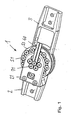
- FIG. 1 shows a top view of a fully assembled joint device 1 with an upper part 2 and a lower part 3.
- the term upper part and lower part means no technical limitation to a specific arrangement, but an upper part can be arranged both at the proximal and distal end of a prosthesis or orthosis, The same applies accordingly for the lower part.
- the upper part 2 has an L-shaped bracket 21 which is axially slidably connected to the upper part 2, screwed or placed. About screws 71 is a stop surfaces, which is not shown in this figure, bolted to the bracket 21.
- an actuating lever 40 protrudes in the direction of the lower part 3 and can by an actuator, not shown in FIG be pivoted about a pivot axis 4 both directions.
- the lever 40 is pivotally mounted relative to the upper part 2 and moves a coil spring which is non-rotatably attached to the lower part 3 via screws 51 on the lower part 3.
- the upper part 2 and the lower part 3 can be fastened to fastening elements of orthoses or prostheses.
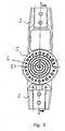
- FIG. 2 is a bottom view of the hinge device 1 is shown.
- the upper part 2 forms a support surface on which the second contact surface is rotatably mounted via screws 61 and connected to a functional unit.
- the lower part 3 is pivotable relative to the upper part 2 about a central pivot axis 4.
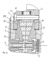
- FIG. 3 shows a sectional view through the upper part 2, the lower part 3 and the coil spring 5.
- the bracket 21, the lever 40 and the upper circular lid 53 are not shown.
- the coil spring 5 is rotatably mounted on the circumferentially distributed screws 51 on the lower part 3. It has a circular cross section with a catchy spiral passage which extends from the outside to the rotation axis 4, counterclockwise, spirally inwards. Parallel to the pivot axis 4 and coincident with this, the coil spring 5 can be braced by an actuation of the lever 40 counterclockwise in the winding direction, so that the coil spring 5 contracts inwardly in the direction of the axis of rotation 4.
- the individual spiral paths migrate inwards and then lie against the contact surfaces 6, 7, which are non-rotatably mounted on the upper part 2 via the screws 61, 71.
- the structural design and the operation of the hinge device 1 can be particularly well recognized.
- the upper part 2 and the lower part 3 against each other pivotally mounted about the pivot axis 4 displaceable together.
- contact surfaces 6, 7 are rotatably mounted via the screws 61, 71.
- the contact surfaces 6, 7 have a conical contour and are arranged relative to one another such that an expanding wedge space forms radially outward.
- the coil spring 5 is arranged, which is rotatably secured by the distributed at its periphery screws 51 on the lower part 3.
- the coil spring 5 is on the one hand directly on the lower part 3 and on the other hand on the lid 53.
- the lever 40 is also pivotable about the axis of rotation 4, which is also the Verspannachse stored and acts on the center of the coil spring 5. If the lever 40, as in the FIG. 1 shown, operated counterclockwise, the coil spring 5 braced inwards. The individual spiral gears with their conical contour try to move inwards. However, this is not possible because of the lateral limitations by the contact surfaces 6, 7, which act as brake discs. The lateral surfaces of the coil spring 5 wedged against the stop surfaces 6, 7, whereby a braking or a locking torque is realized. If, on the other hand, the lever is moved counterclockwise in the direction of the winding, the spiral turns widen outwards.
- the friction between the lateral spiral surfaces and the contact surfaces 6, 7 is reduced or eliminated, so that in extreme cases there is no longer any contact between the coil spring 5 and the contact surfaces 6, 7.
- the joint or the joint direction 1 can thus be moved freely. If an actually locked joint or a locked joint device 1 is moved counter to the winding direction of the coil spring 5, the friction between the side surfaces of the coil spring 5 and the contact surfaces 6, 7 causes a widening of the spiral gears, so that the joint is always free in this direction moves while automatically locking in an opposite direction of movement.
- the Normakraft necessary to build up the braking or locking torque acts perpendicular to the respective wedge surface.
- the components such as coil spring 5 and thrust surfaces 6, 7 at a predetermined braking torque
- two contact surfaces 6, 7 are provided. These contact surfaces 6, 7 are pushed apart when locking the hinge device 1 and thus rub against the spring fifth
- the coil spring 5 can be braced or relaxed, whereby the joint or the hinge device 1 is either opened or locked.
- a lever 40 may also serve a gear or a gear segment. Via a gear transmission can then take place an immediate coupling of a servomotor as an actuator to the gear and about with the coil spring or the coil springs, whereby the required space can be reduced.
- An adaptation to changing force relationships can take place via a change in the lever length at an operating lever via a change in the translation.
- a radial sliding bearing 8 is provided between the upper part 2, 21 and the lower part 3, which bears against end faces of the contact surfaces 6, 7 and the upper part 2 and the bracket 21.
- the radial bearing 8 does not have to rest on the end faces, it is important that it is secured against excessive axial displacements.
- a sliding around the pivot axis 4 is made possible when the spiral spring 5 is not tensioned.
- an angle sensor 9 can be seen, which senses the angular position of the upper part 2 to the lower part 3 and passes this data to a control device, which in turn actuates an actuator, not shown, for example, a servo or servo motor.
- an actuator not shown, for example, a servo or servo motor.
- a torque sensor may be integrated in the structure in the upper part 2 or preferably in the lower part 3.
- the lid 53 can be screwed directly to the lower part 3 via a thread, wherein an anti-twist device is provided.
- the gap can be set via the thread and the parts held together.
- bracket 21 In order to avoid unwanted tension, it may be necessary that the upper part 2 and the attached bracket 21 allow axial play, so that the two braking or contact surfaces 6, 7 are axially displaced easily to each other. Then it is envisaged that the bracket 21 is fixed with play on the upper part 2 or via two bolts which allow axial displacement, are interconnected.
- the geometry of the spiral curve of the coil spring 5 has a strong influence on the characteristics of the joint device 1. Spirals with many turns have a longer actuation path than spirals with few turns, however, the realized braking torque can be set much finer. Non-linear spiral geometries are possible, for example, to achieve a progressive braking behavior or to optimize the load of the coil spring.
- the joint device 1 When used in knee joint orthoses or prostheses, it is provided that the joint device 1 is set in a locking mode, which guarantees that the joint is not freely pivotable in the event of a failure of the actuator. This can be achieved by a bias of the actuating lever 40, for example via a spring, in a locked position.
- the opening of the hinge device or the braking device is then active against a spring force, for example, against a bias on the coil spring 5.
- a separate spring may be provided, which simultaneously causes automatic wear compensation.
- the opening of the hinge device 1 is then actively against the spring force. If the bias voltage is selected in opposition to the actuator in the middle of the torque range of interest, the braking torque to be realized can be further strengthened or weakened.
- two coil springs can be arranged axially next to one another in the opposite direction, so that a brake effective in both pivot directions can be obtained, which requires few components and can be switched under load in both directions of movement.
- the above-described joint device can also be used with any number of spinning components and is therefore also suitable for overrunning clutches or backstops.
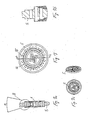
- FIG. 6 is a plan view of a coil spring 5 with Euler's spiral gears, so shown a linear spiral geometry. A total of four spiral paths are provided, each with three and a half turns, so that due to the relatively large surface of the spiral gears results in a relatively easy adjustment and rotatability of the coil spring 5.
- FIG. 6a in which a section along the line AA in the FIG. 6 is shown, the arrangement of the coil spring 5 between two contact surfaces 6, 7 can be seen.
- bores 55 are formed, through which the fastening screws or bolts 51 can be passed through in order to fix the coil spring on the lower part 3.
- the wedge angle ⁇ of the coil spring 5 located between 10 ° and 50 °, in this case at about 30 °.
- the wedge angle ⁇ is at the same time the wedge angle which is formed between the contact surfaces 6, 7.
- the wedge angle ⁇ is oriented the other way around.
- FIG. 6b shows the enlarged partial view of the area B from the FIG. 6a .
- FIG. 7 a coil spring 5 is shown in plan view with a non-linear spiral geometry.
- the coil spring 5 has four spiral gears with a winding length of about 225 °, resulting in a much stiffer spring characteristic than in the coil spring 5 of FIG. 6 results.
- Also in the coil spring 5 according to the FIG. 7 are bores 55 distributed on the circumference of the coil spring 5, in this case in a larger number than in the coil spring according to the figure 6. Smaller holes 56 are used to save material, but can also be used together with bolts for torque transmission.
- the FIG. 7c shows the cup-like depression to the axis of rotation 4 out.
- FIG. 8 shows in a partial sectional view, similar to that of FIG. 5 , An alternative embodiment of the hinge device.
- splines 30, 530 are incorporated in the lower part 3 and the lid, in which friction plates 531, 532, 533, 31, 32, 33 are axially displaceable and rotatably inserted.
- the spline 30 and bolts or other positive connection elements can be provided.
- the rotationally fixed bearing can be produced by a positive connection of projections on the circumference of the lamellae 31, 32, 33, 531, 532, 533 and grooves and notches in the lower part 3 and cover 53.
- a final friction pair is by the area between a the upper part 2 associated output member 73, 64 and the lid 53 and the lower part 3 realized.
- a total of 16 friction surface pairings are provided, whereby the friction surface can be substantially increased.
Landscapes
- Health & Medical Sciences (AREA)
- Transplantation (AREA)
- Animal Behavior & Ethology (AREA)
- Engineering & Computer Science (AREA)
- Biomedical Technology (AREA)
- Heart & Thoracic Surgery (AREA)
- Vascular Medicine (AREA)
- Life Sciences & Earth Sciences (AREA)
- Orthopedic Medicine & Surgery (AREA)
- General Health & Medical Sciences (AREA)
- Public Health (AREA)
- Veterinary Medicine (AREA)
- Nursing (AREA)
- Cardiology (AREA)
- Oral & Maxillofacial Surgery (AREA)
- Pivots And Pivotal Connections (AREA)
- Prostheses (AREA)
- Devices For Conveying Motion By Means Of Endless Flexible Members (AREA)
- Medicines Containing Material From Animals Or Micro-Organisms (AREA)
- Colloid Chemistry (AREA)
- Pharmaceuticals Containing Other Organic And Inorganic Compounds (AREA)
- Vibration Prevention Devices (AREA)
- Separation By Low-Temperature Treatments (AREA)
- Joints Allowing Movement (AREA)
- Compression-Type Refrigeration Machines With Reversible Cycles (AREA)
- Manipulator (AREA)
Claims (20)
- Dispositif d'articulation pour des orthèses ou des prothèses, comprenant une partie supérieure (2) et une partie inférieure (3) montée rotative sur la partie supérieure autour d'un axe de pivotement, et un dispositif de freinage qui freine ou bloque un mouvement de pivotement de la partie inférieure relativement à la partie supérieure, le dispositif d'articulation présentant un ressort en spirale (5) qui est monté autour d'un axe de déformation rotative (4) en étant serrable parallèlement à l'axe de pivotement, caractérisé en ce que le ressort en spirale (5) est agencé entre deux pistes (6, 7) et entre en contact avec celles-ci lors du serrage vers les pistes (6, 7).
- Dispositif d'articulation selon la revendication 1, caractérisé en ce que l'axe de déformation rotative (4) coïncide avec l'axe de pivotement.
- Dispositif d'articulation selon la revendication 2, caractérisé en ce que la piste (6, 7) est formée conique radialement ou courbée radialement.
- Dispositif d'articulation selon la revendication 3, caractérisé en ce que le ressort en spirale (5) est contouré de façon correspondante au contour des pistes (6, 7).
- Dispositif d'articulation selon l'une des revendications 3 ou 4, caractérisé en ce que l'angle de cône α des pistes (6, 7) est compris entre 10° et 50°.
- Dispositif d'articulation selon l'une des revendications précédentes, caractérisé en ce que le ressort en spirale (5) est ajustable en tension.
- Dispositif d'articulation selon l'une des revendications précédentes, caractérisé en ce que le ressort en spirale (5) est en contact avec les pistes (6, 7) dans sa position initiale.
- Dispositif d'articulation selon l'une des revendications précédentes, caractérisé en ce que le ressort en spirale (5) est couplé avec un actuateur qui serre le ressort en spirale (5) contre les pistes (6, 7) dans la direction d'enroulement de la spirale, ou à l'opposé.
- Dispositif d'articulation selon la revendication 8, caractérisé en ce que l'actuateur est un servomoteur.
- Dispositif d'articulation selon la revendication 8 ou 9, caractérisé en ce que l'actuateur est couplé avec le ressort en spirale (5) par l'intermédiaire d'un levier (40) ou une roue dentée ou portion de roue dentée.
- Dispositif d'articulation selon la revendication 10, caractérisé en ce que le levier (40) ou la roue dentée est sollicitée par ressort dans la direction de verrouillage.
- Dispositif d'articulation selon l'une des revendications 8 à 11, caractérisé en ce que dans sa position initiale le ressort en spirale (5) est préserré contre l'actuateur, dans la direction de verrouillage.
- Dispositif d'articulation selon l'une des revendications 8 à 12, caractérisé en ce qu'il est prévu un dispositif capteur (9) qui mesure les forces, moments et/ou positions angulaires des parties inférieure et supérieure (2, 3) l'une par rapport à l'autre, et qui est couplé à une unité de commande qui, en fonction des grandeurs mesurées, active l'actuateur et serre le ressort en spirale (5).
- Dispositif d'articulation selon l'une des revendications 8 à 13, caractérisé en ce que l'actuateur est commandé par l'intermédiaire de signaux myoélectriques.
- Dispositif d'articulation selon l'une des revendications 8 à 14, caractérisé en ce qu'un dispositif pour relever l'orientation spatiale de la partie supérieure et/ou de la partie inférieure, est couplé avec l'actuateur.
- Dispositif d'articulation selon l'une des revendications 8 à 15, caractérisé en ce qu'un dispositif pour relever les accélérations de la partie supérieure et/ou de la partie inférieure et/ou de dispositifs qui y sont fixés, accélérations survenant dans l'orthèse, est couplé avec l'actuateur.
- Dispositif d'articulation selon l'une des revendications précédentes, caractérisé en ce qu'au moins une piste (6, 7) est montée déplaçable axialement.
- Dispositif d'articulation selon l'une des revendications précédentes, caractérisé en ce que le ressort en spirale (5) est formé à pas multiples.
- Dispositif d'articulation selon l'une des revendications précédentes, caractérisé en ce que le ressort en spirale (5) présente une géométrie de spirale non linéaire.
- Dispositif d'articulation selon l'une des revendications précédentes, caractérisé en ce que les pistes (6, 7) sont couplées avec un ensemble de lamelles pour augmenter le nombre des surfaces de frottement.
Applications Claiming Priority (2)
| Application Number | Priority Date | Filing Date | Title |
|---|---|---|---|
| DE102006012716A DE102006012716B3 (de) | 2006-03-17 | 2006-03-17 | Gelenkeinrichtung |
| PCT/DE2007/000499 WO2007107150A1 (fr) | 2006-03-17 | 2007-03-15 | Dispositif d'articulation |
Publications (2)
| Publication Number | Publication Date |
|---|---|
| EP1996128A1 EP1996128A1 (fr) | 2008-12-03 |
| EP1996128B1 true EP1996128B1 (fr) | 2009-10-21 |
Family
ID=38169352
Family Applications (1)
| Application Number | Title | Priority Date | Filing Date |
|---|---|---|---|
| EP07711243A Not-in-force EP1996128B1 (fr) | 2006-03-17 | 2007-03-15 | Dispositif d'articulation |
Country Status (9)
| Country | Link |
|---|---|
| US (1) | US7935153B2 (fr) |
| EP (1) | EP1996128B1 (fr) |
| JP (1) | JP4819914B2 (fr) |
| CN (1) | CN101404959B (fr) |
| AT (1) | ATE446063T1 (fr) |
| DE (2) | DE102006012716B3 (fr) |
| RU (1) | RU2406467C2 (fr) |
| TW (1) | TWI317633B (fr) |
| WO (1) | WO2007107150A1 (fr) |
Cited By (2)
| Publication number | Priority date | Publication date | Assignee | Title |
|---|---|---|---|---|
| WO2023281062A1 (fr) * | 2021-07-09 | 2023-01-12 | Otto Bock Healthcare Products Gmbh | Dispositif d'articulation orthopédique |
| WO2023281023A1 (fr) * | 2021-07-09 | 2023-01-12 | Otto Bock Healthcare Products Gmbh | Dispositif d'articulation orthopédique |
Families Citing this family (33)
| Publication number | Priority date | Publication date | Assignee | Title |
|---|---|---|---|---|
| US10842653B2 (en) | 2007-09-19 | 2020-11-24 | Ability Dynamics, Llc | Vacuum system for a prosthetic foot |
| DE102008024748A1 (de) | 2008-05-20 | 2009-12-03 | Otto Bock Healthcare Gmbh | Knieorthese sowie Verfahren zum Steuern einer Knieorthese |
| US20110213599A1 (en) * | 2008-08-28 | 2011-09-01 | Raytheon Company | Method of Sizing Actuators for a Biomimetic Mechanical Joint |
| WO2010025403A1 (fr) | 2008-08-28 | 2010-03-04 | Raytheon Sarcos, Llc | Logique de commande pour actionneurs d'articulation biomimétiques |
| CN102196785B (zh) * | 2008-08-28 | 2014-02-26 | 雷神公司 | 仿生机械关节 |
| DE102008059907A1 (de) * | 2008-12-02 | 2010-06-10 | Otto Bock Healthcare Gmbh | Orthopädietechnisches Gelenk |
| DE102009018179B4 (de) | 2009-04-22 | 2014-07-10 | Otto Bock Healthcare Gmbh | Strukturelement für eine orthopädietechnische Einrichtung und orthopädische Einrichtung |
| WO2011052032A1 (fr) * | 2009-10-27 | 2011-05-05 | トヨタ自動車株式会社 | Dispositif d'aide à la marche |
| JP5428877B2 (ja) * | 2010-01-12 | 2014-02-26 | トヨタ自動車株式会社 | 歩行補助装置 |
| WO2011138782A2 (fr) * | 2010-05-04 | 2011-11-10 | Lifshitz, Achiam | Articulation artificielle sécurisée |
| JP5316708B2 (ja) * | 2010-12-16 | 2013-10-16 | トヨタ自動車株式会社 | 歩行支援装置 |
| US8715367B1 (en) * | 2011-06-10 | 2014-05-06 | Fillauer Companies, Inc. | Apparatus and method for an orthotic and prosthetic joint |
| US8777195B2 (en) | 2011-09-23 | 2014-07-15 | Adicep Technologies, Inc. | Non-linear torsion spring assembly |
| DE102012003369A1 (de) | 2012-02-22 | 2013-08-22 | Otto Bock Healthcare Gmbh | Verfahren zur Steuerung eines künstlichen Orthesen- oder Prothesenkniegelenks |
| GB2524668A (en) | 2012-09-10 | 2015-09-30 | Acumed Llc | Radial head prosthesis with floating articular member |
| USD712048S1 (en) * | 2013-01-23 | 2014-08-26 | Ossur Hf | Strap dosing system including a sleeve |
| DE102013013810B3 (de) * | 2013-08-22 | 2015-02-19 | Otto Bock Healthcare Products Gmbh | Verfahren zur Steuerung eines künstlichen Orthesen- oder Prothesenkniegelenkes |
| TWI552743B (zh) * | 2013-12-19 | 2016-10-11 | Hiwin Tech Corp | Inductive force feedback mechanism |
| JP5925221B2 (ja) * | 2014-01-21 | 2016-05-25 | 上銀科技股▲分▼有限公司 | 感応式力フィードバック装置 |
| US9763792B2 (en) | 2015-10-01 | 2017-09-19 | Acumed Llc | Radial head prosthesis with rotate-to-lock interface |
| CA2920670C (fr) * | 2016-02-12 | 2025-09-16 | Derek Nolt | Supports d'epaule et methodes d'utilisation |
| US12150880B2 (en) * | 2016-05-03 | 2024-11-26 | Icarus Medical, LLC | Joint brace with distracting hinge |
| US11806264B2 (en) * | 2016-05-03 | 2023-11-07 | Icarus Medical, LLC | Adjustable tensioning device |
| USD819212S1 (en) * | 2016-07-18 | 2018-05-29 | Weber Orthopedic, Inc. | Orthopedic hinge |
| DE102016114834A1 (de) * | 2016-08-10 | 2018-02-15 | Otto Bock Healthcare Gmbh | Gelenk für eine orthopädische Einrichtung |
| DE102017122741A1 (de) * | 2016-10-03 | 2018-04-26 | Jtekt Corporation | Assistenzvorrichtung |
| JP6838341B2 (ja) * | 2016-10-03 | 2021-03-03 | 株式会社ジェイテクト | アシスト装置 |
| EP3589241B1 (fr) | 2017-03-02 | 2024-08-07 | Proteor USA, LLC | Genou prothétique avec système hydraulique de rectification |
| DE102017112911B4 (de) * | 2017-06-12 | 2024-09-05 | Otto Bock Healthcare Products Gmbh | Gelenkeinrichtung |
| US11246720B2 (en) | 2019-11-26 | 2022-02-15 | Hugh Steeper Limited | Prosthetic elbow with adjustable counterbalance mechanism |
| CN111920655B (zh) * | 2020-09-27 | 2021-03-02 | 上海傅利叶智能科技有限公司 | 一种足托初始角度可调的踝关节装置 |
| RU206347U1 (ru) * | 2021-06-21 | 2021-09-07 | Никита Анатольевич Липович | Автоматизированный механизм подвижности коленного сустава для реабилитаци |
| US12611313B2 (en) | 2023-04-06 | 2026-04-28 | 33 Medical, Inc. | Minimally invasive compliant devices for total lumbar disc replacement |
Family Cites Families (13)
| Publication number | Priority date | Publication date | Assignee | Title |
|---|---|---|---|---|
| DE295807C (fr) | ||||
| DE329908C (de) * | 1920-12-02 | Hugo Lowitzsch | Kuenstliches Kniegelenk mit spiralfoermiger Streckungsfeder | |
| SU35968A1 (ru) * | 1933-01-23 | 1934-04-30 | Н.А. Яковлев | Протез нижней конечности |
| SU1109154A1 (ru) * | 1983-05-30 | 1984-08-23 | Специальное Конструкторско-Технологическое Бюро Института Технической Механики Ан Усср | Коленный шарнир протеза |
| JPH032320A (ja) * | 1989-05-29 | 1991-01-08 | Nippon Steel Corp | Fe―Al―Cr系合金鋼の圧延方法 |
| GB2244006B (en) * | 1990-05-04 | 1994-05-25 | Blatchford & Sons Ltd | An artificial limb |
| DE4324399C1 (de) * | 1993-07-21 | 1995-02-09 | Bock Orthopaed Ind | Ellbogenlifter |
| DE9320708U1 (de) * | 1993-07-21 | 1994-12-01 | Otto Bock Orthopädische Industrie Besitz- und Verwaltungs-Kommanditgesellschaft, 37115 Duderstadt | Ellbogenlifter |
| US5873847A (en) * | 1996-11-14 | 1999-02-23 | Lenjoy Engineering, Inc. | Articulated splints and goniometric hinge for the same |
| DE19810385C2 (de) * | 1998-03-11 | 2000-06-21 | Bock Orthopaed Ind | Prothesenbremsgelenk |
| SE516991C2 (sv) * | 1998-04-28 | 2002-04-02 | Gramtec Innovation Ab | Knäledsprotes |
| US6471664B1 (en) * | 2000-03-15 | 2002-10-29 | Becker Orthopedic Appliance Company | Knee joint and method |
| ATE394081T1 (de) * | 2000-05-27 | 2008-05-15 | Ohio Willow Wood Co | Dämpfer für rotationsbewegungen bei prothesen |
-
2006
- 2006-03-17 DE DE102006012716A patent/DE102006012716B3/de not_active Expired - Fee Related
-
2007
- 2007-03-01 TW TW096106934A patent/TWI317633B/zh not_active IP Right Cessation
- 2007-03-15 JP JP2008558635A patent/JP4819914B2/ja not_active Expired - Fee Related
- 2007-03-15 CN CN2007800094261A patent/CN101404959B/zh not_active Expired - Fee Related
- 2007-03-15 EP EP07711243A patent/EP1996128B1/fr not_active Not-in-force
- 2007-03-15 RU RU2008139211/14A patent/RU2406467C2/ru not_active IP Right Cessation
- 2007-03-15 DE DE502007001802T patent/DE502007001802D1/de active Active
- 2007-03-15 US US12/293,319 patent/US7935153B2/en active Active
- 2007-03-15 AT AT07711243T patent/ATE446063T1/de active
- 2007-03-15 WO PCT/DE2007/000499 patent/WO2007107150A1/fr not_active Ceased
Cited By (2)
| Publication number | Priority date | Publication date | Assignee | Title |
|---|---|---|---|---|
| WO2023281062A1 (fr) * | 2021-07-09 | 2023-01-12 | Otto Bock Healthcare Products Gmbh | Dispositif d'articulation orthopédique |
| WO2023281023A1 (fr) * | 2021-07-09 | 2023-01-12 | Otto Bock Healthcare Products Gmbh | Dispositif d'articulation orthopédique |
Also Published As
| Publication number | Publication date |
|---|---|
| DE502007001802D1 (de) | 2009-12-03 |
| TWI317633B (en) | 2009-12-01 |
| TW200800125A (en) | 2008-01-01 |
| DE102006012716B3 (de) | 2008-01-17 |
| WO2007107150A1 (fr) | 2007-09-27 |
| CN101404959A (zh) | 2009-04-08 |
| EP1996128A1 (fr) | 2008-12-03 |
| JP2009529927A (ja) | 2009-08-27 |
| ATE446063T1 (de) | 2009-11-15 |
| US20090076618A1 (en) | 2009-03-19 |
| RU2008139211A (ru) | 2010-04-27 |
| CN101404959B (zh) | 2011-02-23 |
| JP4819914B2 (ja) | 2011-11-24 |
| US7935153B2 (en) | 2011-05-03 |
| RU2406467C2 (ru) | 2010-12-20 |
Similar Documents
| Publication | Publication Date | Title |
|---|---|---|
| EP1996128B1 (fr) | Dispositif d'articulation | |
| DE102006020777B4 (de) | Prothesengelenk | |
| EP1568905A1 (fr) | Embrayage à réglage automatique | |
| EP1962738A1 (fr) | Accouplement de commutation destine a des protheses | |
| EP2247811B1 (fr) | Commande d'actionnement pour un abattant de meuble, avec une securite de montage pour le bras d'actionnement vide | |
| DE60026564T2 (de) | Nachstellstrebe | |
| DE10084336B3 (de) | Steuervorrichtung für ein Kopplungsmittel mit veränderlicher Kraftdosierung | |
| EP3445544A1 (fr) | Articulation motorisée pour un automate de déplacement programmable | |
| EP3352713B1 (fr) | Support dynamique d'articulation | |
| EP1957816A1 (fr) | Organe d'embrayage | |
| EP2748028B1 (fr) | Ferrure de réglage pourvue d'un système de blocage axial destiné à sécuriser le fonctionnement | |
| EP1957815A1 (fr) | Organe d'embrayage | |
| EP4013360B1 (fr) | Système constitué d'un adaptateur à ressort et d'un système d'articulation orthopédique | |
| WO2012079552A1 (fr) | Module de porte | |
| DE10361148A1 (de) | Verstellvorrichtung zur Erzeugung einer beidseitigen Drehbewegung | |
| DE102016010484A1 (de) | Torsionsschwingungsdämpfer und Anordnung für den Antriebsstrang eines Kraftfahrzeugs mit einem solchen Torsionsschwingungsdämpfer | |
| DE102008059907A1 (de) | Orthopädietechnisches Gelenk | |
| EP3713522B1 (fr) | Articulation avec frein | |
| DE102021117835A1 (de) | Orthopädietechnische Gelenkeinrichtung | |
| DE102020120498A1 (de) | Prothesenfuß | |
| EP3926202B1 (fr) | Dispositif á ressort et actionneur hydraulique | |
| DE102009036222A1 (de) | Innenbackenbremse mit thermisch geregelter Nachstelleinrichtung für das Bremsbackenlüftspiel | |
| DE10236516A1 (de) | Elektromechanische Kupplung und elektromechanisches System | |
| EP2910282B1 (fr) | Clapet anti-feu | |
| DE102021117836A1 (de) | Orthopädietechnische Gelenkeinrichtung |
Legal Events
| Date | Code | Title | Description |
|---|---|---|---|
| PUAI | Public reference made under article 153(3) epc to a published international application that has entered the european phase |
Free format text: ORIGINAL CODE: 0009012 |
|
| 17P | Request for examination filed |
Effective date: 20080930 |
|
| AK | Designated contracting states |
Kind code of ref document: A1 Designated state(s): AT BE BG CH CY CZ DE DK EE ES FI FR GB GR HU IE IS IT LI LT LU LV MC MT NL PL PT RO SE SI SK TR |
|
| GRAP | Despatch of communication of intention to grant a patent |
Free format text: ORIGINAL CODE: EPIDOSNIGR1 |
|
| GRAS | Grant fee paid |
Free format text: ORIGINAL CODE: EPIDOSNIGR3 |
|
| GRAA | (expected) grant |
Free format text: ORIGINAL CODE: 0009210 |
|
| AK | Designated contracting states |
Kind code of ref document: B1 Designated state(s): AT BE BG CH CY CZ DE DK EE ES FI FR GB GR HU IE IS IT LI LT LU LV MC MT NL PL PT RO SE SI SK TR |
|
| REG | Reference to a national code |
Ref country code: GB Ref legal event code: FG4D Free format text: NOT ENGLISH |
|
| REG | Reference to a national code |
Ref country code: CH Ref legal event code: EP |
|
| REG | Reference to a national code |
Ref country code: IE Ref legal event code: FG4D |
|
| REG | Reference to a national code |
Ref country code: CH Ref legal event code: NV Representative=s name: BRAUNPAT BRAUN EDER AG |
|
| REF | Corresponds to: |
Ref document number: 502007001802 Country of ref document: DE Date of ref document: 20091203 Kind code of ref document: P |
|
| LTIE | Lt: invalidation of european patent or patent extension |
Effective date: 20091021 |
|
| PG25 | Lapsed in a contracting state [announced via postgrant information from national office to epo] |
Ref country code: SE Free format text: LAPSE BECAUSE OF FAILURE TO SUBMIT A TRANSLATION OF THE DESCRIPTION OR TO PAY THE FEE WITHIN THE PRESCRIBED TIME-LIMIT Effective date: 20091021 Ref country code: FI Free format text: LAPSE BECAUSE OF FAILURE TO SUBMIT A TRANSLATION OF THE DESCRIPTION OR TO PAY THE FEE WITHIN THE PRESCRIBED TIME-LIMIT Effective date: 20091021 Ref country code: LT Free format text: LAPSE BECAUSE OF FAILURE TO SUBMIT A TRANSLATION OF THE DESCRIPTION OR TO PAY THE FEE WITHIN THE PRESCRIBED TIME-LIMIT Effective date: 20091021 Ref country code: PT Free format text: LAPSE BECAUSE OF FAILURE TO SUBMIT A TRANSLATION OF THE DESCRIPTION OR TO PAY THE FEE WITHIN THE PRESCRIBED TIME-LIMIT Effective date: 20100222 Ref country code: ES Free format text: LAPSE BECAUSE OF FAILURE TO SUBMIT A TRANSLATION OF THE DESCRIPTION OR TO PAY THE FEE WITHIN THE PRESCRIBED TIME-LIMIT Effective date: 20100201 Ref country code: IS Free format text: LAPSE BECAUSE OF FAILURE TO SUBMIT A TRANSLATION OF THE DESCRIPTION OR TO PAY THE FEE WITHIN THE PRESCRIBED TIME-LIMIT Effective date: 20100221 |
|
| REG | Reference to a national code |
Ref country code: IE Ref legal event code: FD4D |
|
| PG25 | Lapsed in a contracting state [announced via postgrant information from national office to epo] |
Ref country code: SI Free format text: LAPSE BECAUSE OF FAILURE TO SUBMIT A TRANSLATION OF THE DESCRIPTION OR TO PAY THE FEE WITHIN THE PRESCRIBED TIME-LIMIT Effective date: 20091021 Ref country code: CY Free format text: LAPSE BECAUSE OF FAILURE TO SUBMIT A TRANSLATION OF THE DESCRIPTION OR TO PAY THE FEE WITHIN THE PRESCRIBED TIME-LIMIT Effective date: 20091021 Ref country code: LV Free format text: LAPSE BECAUSE OF FAILURE TO SUBMIT A TRANSLATION OF THE DESCRIPTION OR TO PAY THE FEE WITHIN THE PRESCRIBED TIME-LIMIT Effective date: 20091021 Ref country code: PL Free format text: LAPSE BECAUSE OF FAILURE TO SUBMIT A TRANSLATION OF THE DESCRIPTION OR TO PAY THE FEE WITHIN THE PRESCRIBED TIME-LIMIT Effective date: 20091021 |
|
| PG25 | Lapsed in a contracting state [announced via postgrant information from national office to epo] |
Ref country code: BG Free format text: LAPSE BECAUSE OF FAILURE TO SUBMIT A TRANSLATION OF THE DESCRIPTION OR TO PAY THE FEE WITHIN THE PRESCRIBED TIME-LIMIT Effective date: 20100121 Ref country code: RO Free format text: LAPSE BECAUSE OF FAILURE TO SUBMIT A TRANSLATION OF THE DESCRIPTION OR TO PAY THE FEE WITHIN THE PRESCRIBED TIME-LIMIT Effective date: 20091021 Ref country code: IE Free format text: LAPSE BECAUSE OF FAILURE TO SUBMIT A TRANSLATION OF THE DESCRIPTION OR TO PAY THE FEE WITHIN THE PRESCRIBED TIME-LIMIT Effective date: 20091021 Ref country code: EE Free format text: LAPSE BECAUSE OF FAILURE TO SUBMIT A TRANSLATION OF THE DESCRIPTION OR TO PAY THE FEE WITHIN THE PRESCRIBED TIME-LIMIT Effective date: 20091021 Ref country code: DK Free format text: LAPSE BECAUSE OF FAILURE TO SUBMIT A TRANSLATION OF THE DESCRIPTION OR TO PAY THE FEE WITHIN THE PRESCRIBED TIME-LIMIT Effective date: 20091021 |
|
| PLBE | No opposition filed within time limit |
Free format text: ORIGINAL CODE: 0009261 |
|
| STAA | Information on the status of an ep patent application or granted ep patent |
Free format text: STATUS: NO OPPOSITION FILED WITHIN TIME LIMIT |
|
| PG25 | Lapsed in a contracting state [announced via postgrant information from national office to epo] |
Ref country code: SK Free format text: LAPSE BECAUSE OF FAILURE TO SUBMIT A TRANSLATION OF THE DESCRIPTION OR TO PAY THE FEE WITHIN THE PRESCRIBED TIME-LIMIT Effective date: 20091021 Ref country code: CZ Free format text: LAPSE BECAUSE OF FAILURE TO SUBMIT A TRANSLATION OF THE DESCRIPTION OR TO PAY THE FEE WITHIN THE PRESCRIBED TIME-LIMIT Effective date: 20091021 |
|
| 26N | No opposition filed |
Effective date: 20100722 |
|
| BERE | Be: lapsed |
Owner name: OTTO BOCK HEALTHCARE IP G.M.B.H. & CO. KG Effective date: 20100331 |
|
| PG25 | Lapsed in a contracting state [announced via postgrant information from national office to epo] |
Ref country code: MC Free format text: LAPSE BECAUSE OF NON-PAYMENT OF DUE FEES Effective date: 20100331 Ref country code: GR Free format text: LAPSE BECAUSE OF FAILURE TO SUBMIT A TRANSLATION OF THE DESCRIPTION OR TO PAY THE FEE WITHIN THE PRESCRIBED TIME-LIMIT Effective date: 20100122 |
|
| PG25 | Lapsed in a contracting state [announced via postgrant information from national office to epo] |
Ref country code: BE Free format text: LAPSE BECAUSE OF NON-PAYMENT OF DUE FEES Effective date: 20100331 |
|
| PG25 | Lapsed in a contracting state [announced via postgrant information from national office to epo] |
Ref country code: IT Free format text: LAPSE BECAUSE OF NON-PAYMENT OF DUE FEES Effective date: 20100315 |
|
| PG25 | Lapsed in a contracting state [announced via postgrant information from national office to epo] |
Ref country code: MT Free format text: LAPSE BECAUSE OF FAILURE TO SUBMIT A TRANSLATION OF THE DESCRIPTION OR TO PAY THE FEE WITHIN THE PRESCRIBED TIME-LIMIT Effective date: 20091021 |
|
| PG25 | Lapsed in a contracting state [announced via postgrant information from national office to epo] |
Ref country code: HU Free format text: LAPSE BECAUSE OF FAILURE TO SUBMIT A TRANSLATION OF THE DESCRIPTION OR TO PAY THE FEE WITHIN THE PRESCRIBED TIME-LIMIT Effective date: 20100422 Ref country code: LU Free format text: LAPSE BECAUSE OF NON-PAYMENT OF DUE FEES Effective date: 20100315 |
|
| REG | Reference to a national code |
Ref country code: AT Ref legal event code: MM01 Ref document number: 446063 Country of ref document: AT Kind code of ref document: T Effective date: 20120315 |
|
| PG25 | Lapsed in a contracting state [announced via postgrant information from national office to epo] |
Ref country code: AT Free format text: LAPSE BECAUSE OF NON-PAYMENT OF DUE FEES Effective date: 20120315 |
|
| REG | Reference to a national code |
Ref country code: DE Ref legal event code: R082 Ref document number: 502007001802 Country of ref document: DE Representative=s name: GRAMM, LINS & PARTNER PATENT- UND RECHTSANWAEL, DE |
|
| REG | Reference to a national code |
Ref country code: FR Ref legal event code: PLFP Year of fee payment: 10 |
|
| REG | Reference to a national code |
Ref country code: FR Ref legal event code: PLFP Year of fee payment: 11 |
|
| REG | Reference to a national code |
Ref country code: FR Ref legal event code: PLFP Year of fee payment: 12 |
|
| PGFP | Annual fee paid to national office [announced via postgrant information from national office to epo] |
Ref country code: CH Payment date: 20180326 Year of fee payment: 12 |
|
| REG | Reference to a national code |
Ref country code: CH Ref legal event code: PCAR Free format text: NEW ADDRESS: HOLEESTRASSE 87, 4054 BASEL (CH) |
|
| PGFP | Annual fee paid to national office [announced via postgrant information from national office to epo] |
Ref country code: IT Payment date: 20180322 Year of fee payment: 12 |
|
| PGFP | Annual fee paid to national office [announced via postgrant information from national office to epo] |
Ref country code: NL Payment date: 20190418 Year of fee payment: 13 |
|
| PGFP | Annual fee paid to national office [announced via postgrant information from national office to epo] |
Ref country code: TR Payment date: 20190408 Year of fee payment: 13 |
|
| REG | Reference to a national code |
Ref country code: CH Ref legal event code: PL |
|
| PG25 | Lapsed in a contracting state [announced via postgrant information from national office to epo] |
Ref country code: LI Free format text: LAPSE BECAUSE OF NON-PAYMENT OF DUE FEES Effective date: 20190331 Ref country code: CH Free format text: LAPSE BECAUSE OF NON-PAYMENT OF DUE FEES Effective date: 20190331 |
|
| PG25 | Lapsed in a contracting state [announced via postgrant information from national office to epo] |
Ref country code: IT Free format text: LAPSE BECAUSE OF NON-PAYMENT OF DUE FEES Effective date: 20190315 |
|
| REG | Reference to a national code |
Ref country code: NL Ref legal event code: MM Effective date: 20200401 |
|
| PG25 | Lapsed in a contracting state [announced via postgrant information from national office to epo] |
Ref country code: NL Free format text: LAPSE BECAUSE OF NON-PAYMENT OF DUE FEES Effective date: 20200401 |
|
| PG25 | Lapsed in a contracting state [announced via postgrant information from national office to epo] |
Ref country code: TR Free format text: LAPSE BECAUSE OF NON-PAYMENT OF DUE FEES Effective date: 20200315 |
|
| PGFP | Annual fee paid to national office [announced via postgrant information from national office to epo] |
Ref country code: FR Payment date: 20230320 Year of fee payment: 17 |
|
| PGFP | Annual fee paid to national office [announced via postgrant information from national office to epo] |
Ref country code: GB Payment date: 20230323 Year of fee payment: 17 Ref country code: DE Payment date: 20230320 Year of fee payment: 17 |
|
| REG | Reference to a national code |
Ref country code: DE Ref legal event code: R119 Ref document number: 502007001802 Country of ref document: DE |
|
| GBPC | Gb: european patent ceased through non-payment of renewal fee |
Effective date: 20240315 |
|
| PG25 | Lapsed in a contracting state [announced via postgrant information from national office to epo] |
Ref country code: DE Free format text: LAPSE BECAUSE OF NON-PAYMENT OF DUE FEES Effective date: 20241001 |
|
| PG25 | Lapsed in a contracting state [announced via postgrant information from national office to epo] |
Ref country code: GB Free format text: LAPSE BECAUSE OF NON-PAYMENT OF DUE FEES Effective date: 20240315 |
|
| PG25 | Lapsed in a contracting state [announced via postgrant information from national office to epo] |
Ref country code: FR Free format text: LAPSE BECAUSE OF NON-PAYMENT OF DUE FEES Effective date: 20240331 |
|
| PG25 | Lapsed in a contracting state [announced via postgrant information from national office to epo] |
Ref country code: GB Free format text: LAPSE BECAUSE OF NON-PAYMENT OF DUE FEES Effective date: 20240315 Ref country code: FR Free format text: LAPSE BECAUSE OF NON-PAYMENT OF DUE FEES Effective date: 20240331 Ref country code: DE Free format text: LAPSE BECAUSE OF NON-PAYMENT OF DUE FEES Effective date: 20241001 |