EP1996343B1 - Appareil de criblage - Google Patents
Appareil de criblage Download PDFInfo
- Publication number
- EP1996343B1 EP1996343B1 EP07726912A EP07726912A EP1996343B1 EP 1996343 B1 EP1996343 B1 EP 1996343B1 EP 07726912 A EP07726912 A EP 07726912A EP 07726912 A EP07726912 A EP 07726912A EP 1996343 B1 EP1996343 B1 EP 1996343B1
- Authority
- EP
- European Patent Office
- Prior art keywords
- shaft
- counter
- screening apparatus
- drive member
- screening
- Prior art date
- Legal status (The legal status is an assumption and is not a legal conclusion. Google has not performed a legal analysis and makes no representation as to the accuracy of the status listed.)
- Not-in-force
Links
- 238000012216 screening Methods 0.000 title claims description 55
- 230000008878 coupling Effects 0.000 claims description 21
- 238000010168 coupling process Methods 0.000 claims description 21
- 238000005859 coupling reaction Methods 0.000 claims description 21
- 238000007789 sealing Methods 0.000 claims description 13
- 230000009471 action Effects 0.000 claims description 3
- 230000000295 complement effect Effects 0.000 claims description 2
- 239000002245 particle Substances 0.000 claims description 2
- 238000000429 assembly Methods 0.000 description 7
- 230000008901 benefit Effects 0.000 description 4
- 230000000712 assembly Effects 0.000 description 3
- 238000010276 construction Methods 0.000 description 2
- 238000013461 design Methods 0.000 description 2
- 239000000428 dust Substances 0.000 description 2
- 230000000694 effects Effects 0.000 description 2
- 238000012546 transfer Methods 0.000 description 2
- 230000004075 alteration Effects 0.000 description 1
- 238000005461 lubrication Methods 0.000 description 1
- 238000003754 machining Methods 0.000 description 1
- 238000004519 manufacturing process Methods 0.000 description 1
- 238000000034 method Methods 0.000 description 1
- 238000012986 modification Methods 0.000 description 1
- 230000004048 modification Effects 0.000 description 1
- 230000000149 penetrating effect Effects 0.000 description 1
- 230000008569 process Effects 0.000 description 1
Images





Classifications
-
- B—PERFORMING OPERATIONS; TRANSPORTING
- B07—SEPARATING SOLIDS FROM SOLIDS; SORTING
- B07B—SEPARATING SOLIDS FROM SOLIDS BY SIEVING, SCREENING, SIFTING OR BY USING GAS CURRENTS; SEPARATING BY OTHER DRY METHODS APPLICABLE TO BULK MATERIAL, e.g. LOOSE ARTICLES FIT TO BE HANDLED LIKE BULK MATERIAL
- B07B1/00—Sieving, screening, sifting, or sorting solid materials using networks, gratings, grids, or the like
- B07B1/28—Moving screens not otherwise provided for, e.g. swinging, reciprocating, rocking, tilting or wobbling screens
-
- B—PERFORMING OPERATIONS; TRANSPORTING
- B07—SEPARATING SOLIDS FROM SOLIDS; SORTING
- B07B—SEPARATING SOLIDS FROM SOLIDS BY SIEVING, SCREENING, SIFTING OR BY USING GAS CURRENTS; SEPARATING BY OTHER DRY METHODS APPLICABLE TO BULK MATERIAL, e.g. LOOSE ARTICLES FIT TO BE HANDLED LIKE BULK MATERIAL
- B07B1/00—Sieving, screening, sifting, or sorting solid materials using networks, gratings, grids, or the like
- B07B1/42—Drive mechanisms, regulating or controlling devices, or balancing devices, specially adapted for screens
-
- B—PERFORMING OPERATIONS; TRANSPORTING
- B07—SEPARATING SOLIDS FROM SOLIDS; SORTING
- B07B—SEPARATING SOLIDS FROM SOLIDS BY SIEVING, SCREENING, SIFTING OR BY USING GAS CURRENTS; SEPARATING BY OTHER DRY METHODS APPLICABLE TO BULK MATERIAL, e.g. LOOSE ARTICLES FIT TO BE HANDLED LIKE BULK MATERIAL
- B07B1/00—Sieving, screening, sifting, or sorting solid materials using networks, gratings, grids, or the like
- B07B1/46—Constructional details of screens in general; Cleaning or heating of screens
Definitions
- the invention relates to a screening apparatus having a vibrating assembly.
- the invention relates to a screening apparatus with a vibrating shaft assembly for use in a horizontal screening apparatus.
- US-3442381 discloses a screening apparatus as defined in the preamble of Claim 1.
- the present invention provides a screening apparatus having a screening box movably mounted on a support means via biasing means, the screening box comprising a pair of opposing side walls and a vibrating means for vibrating the screening box relative to the support means, the vibrating means comprising means for housing three rotatable shafts and means for coupling the shaft housing means to the opposing side wells of the screening box, each shaft rotatably housed in the at least one shaft housing means, the vibrating means further comprising a throw generating means rotatably mounted on both ends of each shaft housing means, the throw generating means being releasably fixed to each shaft, drive means comprising a motor, shaft driver means on one end of each shaft and a flexible endless drive member coupled between the motor and the shaft driver means, each throw generating means being rotatable about the shaft housing means via the drive means and shafts to impart vibratory movement to the screening box, characterised in that the flexible endless drive member positively engages a drive member provided on the motor and the shaft driver means of each shaft, and
- the shafts are mounted on the screen box at substantially the same vertical height.
- the motor is located above the one or more shafts.
- the flexible endless drive member is arranged over the shaft driver means of the three shafts and the drive member so that the end shafts turn in a clockwise direction and the middle shaft turns in an anti-clockwise direction giving the vibration assembly an oval vibration action.
- a portion of the flexible endless drive member between the drive member of the motor and one end shaft driver means is inclined at approximately the same angle as the angle of vibration of the screening box.
- the drive member of the motor is a pulley.
- the flexible endless drive member is a belt and optionally the belt is double sided and has equally spaced teeth on both sides.
- each throw generating means is a hub lock assembly comprising a self aligning bearing and a counterweight.
- each hub lock assembly further comprises a tapered adapter sleeve mounted intermediate the shaft housing means and the self aligning bearing.
- the counterweight has two component parts movable relative to one another for modifying the angle and stroke of vibration of the screening box.
- the two component part counterweight has a first part comprising a cylindrical hub portion and a counter-weight portion and a second part comprising a counter-weight engaging over the cylindrical hub portion and against the counter-weight portion.
- the counter-weight portion and the counter-weight each define a number of bolt receiving bores which are in alignment at particular relative angular positions of the counter-weight portion and the counter-weight.
- bolts are located in the bolt receiving bores which are in alignment to fix the counter-weight portion and the counter-weight at particular relative angular positions.
- the cylindrical hub portion houses the self aligning bearing.
- the counterweight has a plurality of holes for receiving plug weights.
- the shaft coupling means are secured towards the ends of the shaft housing means by forming complementary screw threads on the shaft coupling means and the shaft housing means.
- a fixing and sealing plate incorporates a first and second seal, wherein the first seal provides a seal between the fixing and sealing plate and a backing plate of the sub-assembly housing and wherein the second seal provides a seal between fixing and sealing plate and shaft coupling means.
- respective sealing means are provided on the main housing cover of a shaft and between a support housing and the shaft housing means to prevent the ingress of foreign particles Into the flexible endless drive member compartment and the throw generating means compartment.
- the present invention has a number of advantages over vibrating assemblies known in the art.
- hubs or shaft coupling members are provided as an integral part of the shaft housing assembly as a flanged construction and require machining to ensure alignment.
- a vibrating assembly of any width can be made using the same hubs/shaft coupling members.
- the hubs/shaft coupling members are inserted onto shaft housings of the required length and secured thereto. As the parts used at either end of the shafts are the same, construction is simplified and parts are easily serviceable.
- the hubs/shaft coupling members self align when inserted onto the shaft housing and provide added structural strength to the assembly. Using the hubs/shaft coupling members provided by the present assembly ensures the vibrating load is transmitted to the backing plate of the assembly housing and then transferred to the screening decks and spread over a large area.
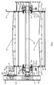
- the vibrating assembly 100 comprises two sub-assemblies 10, 11 located on either side of the apparatus with three shafts 1, 2, 3 extending between the sub-assemblies 10 and 11.
- the vibrating assembly 100 is mounted on a subframe 22 using rubber or coil springs 23 and spring mountings 18, 19, 20, 21, thereby facilitating vibration of the assembly 100.
- the screening apparatus illustrated is a two-deck screen box with screening media 27 held taut over screening decks 16, 17.
- the screening media 27 may be in a side tension configuration or in an in tension configuration for any embodiment of the invention.
- Both sub-assemblies 10, 11 have an identical set of components for each shaft except on the drive side of the vibrating assembly, where shafts 1, 2, 3 extend out through a main housing cover 25 into a timing belt compartment 26.
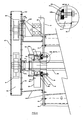
- Sub-assembly housings 12, 13 are secured to the screen box side plates 14, 15 using bolts. As each shaft 1, 2, 3 is identical, only shaft 3 as shown in Figures 2 and 4 is described.
- Shaft 3 extends between the vibrating sub-assemblies 10, 11 through a shaft housing 40 which comprises a shaft tube 42 and two shaft coupling members 41 inserted onto and secured towards the ends of the shaft tube 42.
- the shaft coupling members 41 are an interference fit on the shaft tube 42, they can be welded in place using welds without risk of misalignment.
- the shaft coupling members 41 can be secured to the shaft tube 42 by providing complimentary screw threads (not shown) on the ends of the shaft tube 42 and on the shaft coupling members 41.
- an O-ring seal 101 is mounted between the support housing 41 and the shaft tube 42.
- sub-assembly housing 12 is secured to the shaft coupling member 41 with an interference fit and by bolts 43 which pass through the screen box side plate 14 and the sub-assembly housing 12, and are secured to a fixing and sealing plate 46.
- the fixing and sealing plate 46 helps to secure the shaft coupling member 41 to the backing plate of the sub-assembly housing 12 and prevent oil leaking from the housing 12.
- the fixing and sealing plate 46 includes recesses for receiving O-ring seals 103 and 103b.
- O-ring seal 103 provides a seal between fixing and sealing plate 46 and the backing plate of the sub-assembly housing 12.
- O-ring seal 103b provides a seal between fixing and sealing plate 46 and shaft coupling member 41.
- Bolts 44 are also placed through the housing 12, the side plate 14 and the screening decks 16, 17.
- a hub lock assembly 53 is detachably secured to the shaft 3 and is rotatable about the shaft housing 42.
- the hub lock assembly 53 comprises an outer hub 54, a counter-weight 52 and a tapered adapter sleeve 70.
- the counter-weight 52 houses a self aligning bearing 50 which is mounted to the shaft housing 42 by means of the adapter sleeve 70.
- the self aligning bearing 50 is tightened onto the adapter sleeve 70 using nuts 51 and the adapter sleeve 70 is detachably fixed to the shaft housing 42.
- the counterweight 52 rotates along with the shaft 3 causing vibration of the vibrating assembly 100 which is transmitted to the backing plate of the sub assembly housing 12 and on to the screening decks 16, 17 of the screening box.
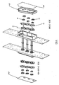
- Plug weights (not shown) can be inserted through holes 59 in the counterweight 52 ( Figure 3 ).
- a weight increase has the effect of increasing the stroke of vibration applied to the screen box.
- the shaft 3 extends through the main housing cover 25 into a timing belt compartment 26 on the drive side of the vibrating assembly 100.
- a seal 27a is provided on the shaft 3 at the main housing cover 25 to prevent oil leaking into the timing belt compartment 26.
- a timing pulley 6 is locked in place on the end of the shaft 3 using a keyed taper lock (not shown).
- a drive motor 60 is mounted on a sub-plate 62 and secured using bolts 61 through slots (not shown) on a plate 63. As shown in Figure 5 , the sub-plate 62 is additionally held in place by bolts 64 secured through a gusset 65. A drive pulley 66 is mounted on the motor 60 with a taper lock. A cover 67 is provided over the timing belt compartment 26 to create a dust free environment.
- Figure 5 shows a side view of the sub-assembly 10 with the cover 67 removed.
- the three shafts 1, 2, 3 and the corresponding timing pulleys 4, 5, 6 are shown.
- the motor 60 and drive pulley 66 are located above shaft 3.
- a timing belt 7 is arranged over the pulleys 4, 5, 6, 66 so that shafts 1 and 3 turn in a clockwise direction and shaft 2 turns in an anti-clockwise direction giving the vibration assembly 100 an oval vibration action.
- the pulley configuration shown ensures maximum belt wrap while maintaining a short slack on the belt 7 between drive pulley 66 and timing pulley 6.
- Belt flapping is also minimized as the portion of the belt 7 between the drive pulley 66 and timing pulley 4 is taut and approximately at the same angle as the angle of vibration 73 which is typically for example 30 degrees and can be viewed on timing decal 90.
- the shafts are driven by an externally mounted motor.
- a shaft extending through drive pulley 66 and cover 67 is connected to an externally mounted motor by a chain or belt.
- the hub lock assembly 53 comprises a bearing housing 80, a counter-weight 86 and an outer hub 54. Hub lock assembly 53 further includes a tapered adapter sleeve 70 (not shown in Figure 6 ) as described previously for the first embodiment.
- the bearing housing 80 comprises a cylindrical hub portion 82 and a counter-weight portion 84.
- the counter-weight portion 84 is substantially semi-circular in shape and is fixedly secured to the cylindrical hub portion 82.
- the cylindrical hub portion 82 houses a bearing 50 and counter-weight 86 engages over the cylindrical hub portion 82 and against the counter-weight portion 84 of the bearing housing 80.
- Both the counter-weight portion 84 of the bearing housing 80 and the counter-weight 86 include a number of holes 88 through which bolts 57 are received.
- the bearing housing 80 and the counter-weight 86 are moveable relative to each other. An angular offset is achieved between the bearing housing 80 and the counter-weight 86 by removing bolts 57, moving the bearing housing 80 and the counter-weight 86 in opposite directions relative to each other and re-securing bolts 57 through corresponding holes 88.
- the counter-weight 86 and bearing housing 80 rotate along with the shaft 3 causing vibration of the assembly which is transmitted to the backing plate of the sub-assembly housing 12 as described previously for the first embodiment.
- the remaining parts of the vibrating assembly operate in the same manner as described previously for the first embodiment.
- Having an offset between the bearing housing 80 and the counter-weight 86 allows the angle and stroke of vibration to be changed to meet the needs of a given screening operation.
- the hub lock assembly 53 according to the second embodiment has the advantage that it makes the vibrating assembly easy to set up. Both the angle and stroke of vibration can be easily changed by rotating the counter-weight 86 and the counter-weight portion 84 of the bearing housing 80 relative to each other.
- Figures 9a to 9d Various examples of possible angular offsets between the counter-weight portion 84 of the bearing housing 80 and the counter weight 86 are depicted in Figures 9a to 9d with the shaded area corresponding to the counter-weight effect.
- Figure 9a shows the counterweight portion 84 and the counter weight 86 in alignment giving a screening angle of 30° and a high stroke.
- Figure 9b shows the counterweight portion 84 and the counter weight 86 overlapping to give a screening angle of 40° and a medium/high stroke.
- Figure 9c shows the counterweight portion 84 and the counter weight 86 overlapping to give a screening angle of 50° and a medium stroke.
- Figure 9d shows the counterweight portion 84 and the counter weight 86 overlapping to give a screening angle of 60° and a low stroke.
- the vibrating assembly of the invention is not confined to a three shaft arrangement and can equally be employed in a one or two shaft arrangement. Also, only two screening decks 16, 17 are shown in the drawings. The invention can be utilized with screening apparatus having only one or more than two screening decks.
- the present invention offers many advantages over existing vibrating assemblies namely,
Landscapes
- Combined Means For Separation Of Solids (AREA)
- Devices For Conveying Motion By Means Of Endless Flexible Members (AREA)
Claims (15)
- Appareil de criblage comportant une caisse de criblage montée de manière mobile sur des moyens de support (22) par l'intermédiaire de moyens de sollicitation (23), la caisse de criblage comprenant une paire de parois latérales (14, 15) opposées et des moyens vibrants (100) pour faire vibrer la caisse de criblage par rapport aux moyens de support (22), les moyens vibrants (100) comprenant des moyens (42) pour loger trois arbres rotatifs (1, 2, 3) et des moyens (41) pour accoupler les moyens de logement d'arbre (42) aux parois latérales (14, 15) opposées de la caisse de criblage, chaque arbre (1, 2, 3) étant logé en rotation dans ledit au moins un moyen de logement d'arbre (42), les moyens vibrants (100) comprenant en outre des moyens de génération de lancement (53) montés en rotation sur les deux extrémités de chaque moyen de logement d'arbre (42), les moyens de génération de lancement (53) étant fixés de manière amovible à chaque arbre (1, 2, 3), des moyens d'entraînement comprenant un moteur (60), des moyens d'entraînement d'arbre (4, 5, 6) sur chaque extrémité de chaque arbre (1, 2, 3) et un élément d'entraînement sans fin souple (7) accouplé entre le moteur (60) et les moyens d'entraînement d'arbre (4, 5, 6), chaque moyen de génération de lancement (53) étant capable de tourner autour des moyens de logement d'arbre (42) par l'intermédiaire des moyens d'entraînement et des arbres (1, 2, 3) pour communiquer un mouvement vibratoire à la caisse de criblage, caractérisé en ce que l'élément d'entraînement sans fin souple (7) est en prise positivement avec un élément d'entraînement (66) prévu sur le moteur (60) et sur les moyens d'entraînement d'arbre (4, 5, 6) de chaque arbre (1, 2, 3), et dans lequel les moyens de génération de lancement (53) et l'élément d'entraînement sans fin souple (7) sont logés dans des compartiments séparés.
- Appareil de criblage selon la revendication 1, dans lequel les arbres (1, 2, 3) sont montés sur la caisse de criblage sensiblement à la même hauteur verticale,
et, optionnellement, dans lequel le moteur (60) est situé au-dessus desdits un ou plusieurs arbres (1, 2, 3). - Appareil de criblage selon l'une quelconque des revendications précédentes, dans lequel l'élément d'entraînement sans fin souple (7) est agencé au-dessus des moyens d'entraînement d'arbre (4, 5, 6) des trois arbres (1, 2, 3) et de l'élément d'entraînement (66) de sorte que les arbres d'extrémité (1, 3) tournent dans une direction des aiguilles d'une montre et l'arbre central (2) tourne dans une direction inverse des aiguilles d'une montre, communiquant aux moyens vibrants (100) une action de vibration ovale.
- Appareil de criblage selon la revendication 3, dans lequel la partie de l'élément d'entraînement sans fin souple (7) entre l'élément d'entraînement (66) du moteur (60) et un moyen d'entraînement d'arbre d'extrémité (4) est inclinée selon un angle à peu près identique à l'angle de vibration (73) de la caisse de criblage.
- Appareil de criblage selon l'une quelconque des revendications précédentes, dans lequel chaque moyen d'entraînement d'arbre (4, 5, 6) est une poulie,
optionnellement, dans lequel l'élément d'entraînement (66) est une poulie,
optionnellement, dans lequel l'élément d'entraînement sans fin souple (7) est une courroie,
et, optionnellement, dans lequel la courroie (7) est une courroie double-face et comporte des dents régulièrement espacées sur les deux côtés. - Appareil de criblage selon l'une quelconque des revendications précédentes, dans lequel chaque moyen de génération de lancement (53) est un ensemble de verrouillage de moyeu comprenant un palier à rotule (50) et un contrepoids (52, 80, 86).
- Appareil de criblage selon la revendication 6, dans lequel chaque ensemble de verrouillage de moyeu (53) comprend en outre une douille de serrage conique (70) montée entre les moyens de logement d'arbre (42) et le palier à rotule (50).
- Appareil de criblage selon la revendication 6 ou 7, dans lequel le contrepoids comporte deux parties constitutives (80, 86) mobiles l'une par rapport à l'autre pour modifier l'angle et la course de vibration de la caisse de criblage.
- Appareil de criblage selon la revendication 8, dans lequel le contrepoids à deux parties constitutives comporte une première partie comprenant une partie de moyeu cylindrique (82) et une partie de contrepoids (84) et une deuxième partie comprenant un contrepoids (86) venant en prise au-dessus de la partie de moyeu cylindrique (82) et contre la partie de contrepoids (84).
- Appareil de criblage selon la revendication 9, dans lequel la partie de contrepoids (84) et le contrepoids (86) définissent chacun un certain nombre d'alésages de réception de boulon (88) qui sont alignés à des positions angulaires relatives particulières de la partie de contrepoids (84) et du contrepoids (86),
et, optionnellement, dans lequel des boulons (57) sont situés dans les alésages de réception de boulon (88) qui sont alignés pour fixer la partie de contrepoids (84) et le contrepoids (86) à des positions angulaires relatives particulières. - Appareil de criblage selon l'une quelconque des revendications 9 et 10, dans lequel la partie de moyeu cylindrique (82) loge le palier à rotule (50).
- Appareil de criblage selon l'une quelconque des revendications 6 à 11, dans lequel le contrepoids (52, 84, 86) comporte une pluralité de trous (59) pour recevoir des poids enfichables.
- Appareil de criblage selon l'une quelconque des revendications précédentes, dans lequel les moyens d'accouplement d'arbre (41) sont fixés vers les extrémités des moyens de logement d'arbre (42) en formant des filetages de vis complémentaires sur les moyens d'accouplement d'arbre (41) et sur les moyens de logement d'arbre (42).
- Appareil de criblage selon l'une quelconque des revendications précédentes, dans lequel une plaque de fixation et d'étanchéité (46) incorpore des premier et deuxième joints (103, 103b), dans lequel le premier joint (103) assure l'étanchéité entre la plaque de fixation et d'étanchéité (46) et une plaque d'appui du logement de sous-ensemble (12), et dans lequel le deuxième joint (103b) assure l'étanchéité entre la plaque de fixation et d'étanchéité (46) et les moyens d'accouplement d'arbre (41).
- Appareil de criblage selon l'une quelconque des revendications précédentes, dans lequel des moyens d'étanchéité (27a, 101) respectifs sont prévus sur le capot de logement principal (25) d'un arbre (3) et entre un logement de support (41) et les moyens de logement d'arbre (42) pour empêcher l'entrée de particules étrangères dans le compartiment d'élément d'entraînement sans fin souple et dans le compartiment de moyens de génération de lancement.
Applications Claiming Priority (2)
| Application Number | Priority Date | Filing Date | Title |
|---|---|---|---|
| IE20060198A IES20060198A2 (en) | 2006-03-14 | 2006-03-14 | A vibrating assembly for a screening apparatus |
| PCT/EP2007/052421 WO2007104777A1 (fr) | 2006-03-14 | 2007-03-14 | Appareil de criblage |
Publications (2)
| Publication Number | Publication Date |
|---|---|
| EP1996343A1 EP1996343A1 (fr) | 2008-12-03 |
| EP1996343B1 true EP1996343B1 (fr) | 2012-09-05 |
Family
ID=38231092
Family Applications (1)
| Application Number | Title | Priority Date | Filing Date |
|---|---|---|---|
| EP07726912A Not-in-force EP1996343B1 (fr) | 2006-03-14 | 2007-03-14 | Appareil de criblage |
Country Status (6)
| Country | Link |
|---|---|
| US (2) | US20090026114A1 (fr) |
| EP (1) | EP1996343B1 (fr) |
| CA (1) | CA2646341C (fr) |
| EA (1) | EA014306B1 (fr) |
| IE (1) | IES20060198A2 (fr) |
| WO (1) | WO2007104777A1 (fr) |
Families Citing this family (9)
| Publication number | Priority date | Publication date | Assignee | Title |
|---|---|---|---|---|
| AU2013388347B2 (en) * | 2013-04-30 | 2017-06-22 | Flsmidth A/S | Vibrating screen |
| CN103302027A (zh) * | 2013-05-17 | 2013-09-18 | 平湖市海特合金有限公司 | 振动筛防尘接料装置 |
| US10220414B2 (en) | 2014-06-25 | 2019-03-05 | M-I L.L.C. | Modular gyratory sifter |
| GB201617106D0 (en) * | 2016-10-07 | 2016-11-23 | Bailey Marshall G | Screening apparatus |
| CN106423838A (zh) * | 2016-11-01 | 2017-02-22 | 新乡市振英机械设备有限公司 | 一种直线筛推拉式网架连接结构 |
| BR102017026766B1 (pt) | 2017-12-12 | 2022-10-25 | Metso Brasil Industria E Comércio Ltda | Vibrador mecânico de caixa, para peneiras vibratórias |
| AU2021359640A1 (en) * | 2020-10-16 | 2023-05-11 | Sandvik Rock Processing Australia Pty Limited | Vibrating screen control arrangements |
| CN114653573A (zh) * | 2022-03-25 | 2022-06-24 | 辽源市瑞意粮食机械制造有限公司 | 一种多面翻转筛装置 |
| CN118988733B (zh) * | 2024-10-24 | 2025-02-11 | 前郭县绿和源米业有限公司 | 一种大米生产除尘干燥筛选设备 |
Family Cites Families (17)
| Publication number | Priority date | Publication date | Assignee | Title |
|---|---|---|---|---|
| US2053341A (en) * | 1931-05-08 | 1936-09-08 | Nellie Kennedy | Pulsating screen |
| US2267143A (en) * | 1938-08-22 | 1941-12-23 | Lewis E Soldan | Vibrating screen |
| GB751266A (en) * | 1953-04-16 | 1956-06-27 | Kloeckner Humboldt Deutz Ag | A vibrating or oscillating screen |
| US2884790A (en) * | 1954-09-24 | 1959-05-05 | Productive Equipment Company | Vibrating screen |
| US3400179A (en) * | 1965-04-02 | 1968-09-03 | Fritz O. Wienert | Pellet manufacture |
| US3442381A (en) | 1966-04-25 | 1969-05-06 | Louis W Johnson | Vibratory screening apparatus |
| DE1783063A1 (de) * | 1968-09-26 | 1971-01-28 | Haver & Boecker | Siebmaschine |
| FI50304B (fr) * | 1973-12-28 | 1975-10-31 | Rauma Repola Oy | |
| US4170549A (en) * | 1975-12-08 | 1979-10-09 | Johnson Louis W | Vibrating screen apparatus |
| US4282091A (en) * | 1979-10-10 | 1981-08-04 | Lewis M. Carter Mfg. Co., Inc. | Peanut separator |
| US4529510A (en) * | 1982-11-15 | 1985-07-16 | Johnson Louis W | Shaker screen |
| US4582597A (en) * | 1984-04-04 | 1986-04-15 | Sweco, Incorporated | Vibratory screen separator |
| DE3524878A1 (de) * | 1985-07-12 | 1987-01-22 | Kloeckner Humboldt Deutz Ag | Schwingsiebzentrifuge |
| US5431287A (en) * | 1994-03-31 | 1995-07-11 | Sweco, Inc. | Separator screen feeder |
| US5685982A (en) * | 1995-06-06 | 1997-11-11 | Foster; Mike L. | Vectored thrust shale shaker |
| US6769550B2 (en) * | 2002-01-16 | 2004-08-03 | Varco I/P, Inc. | Screen assemblies for shale shakers |
| US20030201237A1 (en) * | 2002-04-26 | 2003-10-30 | Grichar Charles Newton | Shale shakers |
-
2006
- 2006-03-14 IE IE20060198A patent/IES20060198A2/en not_active IP Right Cessation
-
2007
- 2007-03-14 EP EP07726912A patent/EP1996343B1/fr not_active Not-in-force
- 2007-03-14 WO PCT/EP2007/052421 patent/WO2007104777A1/fr not_active Ceased
- 2007-03-14 EA EA200870354A patent/EA014306B1/ru not_active IP Right Cessation
- 2007-03-14 CA CA2646341A patent/CA2646341C/fr not_active Expired - Fee Related
- 2007-03-14 US US12/282,539 patent/US20090026114A1/en not_active Abandoned
-
2013
- 2013-12-09 US US14/100,792 patent/US20140097127A1/en not_active Abandoned
Also Published As
| Publication number | Publication date |
|---|---|
| IES20060198A2 (en) | 2007-12-12 |
| EA200870354A1 (ru) | 2009-02-27 |
| WO2007104777A1 (fr) | 2007-09-20 |
| US20140097127A1 (en) | 2014-04-10 |
| US20090026114A1 (en) | 2009-01-29 |
| EA014306B1 (ru) | 2010-10-29 |
| EP1996343A1 (fr) | 2008-12-03 |
| CA2646341C (fr) | 2015-04-21 |
| CA2646341A1 (fr) | 2007-09-20 |
Similar Documents
| Publication | Publication Date | Title |
|---|---|---|
| US20140097127A1 (en) | Screening Apparatus | |
| EP2172671B1 (fr) | Dispositif d'engrenage et structure de section de rotation adaptée pour un robot industriel et utilisant le dispositif d'engrenage | |
| CA2792107C (fr) | Mecanisme d'entrainement superieur employant des transmissions a courroie actionnees de maniere independante | |
| CA2418781A1 (fr) | Dispositif d'excitation | |
| US10330184B2 (en) | Bogie axle assembly | |
| AU2012313047A1 (en) | Coupling with coupling ring on two coupling parts, and associated coupling ring | |
| US20110095594A1 (en) | Construction Machine, In Particular Road Milling Machine, Recycler Or Stabilizer, As Well As Drive Train For Construction Machines Of This Type | |
| CN217842575U (zh) | 一种轻量化小体积谐波减速机构 | |
| WO2003066359A2 (fr) | Ensemble essieu | |
| CA2687947A1 (fr) | Entrainement a balourd pour tamis | |
| KR20140051440A (ko) | 기어 장치 | |
| GB2065828A (en) | Flexible couplings | |
| CA1058911A (fr) | Reducteur de vitesse concentrique a plusieurs chaines cinematiques | |
| US5105936A (en) | Chain-drum mechanism | |
| JP2022526385A (ja) | 特に汎用運搬装置フレームの車軸 | |
| KR20160119209A (ko) | 호이스트 장치 및 그 기어를 제조하기 위한 방법 | |
| US3439594A (en) | Non-steerable twin roll vibrating roller | |
| PL116303B1 (en) | Push plate conveyor with a central driving chain | |
| JPS61252939A (ja) | 遊星歯車装置 | |
| KR101955790B1 (ko) | 심플렉스 드라이브 | |
| KR102347930B1 (ko) | 체인 커플링장치 | |
| US20070272043A1 (en) | Variable Vibrator Mechanism | |
| AU2017377010B2 (en) | Driving arrangement for a heavy-duty grinding mill and heavy-duty grinding mill | |
| US765672A (en) | Ammunition-hoist. | |
| GB2205919A (en) | Driving system for an image forming apparatus |
Legal Events
| Date | Code | Title | Description |
|---|---|---|---|
| PUAI | Public reference made under article 153(3) epc to a published international application that has entered the european phase |
Free format text: ORIGINAL CODE: 0009012 |
|
| 17P | Request for examination filed |
Effective date: 20080916 |
|
| AK | Designated contracting states |
Kind code of ref document: A1 Designated state(s): AT BE BG CH CY CZ DE DK EE ES FI FR GB GR HU IE IS IT LI LT LU LV MC MT NL PL PT RO SE SI SK TR |
|
| 17Q | First examination report despatched |
Effective date: 20101006 |
|
| GRAP | Despatch of communication of intention to grant a patent |
Free format text: ORIGINAL CODE: EPIDOSNIGR1 |
|
| DAX | Request for extension of the european patent (deleted) | ||
| GRAS | Grant fee paid |
Free format text: ORIGINAL CODE: EPIDOSNIGR3 |
|
| GRAA | (expected) grant |
Free format text: ORIGINAL CODE: 0009210 |
|
| AK | Designated contracting states |
Kind code of ref document: B1 Designated state(s): AT BE BG CH CY CZ DE DK EE ES FI FR GB GR HU IE IS IT LI LT LU LV MC MT NL PL PT RO SE SI SK TR |
|
| REG | Reference to a national code |
Ref country code: GB Ref legal event code: FG4D |
|
| REG | Reference to a national code |
Ref country code: CH Ref legal event code: EP |
|
| REG | Reference to a national code |
Ref country code: AT Ref legal event code: REF Ref document number: 573839 Country of ref document: AT Kind code of ref document: T Effective date: 20120915 |
|
| REG | Reference to a national code |
Ref country code: IE Ref legal event code: FG4D |
|
| REG | Reference to a national code |
Ref country code: DE Ref legal event code: R096 Ref document number: 602007025274 Country of ref document: DE Effective date: 20121025 |
|
| REG | Reference to a national code |
Ref country code: AT Ref legal event code: MK05 Ref document number: 573839 Country of ref document: AT Kind code of ref document: T Effective date: 20120905 |
|
| REG | Reference to a national code |
Ref country code: NL Ref legal event code: VDEP Effective date: 20120905 |
|
| PG25 | Lapsed in a contracting state [announced via postgrant information from national office to epo] |
Ref country code: LT Free format text: LAPSE BECAUSE OF FAILURE TO SUBMIT A TRANSLATION OF THE DESCRIPTION OR TO PAY THE FEE WITHIN THE PRESCRIBED TIME-LIMIT Effective date: 20120905 Ref country code: CY Free format text: LAPSE BECAUSE OF FAILURE TO SUBMIT A TRANSLATION OF THE DESCRIPTION OR TO PAY THE FEE WITHIN THE PRESCRIBED TIME-LIMIT Effective date: 20120905 Ref country code: AT Free format text: LAPSE BECAUSE OF FAILURE TO SUBMIT A TRANSLATION OF THE DESCRIPTION OR TO PAY THE FEE WITHIN THE PRESCRIBED TIME-LIMIT Effective date: 20120905 Ref country code: FI Free format text: LAPSE BECAUSE OF FAILURE TO SUBMIT A TRANSLATION OF THE DESCRIPTION OR TO PAY THE FEE WITHIN THE PRESCRIBED TIME-LIMIT Effective date: 20120905 |
|
| REG | Reference to a national code |
Ref country code: LT Ref legal event code: MG4D Effective date: 20120905 |
|
| PG25 | Lapsed in a contracting state [announced via postgrant information from national office to epo] |
Ref country code: SE Free format text: LAPSE BECAUSE OF FAILURE TO SUBMIT A TRANSLATION OF THE DESCRIPTION OR TO PAY THE FEE WITHIN THE PRESCRIBED TIME-LIMIT Effective date: 20120905 Ref country code: SI Free format text: LAPSE BECAUSE OF FAILURE TO SUBMIT A TRANSLATION OF THE DESCRIPTION OR TO PAY THE FEE WITHIN THE PRESCRIBED TIME-LIMIT Effective date: 20120905 Ref country code: LV Free format text: LAPSE BECAUSE OF FAILURE TO SUBMIT A TRANSLATION OF THE DESCRIPTION OR TO PAY THE FEE WITHIN THE PRESCRIBED TIME-LIMIT Effective date: 20120905 Ref country code: GR Free format text: LAPSE BECAUSE OF FAILURE TO SUBMIT A TRANSLATION OF THE DESCRIPTION OR TO PAY THE FEE WITHIN THE PRESCRIBED TIME-LIMIT Effective date: 20121206 |
|
| PG25 | Lapsed in a contracting state [announced via postgrant information from national office to epo] |
Ref country code: RO Free format text: LAPSE BECAUSE OF FAILURE TO SUBMIT A TRANSLATION OF THE DESCRIPTION OR TO PAY THE FEE WITHIN THE PRESCRIBED TIME-LIMIT Effective date: 20120905 Ref country code: ES Free format text: LAPSE BECAUSE OF FAILURE TO SUBMIT A TRANSLATION OF THE DESCRIPTION OR TO PAY THE FEE WITHIN THE PRESCRIBED TIME-LIMIT Effective date: 20121216 Ref country code: CZ Free format text: LAPSE BECAUSE OF FAILURE TO SUBMIT A TRANSLATION OF THE DESCRIPTION OR TO PAY THE FEE WITHIN THE PRESCRIBED TIME-LIMIT Effective date: 20120905 Ref country code: BE Free format text: LAPSE BECAUSE OF FAILURE TO SUBMIT A TRANSLATION OF THE DESCRIPTION OR TO PAY THE FEE WITHIN THE PRESCRIBED TIME-LIMIT Effective date: 20120905 Ref country code: IS Free format text: LAPSE BECAUSE OF FAILURE TO SUBMIT A TRANSLATION OF THE DESCRIPTION OR TO PAY THE FEE WITHIN THE PRESCRIBED TIME-LIMIT Effective date: 20130105 Ref country code: NL Free format text: LAPSE BECAUSE OF FAILURE TO SUBMIT A TRANSLATION OF THE DESCRIPTION OR TO PAY THE FEE WITHIN THE PRESCRIBED TIME-LIMIT Effective date: 20120905 Ref country code: EE Free format text: LAPSE BECAUSE OF FAILURE TO SUBMIT A TRANSLATION OF THE DESCRIPTION OR TO PAY THE FEE WITHIN THE PRESCRIBED TIME-LIMIT Effective date: 20120905 |
|
| PG25 | Lapsed in a contracting state [announced via postgrant information from national office to epo] |
Ref country code: PL Free format text: LAPSE BECAUSE OF FAILURE TO SUBMIT A TRANSLATION OF THE DESCRIPTION OR TO PAY THE FEE WITHIN THE PRESCRIBED TIME-LIMIT Effective date: 20120905 Ref country code: SK Free format text: LAPSE BECAUSE OF FAILURE TO SUBMIT A TRANSLATION OF THE DESCRIPTION OR TO PAY THE FEE WITHIN THE PRESCRIBED TIME-LIMIT Effective date: 20120905 Ref country code: PT Free format text: LAPSE BECAUSE OF FAILURE TO SUBMIT A TRANSLATION OF THE DESCRIPTION OR TO PAY THE FEE WITHIN THE PRESCRIBED TIME-LIMIT Effective date: 20130107 |
|
| PLBE | No opposition filed within time limit |
Free format text: ORIGINAL CODE: 0009261 |
|
| STAA | Information on the status of an ep patent application or granted ep patent |
Free format text: STATUS: NO OPPOSITION FILED WITHIN TIME LIMIT |
|
| REG | Reference to a national code |
Ref country code: CH Ref legal event code: NV Representative=s name: FREI PATENTANWALTSBUERO AG, CH |
|
| PG25 | Lapsed in a contracting state [announced via postgrant information from national office to epo] |
Ref country code: BG Free format text: LAPSE BECAUSE OF FAILURE TO SUBMIT A TRANSLATION OF THE DESCRIPTION OR TO PAY THE FEE WITHIN THE PRESCRIBED TIME-LIMIT Effective date: 20121205 Ref country code: DK Free format text: LAPSE BECAUSE OF FAILURE TO SUBMIT A TRANSLATION OF THE DESCRIPTION OR TO PAY THE FEE WITHIN THE PRESCRIBED TIME-LIMIT Effective date: 20120905 |
|
| 26N | No opposition filed |
Effective date: 20130606 |
|
| PG25 | Lapsed in a contracting state [announced via postgrant information from national office to epo] |
Ref country code: IT Free format text: LAPSE BECAUSE OF FAILURE TO SUBMIT A TRANSLATION OF THE DESCRIPTION OR TO PAY THE FEE WITHIN THE PRESCRIBED TIME-LIMIT Effective date: 20120905 |
|
| REG | Reference to a national code |
Ref country code: DE Ref legal event code: R097 Ref document number: 602007025274 Country of ref document: DE Effective date: 20130606 |
|
| PG25 | Lapsed in a contracting state [announced via postgrant information from national office to epo] |
Ref country code: MC Free format text: LAPSE BECAUSE OF NON-PAYMENT OF DUE FEES Effective date: 20130331 |
|
| REG | Reference to a national code |
Ref country code: CH Ref legal event code: PL |
|
| REG | Reference to a national code |
Ref country code: IE Ref legal event code: MM4A |
|
| PG25 | Lapsed in a contracting state [announced via postgrant information from national office to epo] |
Ref country code: CH Free format text: LAPSE BECAUSE OF NON-PAYMENT OF DUE FEES Effective date: 20130331 Ref country code: IE Free format text: LAPSE BECAUSE OF NON-PAYMENT OF DUE FEES Effective date: 20130314 Ref country code: LI Free format text: LAPSE BECAUSE OF NON-PAYMENT OF DUE FEES Effective date: 20130331 |
|
| PG25 | Lapsed in a contracting state [announced via postgrant information from national office to epo] |
Ref country code: MT Free format text: LAPSE BECAUSE OF FAILURE TO SUBMIT A TRANSLATION OF THE DESCRIPTION OR TO PAY THE FEE WITHIN THE PRESCRIBED TIME-LIMIT Effective date: 20120905 |
|
| REG | Reference to a national code |
Ref country code: FR Ref legal event code: PLFP Year of fee payment: 9 |
|
| PGFP | Annual fee paid to national office [announced via postgrant information from national office to epo] |
Ref country code: FR Payment date: 20150323 Year of fee payment: 9 Ref country code: GB Payment date: 20150312 Year of fee payment: 9 |
|
| PG25 | Lapsed in a contracting state [announced via postgrant information from national office to epo] |
Ref country code: TR Free format text: LAPSE BECAUSE OF FAILURE TO SUBMIT A TRANSLATION OF THE DESCRIPTION OR TO PAY THE FEE WITHIN THE PRESCRIBED TIME-LIMIT Effective date: 20120905 |
|
| PG25 | Lapsed in a contracting state [announced via postgrant information from national office to epo] |
Ref country code: HU Free format text: LAPSE BECAUSE OF FAILURE TO SUBMIT A TRANSLATION OF THE DESCRIPTION OR TO PAY THE FEE WITHIN THE PRESCRIBED TIME-LIMIT; INVALID AB INITIO Effective date: 20070314 Ref country code: LU Free format text: LAPSE BECAUSE OF NON-PAYMENT OF DUE FEES Effective date: 20130314 |
|
| PGFP | Annual fee paid to national office [announced via postgrant information from national office to epo] |
Ref country code: DE Payment date: 20150327 Year of fee payment: 9 |
|
| REG | Reference to a national code |
Ref country code: DE Ref legal event code: R119 Ref document number: 602007025274 Country of ref document: DE |
|
| GBPC | Gb: european patent ceased through non-payment of renewal fee |
Effective date: 20160314 |
|
| REG | Reference to a national code |
Ref country code: FR Ref legal event code: ST Effective date: 20161130 |
|
| PG25 | Lapsed in a contracting state [announced via postgrant information from national office to epo] |
Ref country code: FR Free format text: LAPSE BECAUSE OF NON-PAYMENT OF DUE FEES Effective date: 20160331 Ref country code: DE Free format text: LAPSE BECAUSE OF NON-PAYMENT OF DUE FEES Effective date: 20161001 Ref country code: GB Free format text: LAPSE BECAUSE OF NON-PAYMENT OF DUE FEES Effective date: 20160314 |