EP1996385B1 - Poste de soufflage pour machine de soufflage-etirage - Google Patents
Poste de soufflage pour machine de soufflage-etirage Download PDFInfo
- Publication number
- EP1996385B1 EP1996385B1 EP06705402A EP06705402A EP1996385B1 EP 1996385 B1 EP1996385 B1 EP 1996385B1 EP 06705402 A EP06705402 A EP 06705402A EP 06705402 A EP06705402 A EP 06705402A EP 1996385 B1 EP1996385 B1 EP 1996385B1
- Authority
- EP
- European Patent Office
- Prior art keywords
- blow
- cylinder
- axis
- valves
- blowing
- Prior art date
- Legal status (The legal status is an assumption and is not a legal conclusion. Google has not performed a legal analysis and makes no representation as to the accuracy of the status listed.)
- Expired - Lifetime
Links
Images

Classifications
-
- B—PERFORMING OPERATIONS; TRANSPORTING
- B29—WORKING OF PLASTICS; WORKING OF SUBSTANCES IN A PLASTIC STATE IN GENERAL
- B29C—SHAPING OR JOINING OF PLASTICS; SHAPING OF MATERIAL IN A PLASTIC STATE, NOT OTHERWISE PROVIDED FOR; AFTER-TREATMENT OF THE SHAPED PRODUCTS, e.g. REPAIRING
- B29C49/00—Blow-moulding, i.e. blowing a preform or parison to a desired shape within a mould; Apparatus therefor
- B29C49/28—Blow-moulding apparatus
- B29C49/30—Blow-moulding apparatus having movable moulds or mould parts
- B29C49/36—Blow-moulding apparatus having movable moulds or mould parts rotatable about one axis
-
- B—PERFORMING OPERATIONS; TRANSPORTING
- B29—WORKING OF PLASTICS; WORKING OF SUBSTANCES IN A PLASTIC STATE IN GENERAL
- B29C—SHAPING OR JOINING OF PLASTICS; SHAPING OF MATERIAL IN A PLASTIC STATE, NOT OTHERWISE PROVIDED FOR; AFTER-TREATMENT OF THE SHAPED PRODUCTS, e.g. REPAIRING
- B29C49/00—Blow-moulding, i.e. blowing a preform or parison to a desired shape within a mould; Apparatus therefor
- B29C49/42—Component parts, details or accessories; Auxiliary operations
- B29C49/42378—Handling malfunction
-
- B—PERFORMING OPERATIONS; TRANSPORTING
- B29—WORKING OF PLASTICS; WORKING OF SUBSTANCES IN A PLASTIC STATE IN GENERAL
- B29C—SHAPING OR JOINING OF PLASTICS; SHAPING OF MATERIAL IN A PLASTIC STATE, NOT OTHERWISE PROVIDED FOR; AFTER-TREATMENT OF THE SHAPED PRODUCTS, e.g. REPAIRING
- B29C49/00—Blow-moulding, i.e. blowing a preform or parison to a desired shape within a mould; Apparatus therefor
- B29C49/42—Component parts, details or accessories; Auxiliary operations
- B29C49/78—Measuring, controlling or regulating
- B29C49/783—Measuring, controlling or regulating blowing pressure
- B29C2049/7831—Measuring, controlling or regulating blowing pressure characterised by pressure values or ranges
-
- B—PERFORMING OPERATIONS; TRANSPORTING
- B29—WORKING OF PLASTICS; WORKING OF SUBSTANCES IN A PLASTIC STATE IN GENERAL
- B29C—SHAPING OR JOINING OF PLASTICS; SHAPING OF MATERIAL IN A PLASTIC STATE, NOT OTHERWISE PROVIDED FOR; AFTER-TREATMENT OF THE SHAPED PRODUCTS, e.g. REPAIRING
- B29C49/00—Blow-moulding, i.e. blowing a preform or parison to a desired shape within a mould; Apparatus therefor
- B29C49/42—Component parts, details or accessories; Auxiliary operations
- B29C49/78—Measuring, controlling or regulating
- B29C49/783—Measuring, controlling or regulating blowing pressure
- B29C2049/7832—Blowing with two or more pressure levels
-
- B—PERFORMING OPERATIONS; TRANSPORTING
- B29—WORKING OF PLASTICS; WORKING OF SUBSTANCES IN A PLASTIC STATE IN GENERAL
- B29C—SHAPING OR JOINING OF PLASTICS; SHAPING OF MATERIAL IN A PLASTIC STATE, NOT OTHERWISE PROVIDED FOR; AFTER-TREATMENT OF THE SHAPED PRODUCTS, e.g. REPAIRING
- B29C2949/00—Indexing scheme relating to blow-moulding
- B29C2949/07—Preforms or parisons characterised by their configuration
- B29C2949/0715—Preforms or parisons characterised by their configuration the preform having one end closed
-
- B—PERFORMING OPERATIONS; TRANSPORTING
- B29—WORKING OF PLASTICS; WORKING OF SUBSTANCES IN A PLASTIC STATE IN GENERAL
- B29C—SHAPING OR JOINING OF PLASTICS; SHAPING OF MATERIAL IN A PLASTIC STATE, NOT OTHERWISE PROVIDED FOR; AFTER-TREATMENT OF THE SHAPED PRODUCTS, e.g. REPAIRING
- B29C49/00—Blow-moulding, i.e. blowing a preform or parison to a desired shape within a mould; Apparatus therefor
- B29C49/02—Combined blow-moulding and manufacture of the preform or the parison
- B29C49/06—Injection blow-moulding
-
- B—PERFORMING OPERATIONS; TRANSPORTING
- B29—WORKING OF PLASTICS; WORKING OF SUBSTANCES IN A PLASTIC STATE IN GENERAL
- B29C—SHAPING OR JOINING OF PLASTICS; SHAPING OF MATERIAL IN A PLASTIC STATE, NOT OTHERWISE PROVIDED FOR; AFTER-TREATMENT OF THE SHAPED PRODUCTS, e.g. REPAIRING
- B29C49/00—Blow-moulding, i.e. blowing a preform or parison to a desired shape within a mould; Apparatus therefor
- B29C49/42—Component parts, details or accessories; Auxiliary operations
- B29C49/4289—Valve constructions or configurations, e.g. arranged to reduce blowing fluid consumption
-
- B—PERFORMING OPERATIONS; TRANSPORTING
- B29—WORKING OF PLASTICS; WORKING OF SUBSTANCES IN A PLASTIC STATE IN GENERAL
- B29C—SHAPING OR JOINING OF PLASTICS; SHAPING OF MATERIAL IN A PLASTIC STATE, NOT OTHERWISE PROVIDED FOR; AFTER-TREATMENT OF THE SHAPED PRODUCTS, e.g. REPAIRING
- B29C49/00—Blow-moulding, i.e. blowing a preform or parison to a desired shape within a mould; Apparatus therefor
- B29C49/42—Component parts, details or accessories; Auxiliary operations
- B29C49/58—Blowing means
Definitions
- the present invention relates to a blowing station for stretch blow molding machine according to the preamble of claim 1 and a stretch blow molding machine according to the preamble of claim 11, as in the document DE-U-20018500 is disclosed.
- the molded body is advantageously constructed at least two parts, in which the bottle blank is introduced in the open state and from which after the blowing process the finished blown bottle is removed. In this case, the bottle blank is held over his already finished shape having bottle head resp. fixed.
- a blowing cylinder which is displaceable relative to the shaped body is furthermore arranged in such a way that it can be brought into abutment against the respective bottle head.
- the blowing process is advantageously carried out in two stages, with a first so-called Vorblastress in which compressed air is injected, for example, with a pressure between 4 and 20 bar in the bottle blank and a subsequent actual Blastress, in which, for example, pressure values between 10 to 45 bar are used.
- valves which respectively for controlling the compressed air flow to the blowing cylinder. serve to drain or return the compressed air after the blowing process.
- three valves are generally used, which in turn of control resp. Pilot valves are controlled.
- a plurality of such blow molding stations are arranged concentrically around a central axis of the stretch blow molding machine.
- the blowing stations are driven in rotation about this central axis to allow a continuous, continuous production process.
- the arrangement of the valves and supply resp. Discharges at the blowing station should be chosen such that the greatest possible accessibility to the molding of the blowing cylinder is ensured to the To be able to supply bottle blanks easily and reliably resp. also be able to remove the finished blown bottles from the molded body. Furthermore, all functional components of the blowing station should be easily accessible for maintenance and maintenance work, so that only short production interruptions have to be accepted. For a high production rate, these processes must of course be automated.
- the object of the present invention was to find a blowing station for stretch blow molding machines, which has a space-saving design with optimal accessibility to the individual components.
- a blowing station for a stretch blow molding machine with a central vertical axis of rotation and arranged in the rotation axis rotary distributor for compressed air and electricity, each with at least one shaped body for receiving bottle blanks, a relative to the mold body slidably arranged blowing cylinder, arranged on the blow cylinder valves for regulating the supply and discharge of compressed air and connections for lines for connecting the blowing cylinder to the rotary distributor.
- Blaszylinder arranged parallel to the axis of rotation of the stretch blow molder along its longitudinal axis displaceable vertically above the molding in the blowing station. Further, the valves are arranged in a single blowing block which is arranged at the side of the blowing cylinder at the blowing station.
- valves in a single blower block, which is arranged laterally on the blow cylinder, the space required for the valves is very small.
- the valves themselves are also advantageously arranged vertically one above the other, parallel to the longitudinal axis of the blowing cylinder in the blowing block and thus have very short connecting channels with each other and with the blowing cylinder.
- Another advantage is the fact that the supply lines from the centrally arranged rotary distributor can be realized with only very short lines in the radial direction from the axis of rotation directly into the blowing block.
- control resp. Pilot valves arranged for controlling the valves, wherein these are preferably arranged in each case one above the other parallel to the longitudinal axis of the blowing block facing the front side together.
- control resp. Pilot valves easily accessible from the outside, what the maintenance and maintenance of this control resp. Much easier pilot valves.
- service interruptions in the case of maintenance or repairs can be advantageously limited to a minimum short period of time.
- connections for lines from the rotary distributor are each arranged on the rear side of the blower block.
- very short line paths can thus be realized, which on the one hand shortens the reaction and processing speed and reduces the pressure loss over the short line lengths.
- a blow-off valve is arranged aligned parallel to the axis of rotation at the top of the blower block.
- the valve for deriving the consumed for the blowing process compressed air from the blowing cylinder can thus be arranged in the same blower block at the same time the valve for deriving the consumed for the blowing process compressed air from the blowing cylinder.
- a silencer is arranged axially above the blow-off valve. About this muffler to be discharged to the environment residual pressure is blown while the noise emission is kept within limits.
- the silencer has a blow-out channel with a discharge direction extending substantially parallel to the longitudinal axis of the blow cylinder.
- the exhaust air in ducts is guided approximately parallel to the longitudinal axis in the muffler.
- no additional space in the radial direction with respect to the longitudinal axis is required for the exhaust air, which has a very positive effect on the space requirements, ie in particular the required floor plan area of the blowing station. Due to the small footprint, the floor plan of a stretch blow molding machine equipped with such blowing stations can advantageously be made very small and therefore compact.
- the silencer has a blow-out channel with a discharge direction extending substantially perpendicular to the longitudinal axis of the blow cylinder, preferably extending perpendicularly from the rear side of the blowing station to the outside. If the available space in the vertical direction is limited or should not be exploited, the exhaust air can also be returned radially in the direction of the axis of rotation of the stretch blow molding machine and possibly combined there in a common channel and discharged together upwards.
- a control valve for controlling the shift resp. Lifting movement of the blowing cylinder also arranged laterally on the blow cylinder, preferably on the opposite side of the blowing block of the blowing cylinder.
- a 5/2-way control valve is advantageously used, the control lines are also preferably connected radially inwardly extending directly to the rotary distributor.
- all controls and functional elements are arranged in a common housing, which is arranged on the blow cylinder, preferably one Cylinder carrier.
- a common housing which is arranged on the blow cylinder, preferably one Cylinder carrier.
- a stretch blow molding machine having a central vertical axis of rotation and arranged in the region of the rotation axis rotary distributor for compressed air and electricity, wherein blowing stations are arranged according to one of claims 1 to 10 radially about the axis of rotation, wherein the outside of the blowing stations are arranged radially facing away from the axis of rotation to the outside.
- the individual blow molding stations can advantageously be mounted on stators distributed regularly in the circumferential direction at radially equal distances from the axis of rotation.
- the blowing stations can be operated around the axis of rotation circumferentially and a continuous operation over a long period of operation can be realized.
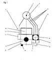
- FIG. 1 is shown purely schematically the plan view of an inventive blowing station of a stretch blow molding machine.
- the rotary distributor 2 is arranged concentrically, resp. executed.
- the rotary distributor 2 may be, for example, a motor-driven, rotating about the axis of rotation 1 blowing wheel.
- a blowing station 3 is arranged radially spaced from the axis of rotation 1, with a machine stand 12 which is arranged parallel to the vertical axis 1. At this Machine stand 12, the components of the blowing station 3 are arranged.
- the blowing cylinder 5 is arranged in a rectangular cross-section cylinder support 13 along its longitudinal axis A slidably. In this way, the blowing cylinder 5 can be moved parallel to the longitudinal axis A and thus also parallel to the axis of rotation 1 of the stretch blow molding machine in accordance with the direction indicated by the arrow H.
- the blowing block 7 is advantageously arranged to the right of the blowing cylinder 5, for example by attachment to the cylinder support 13.
- the valves necessary for the two-stage blowing process are arranged together, as is known for example from the prior art.
- a Vorblasventil, a main blow valve and a economy valve are arranged directly above one another in the blowing block 7.
- valves are advantageously arranged one above the other in a direction parallel to the axis of rotation 1 extending axis.
- the control resp. Assigned to each of these valves.
- Pilot valves 8 are now radially from the axis of rotation 1 to Outside pointing also arranged on Blasblock 7. Thus these control or pilot valves 8 are easily visible and accessible from the outside of the stretch blow molding machine.
- the blow-off valve 9 is advantageously arranged above the blow-block 7 in the extension of the blow-block axis B. From the blow-off valve 9, a silencer 10 also continues to extend in an extension of the blow-block axis B upwards, parallel to the axis of rotation 1. For this purpose, a blow-off valve 9 in a coaxial design is advantageously used.
- the discharged to the environment exhaust air from the blowing cylinder 5, respectively.
- the Blasstation 3 are discharged to save space, without that in the radial direction from the center of rotation 1 ago this would require additional space. That the necessary base area for the stretch blow molding machine is not affected by the muffler 10 and the discharge lines.
- the muffler 10 could also be formed radially inward in the direction of the rotary distributor 2, and the discharge line in the region of the rotary distributor are guided centrally upwards.
- a 5/2-way control valve 11 is also arranged laterally of the blowing cylinder 5 on the left side, that the control of the lifting movement of the blowing cylinder 5 is used.
- the supply line 11 'of this control valve 11 can also be carried out radially to the rear in the direction of the rotary distributor, whereby access from the front of the control valve 11 remains unobstructed.
- the actual control lines from Control valve 11 to the blowing cylinder 5 are advantageously arranged integrated in the cylinder support 13.
- control or display elements such as control buttons or status lamps, or for example exhaust throttles 14 are advantageously arranged on the front side of the cylinder support 13 and are therefore also easily visible and accessible easily and without hindrance.
- the entire layout is on the one hand very compact and space-saving, resulting in small footprints of the stretch blow molding machines, and on the other hand provides optimum accessibility from the front, i. radially from the outside in the direction of the axis of rotation 1.
- the individual components are both well visible, easy to use and in the case of repairs, maintenance or replacement optimally accessible without the blowing station 3 this would have to be partially or completely disassembled.
Landscapes
- Engineering & Computer Science (AREA)
- Manufacturing & Machinery (AREA)
- Mechanical Engineering (AREA)
- Blow-Moulding Or Thermoforming Of Plastics Or The Like (AREA)
Claims (11)
- Poste de soufflage pour machine d'étirage et de soufflage comprenant un axe de rotation vertical central (1) et un distributeur rotatif (2) placé au niveau de l'axe de rotation (1) pour de l'air comprimé et du courant, comprenant chacun au moins un corps de moule (4) pour recevoir des préformes de bouteille, un cylindre de soufflage (5) disposé de manière mobile par rapport au corps de moule (4), des valves disposées sur le cylindre de soufflage (5) pour réguler l'arrivée et l'évacuation de l'air comprimé, et des raccords pour des conduits (6) pour relier les valves au distributeur rotatif (2), sachant que le cylindre de soufflage (5) est disposé dans le poste de soufflage (3) verticalement au-dessus du corps de moule (4) en pouvant être déplacé le long de son axe longitudinal (A) parallèlement à l'axe de rotation (1) de la machine d'étirage et de soufflage, et les valves sont placées dans un bloc de soufflage (7) unique, caractérisé en ce que le bloc de soufflage (7) est disposé sur le côté du cylindre de soufflage (5) sur le poste de soufflage (3).
- Poste de soufflage selon la revendication 1, caractérisé en ce que des valves de commande respectivement de pilotage (8) pour commander les valves sont disposées sur le bloc de soufflage (7), de préférence respectivement l'une sur l'autre parallèlement à l'axe longitudinal (A) du bloc de soufflage (7) en pointant conjointement vers la face avant.
- Poste de soufflage selon la revendication 1 ou 2, caractérisé en ce que des raccords pour des conduits (6) sont placés depuis le distributeur rotatif (2) respectivement sur la face arrière du bloc de soufflage (7).
- Poste de soufflage selon l'une des revendications 1 à 3, caractérisé en ce qu'une valve de purge (9) est disposée sur le côté supérieur du bloc de soufflage (7) en étant dirigée parallèlement à l'axe longitudinal (A).
- Poste de soufflage selon la revendication 4, caractérisé en ce qu'un silencieux d'échappement (10) est placé axialement au-dessus de la valve de purge (9).
- Poste de soufflage selon la revendication 5, caractérisé en ce que le silencieux d'échappement (10) présente un canal de purge comprenant un dispositif de purge s'étendant essentiellement parallèlement à l'axe longitudinal (A).
- Poste de soufflage selon la revendication 5, caractérisé en ce que le silencieux d'échappement (10) présente un canal d'évacuation comprenant un dispositif de purge s'étendant essentiellement verticalement à l'axe longitudinal (A), de préférence verticalement en pointant vers l'extérieur depuis la face arrière du poste de soufflage (3).
- Poste de soufflage selon l'une des revendications 1 à 7, caractérisé en ce qu'une valve de commande (11) pour commander le mouvement de déplacement respectivement de course du cylindre de soufflage (5) est disposée également sur le côté du cylindre de soufflage (5), de préférence sur le côté du cylindre de soufflage (5) faisant face au bloc de soufflage (7).
- Poste de soufflage selon l'une des revendications 1 à 8, caractérisé en ce que tous les éléments opérationnels et fonctionnels sont disposés sur le, respectivement, autour du cylindre de soufflage (5) en pointant vers l'extérieur en direction de la face avant du poste de soufflage (3).
- Poste de soufflage selon la revendication 9, caractérisé en ce que tous les éléments opérationnels et fonctionnels sont disposés dans un boîtier commun, lequel est disposé sur le, respectivement, autour du cylindre de soufflage (5), de préférence sur un porte-cylindre (13).
- Machine d'étirage et de soufflage comprenant un axe de rotation (1) vertical central et un distributeur rotatif (2) placé au niveau de l'axe de rotation (1) pour de l'air comprimé et du courant, caractérisé en ce que les postes de soufflage (3) selon l'une des revendications 1 à 10 sont disposés radialement autour de l'axe de rotation (1), sachant que le côté extérieur des postes de soufflage (3) est disposé en pointant vers l'extérieur, radialement depuis l'axe de rotation (1).
Priority Applications (1)
| Application Number | Priority Date | Filing Date | Title |
|---|---|---|---|
| EP09075332A EP2133190A2 (fr) | 2006-03-20 | 2006-03-20 | Station de soufflage pour machines de soufflage-étirage |
Applications Claiming Priority (1)
| Application Number | Priority Date | Filing Date | Title |
|---|---|---|---|
| PCT/CH2006/000162 WO2007107016A1 (fr) | 2006-03-20 | 2006-03-20 | Poste de soufflage pour machine de soufflage-etirage |
Related Child Applications (2)
| Application Number | Title | Priority Date | Filing Date |
|---|---|---|---|
| EP09075332A Division EP2133190A2 (fr) | 2006-03-20 | 2006-03-20 | Station de soufflage pour machines de soufflage-étirage |
| EP09075332.8 Division-Into | 2009-07-23 |
Publications (2)
| Publication Number | Publication Date |
|---|---|
| EP1996385A1 EP1996385A1 (fr) | 2008-12-03 |
| EP1996385B1 true EP1996385B1 (fr) | 2011-10-05 |
Family
ID=37499317
Family Applications (2)
| Application Number | Title | Priority Date | Filing Date |
|---|---|---|---|
| EP06705402A Expired - Lifetime EP1996385B1 (fr) | 2006-03-20 | 2006-03-20 | Poste de soufflage pour machine de soufflage-etirage |
| EP09075332A Withdrawn EP2133190A2 (fr) | 2006-03-20 | 2006-03-20 | Station de soufflage pour machines de soufflage-étirage |
Family Applications After (1)
| Application Number | Title | Priority Date | Filing Date |
|---|---|---|---|
| EP09075332A Withdrawn EP2133190A2 (fr) | 2006-03-20 | 2006-03-20 | Station de soufflage pour machines de soufflage-étirage |
Country Status (5)
| Country | Link |
|---|---|
| EP (2) | EP1996385B1 (fr) |
| CN (1) | CN101400502B (fr) |
| AT (1) | ATE527095T1 (fr) |
| TW (1) | TW200800571A (fr) |
| WO (1) | WO2007107016A1 (fr) |
Families Citing this family (4)
| Publication number | Priority date | Publication date | Assignee | Title |
|---|---|---|---|---|
| DE102008034241A1 (de) * | 2008-07-23 | 2010-01-28 | Krones Ag | Vorrichtung zum Expandieren von Kunststoffvorformlingen zu Behältnissen |
| DE102009020738A1 (de) | 2009-05-11 | 2010-11-25 | Krones Ag | Vorrichtung zum Blasformen von Kunststoffvorformlingen mit reduziertem Totvolumen |
| CN104191596A (zh) * | 2014-08-06 | 2014-12-10 | 昌盛达机械(浙江)有限公司 | 旋转吹瓶机的气分配器 |
| CN110744805A (zh) * | 2019-11-26 | 2020-02-04 | 江苏辉河包装机械有限公司 | 一种塑料瓶吹制设备 |
Family Cites Families (7)
| Publication number | Priority date | Publication date | Assignee | Title |
|---|---|---|---|---|
| DE20018500U1 (de) * | 2000-10-28 | 2001-12-13 | KRONES AG, 93073 Neutraubling | Blasmaschine |
| FR2827541B1 (fr) * | 2001-07-20 | 2005-07-01 | Technoplan Engineering S A | Dispositif de soufflage d'emballages |
| DE10355365A1 (de) * | 2003-11-25 | 2005-06-23 | Sig Technology Ltd. | Vorrichtung zur Blasformung von Behältern |
| DE102004008400A1 (de) * | 2004-02-20 | 2005-09-08 | Sig Technology Ltd. | Vorrichtung zur Bearbeitung von Werkstücken |
| CN2712609Y (zh) * | 2004-04-22 | 2005-07-27 | 全冠(福建)机械工业有限公司 | 吹瓶机的吹瓶回路整合装置 |
| FR2872081B1 (fr) * | 2004-06-28 | 2006-10-06 | Sidel Sas | Machine tournante a colonne tournante d'alimentation electrique et fluidique |
| DE102004041973B3 (de) * | 2004-08-31 | 2006-01-19 | Krones Ag | Luftrecycling im Blasformprozess |
-
2006
- 2006-03-20 EP EP06705402A patent/EP1996385B1/fr not_active Expired - Lifetime
- 2006-03-20 AT AT06705402T patent/ATE527095T1/de active
- 2006-03-20 EP EP09075332A patent/EP2133190A2/fr not_active Withdrawn
- 2006-03-20 CN CN2006800539218A patent/CN101400502B/zh not_active Expired - Fee Related
- 2006-03-20 WO PCT/CH2006/000162 patent/WO2007107016A1/fr not_active Ceased
-
2007
- 2007-02-05 TW TW096104106A patent/TW200800571A/zh unknown
Also Published As
| Publication number | Publication date |
|---|---|
| EP2133190A2 (fr) | 2009-12-16 |
| CN101400502B (zh) | 2012-07-04 |
| EP1996385A1 (fr) | 2008-12-03 |
| CN101400502A (zh) | 2009-04-01 |
| WO2007107016A1 (fr) | 2007-09-27 |
| ATE527095T1 (de) | 2011-10-15 |
| TW200800571A (en) | 2008-01-01 |
Similar Documents
| Publication | Publication Date | Title |
|---|---|---|
| EP1328396B1 (fr) | Machine de soufflage comportant des soupapes de commande de l'air de soufflage logees sur le dispositif de soufflage | |
| EP2253451B1 (fr) | Dispositif de moulage par soufflage de préformes en matière synthétique dotées d'un volume mort réduit et installation correspondante | |
| EP2358513B1 (fr) | Système de post-traitement et de transfert de préformes | |
| DE102007012779A1 (de) | Formkühlungssystem für IS-Maschine | |
| EP1974892A2 (fr) | Procédé destiné au moulage par soufflage | |
| DE102016103237B4 (de) | Thermoformwerkzeug zur Herstellung becherförmiger Gegenstände | |
| DE3316757C2 (fr) | ||
| EP3825097B1 (fr) | Dispositif de formage des préformes en matière plastique pour obtenir des récipients en matière plastique pourvu de soupape proportionnelle | |
| EP3109031A1 (fr) | Production de haute pression adiabatique | |
| EP2653290B1 (fr) | Machine de formage par soufflage avec refroidissement du sol dans une phase de stabilisation | |
| DE3130694A1 (de) | Glasformvorrichtung und insbesondere dafuer vorgesehene zufuehr-, muendungsring-, kolben-zylinder-, blaskopf- und uebergabevorrichtung | |
| EP2176053B1 (fr) | Dispositif de soufflage de récipients | |
| CH387280A (de) | Verfahren und Maschine zur Herstellung von hohlen Kunststoff-Formteilen | |
| EP3272498A1 (fr) | Moule de soufflage, machine de formage par soufflage et procédé de transformation de de préformes en matière plastique en récipients en matière plastique dotés d'une évacuation d'air | |
| EP2618986A2 (fr) | Procédé et dispositif de moulage par soufflage de récipients | |
| EP1996385B1 (fr) | Poste de soufflage pour machine de soufflage-etirage | |
| DE1202474B (de) | Maschine zum Formen von hohlen Gegenstaenden | |
| EP1660303B1 (fr) | Procede et dispositif de moulage par soufflage de recipients | |
| EP1520681B1 (fr) | Dispositif pour mouler par soufflage des corps creux en matière thermoplastique | |
| EP4201638B1 (fr) | Moule de soufflage permettant de former des préformes en matière plastique pour obtenir des récipients en matière plastique pourvus de sortie d'air, ainsi que partie de fond pour un moule de soufflage | |
| EP1535720B1 (fr) | Dispositif pour moulage par soufflage d' articles | |
| DE102022109817A1 (de) | Ventilblock | |
| DE102014102448B4 (de) | Vorrichtung und Verfahren zum Umformen, insbesondere Fließpressen, von metallischen Werkstücken | |
| WO2003022756A1 (fr) | Procede et station de finition pour le soufflage final d'un contenant en verre | |
| DE19851132A1 (de) | IS-Maschine |
Legal Events
| Date | Code | Title | Description |
|---|---|---|---|
| PUAI | Public reference made under article 153(3) epc to a published international application that has entered the european phase |
Free format text: ORIGINAL CODE: 0009012 |
|
| 17P | Request for examination filed |
Effective date: 20080903 |
|
| AK | Designated contracting states |
Kind code of ref document: A1 Designated state(s): AT BE BG CH CY CZ DE DK EE ES FI FR GB GR HU IE IS IT LI LT LU LV MC NL PL PT RO SE SI SK TR |
|
| 17Q | First examination report despatched |
Effective date: 20090212 |
|
| GRAP | Despatch of communication of intention to grant a patent |
Free format text: ORIGINAL CODE: EPIDOSNIGR1 |
|
| GRAS | Grant fee paid |
Free format text: ORIGINAL CODE: EPIDOSNIGR3 |
|
| GRAA | (expected) grant |
Free format text: ORIGINAL CODE: 0009210 |
|
| DAX | Request for extension of the european patent (deleted) | ||
| AK | Designated contracting states |
Kind code of ref document: B1 Designated state(s): AT BE BG CH CY CZ DE DK EE ES FI FR GB GR HU IE IS IT LI LT LU LV MC NL PL PT RO SE SI SK TR |
|
| REG | Reference to a national code |
Ref country code: GB Ref legal event code: FG4D Free format text: NOT ENGLISH |
|
| REG | Reference to a national code |
Ref country code: CH Ref legal event code: EP |
|
| REG | Reference to a national code |
Ref country code: IE Ref legal event code: FG4D |
|
| REG | Reference to a national code |
Ref country code: CH Ref legal event code: NV Representative=s name: R. A. EGLI & CO. PATENTANWAELTE |
|
| REG | Reference to a national code |
Ref country code: DE Ref legal event code: R096 Ref document number: 502006010327 Country of ref document: DE Effective date: 20111229 |
|
| REG | Reference to a national code |
Ref country code: NL Ref legal event code: VDEP Effective date: 20111005 |
|
| PG25 | Lapsed in a contracting state [announced via postgrant information from national office to epo] |
Ref country code: SI Free format text: LAPSE BECAUSE OF FAILURE TO SUBMIT A TRANSLATION OF THE DESCRIPTION OR TO PAY THE FEE WITHIN THE PRESCRIBED TIME-LIMIT Effective date: 20111005 |
|
| LTIE | Lt: invalidation of european patent or patent extension |
Effective date: 20111005 |
|
| PG25 | Lapsed in a contracting state [announced via postgrant information from national office to epo] |
Ref country code: LT Free format text: LAPSE BECAUSE OF FAILURE TO SUBMIT A TRANSLATION OF THE DESCRIPTION OR TO PAY THE FEE WITHIN THE PRESCRIBED TIME-LIMIT Effective date: 20111005 Ref country code: IS Free format text: LAPSE BECAUSE OF FAILURE TO SUBMIT A TRANSLATION OF THE DESCRIPTION OR TO PAY THE FEE WITHIN THE PRESCRIBED TIME-LIMIT Effective date: 20120205 |
|
| REG | Reference to a national code |
Ref country code: IE Ref legal event code: FD4D |
|
| PG25 | Lapsed in a contracting state [announced via postgrant information from national office to epo] |
Ref country code: NL Free format text: LAPSE BECAUSE OF FAILURE TO SUBMIT A TRANSLATION OF THE DESCRIPTION OR TO PAY THE FEE WITHIN THE PRESCRIBED TIME-LIMIT Effective date: 20111005 Ref country code: PT Free format text: LAPSE BECAUSE OF FAILURE TO SUBMIT A TRANSLATION OF THE DESCRIPTION OR TO PAY THE FEE WITHIN THE PRESCRIBED TIME-LIMIT Effective date: 20120206 Ref country code: LV Free format text: LAPSE BECAUSE OF FAILURE TO SUBMIT A TRANSLATION OF THE DESCRIPTION OR TO PAY THE FEE WITHIN THE PRESCRIBED TIME-LIMIT Effective date: 20111005 Ref country code: GR Free format text: LAPSE BECAUSE OF FAILURE TO SUBMIT A TRANSLATION OF THE DESCRIPTION OR TO PAY THE FEE WITHIN THE PRESCRIBED TIME-LIMIT Effective date: 20120106 Ref country code: SE Free format text: LAPSE BECAUSE OF FAILURE TO SUBMIT A TRANSLATION OF THE DESCRIPTION OR TO PAY THE FEE WITHIN THE PRESCRIBED TIME-LIMIT Effective date: 20111005 |
|
| PG25 | Lapsed in a contracting state [announced via postgrant information from national office to epo] |
Ref country code: CY Free format text: LAPSE BECAUSE OF FAILURE TO SUBMIT A TRANSLATION OF THE DESCRIPTION OR TO PAY THE FEE WITHIN THE PRESCRIBED TIME-LIMIT Effective date: 20111005 |
|
| PLBI | Opposition filed |
Free format text: ORIGINAL CODE: 0009260 |
|
| PG25 | Lapsed in a contracting state [announced via postgrant information from national office to epo] |
Ref country code: BG Free format text: LAPSE BECAUSE OF FAILURE TO SUBMIT A TRANSLATION OF THE DESCRIPTION OR TO PAY THE FEE WITHIN THE PRESCRIBED TIME-LIMIT Effective date: 20120105 Ref country code: EE Free format text: LAPSE BECAUSE OF FAILURE TO SUBMIT A TRANSLATION OF THE DESCRIPTION OR TO PAY THE FEE WITHIN THE PRESCRIBED TIME-LIMIT Effective date: 20111005 Ref country code: SK Free format text: LAPSE BECAUSE OF FAILURE TO SUBMIT A TRANSLATION OF THE DESCRIPTION OR TO PAY THE FEE WITHIN THE PRESCRIBED TIME-LIMIT Effective date: 20111005 Ref country code: DK Free format text: LAPSE BECAUSE OF FAILURE TO SUBMIT A TRANSLATION OF THE DESCRIPTION OR TO PAY THE FEE WITHIN THE PRESCRIBED TIME-LIMIT Effective date: 20111005 Ref country code: IE Free format text: LAPSE BECAUSE OF FAILURE TO SUBMIT A TRANSLATION OF THE DESCRIPTION OR TO PAY THE FEE WITHIN THE PRESCRIBED TIME-LIMIT Effective date: 20111005 |
|
| 26 | Opposition filed |
Opponent name: SIDEL PARTICIPATIONS, S.A.S. Effective date: 20120702 Opponent name: FESTO AG & CO. KG Effective date: 20120705 |
|
| PLAX | Notice of opposition and request to file observation + time limit sent |
Free format text: ORIGINAL CODE: EPIDOSNOBS2 |
|
| PG25 | Lapsed in a contracting state [announced via postgrant information from national office to epo] |
Ref country code: RO Free format text: LAPSE BECAUSE OF FAILURE TO SUBMIT A TRANSLATION OF THE DESCRIPTION OR TO PAY THE FEE WITHIN THE PRESCRIBED TIME-LIMIT Effective date: 20111005 Ref country code: PL Free format text: LAPSE BECAUSE OF FAILURE TO SUBMIT A TRANSLATION OF THE DESCRIPTION OR TO PAY THE FEE WITHIN THE PRESCRIBED TIME-LIMIT Effective date: 20111005 |
|
| REG | Reference to a national code |
Ref country code: DE Ref legal event code: R026 Ref document number: 502006010327 Country of ref document: DE Effective date: 20120702 |
|
| BERE | Be: lapsed |
Owner name: EUGEN SEITZ A.G. Effective date: 20120331 |
|
| PG25 | Lapsed in a contracting state [announced via postgrant information from national office to epo] |
Ref country code: MC Free format text: LAPSE BECAUSE OF NON-PAYMENT OF DUE FEES Effective date: 20120331 |
|
| PG25 | Lapsed in a contracting state [announced via postgrant information from national office to epo] |
Ref country code: BE Free format text: LAPSE BECAUSE OF NON-PAYMENT OF DUE FEES Effective date: 20120331 |
|
| PG25 | Lapsed in a contracting state [announced via postgrant information from national office to epo] |
Ref country code: ES Free format text: LAPSE BECAUSE OF FAILURE TO SUBMIT A TRANSLATION OF THE DESCRIPTION OR TO PAY THE FEE WITHIN THE PRESCRIBED TIME-LIMIT Effective date: 20120116 |
|
| REG | Reference to a national code |
Ref country code: AT Ref legal event code: MM01 Ref document number: 527095 Country of ref document: AT Kind code of ref document: T Effective date: 20120320 |
|
| PG25 | Lapsed in a contracting state [announced via postgrant information from national office to epo] |
Ref country code: FI Free format text: LAPSE BECAUSE OF FAILURE TO SUBMIT A TRANSLATION OF THE DESCRIPTION OR TO PAY THE FEE WITHIN THE PRESCRIBED TIME-LIMIT Effective date: 20111005 |
|
| PG25 | Lapsed in a contracting state [announced via postgrant information from national office to epo] |
Ref country code: AT Free format text: LAPSE BECAUSE OF NON-PAYMENT OF DUE FEES Effective date: 20120320 |
|
| PLBP | Opposition withdrawn |
Free format text: ORIGINAL CODE: 0009264 |
|
| PG25 | Lapsed in a contracting state [announced via postgrant information from national office to epo] |
Ref country code: TR Free format text: LAPSE BECAUSE OF FAILURE TO SUBMIT A TRANSLATION OF THE DESCRIPTION OR TO PAY THE FEE WITHIN THE PRESCRIBED TIME-LIMIT Effective date: 20111005 |
|
| PG25 | Lapsed in a contracting state [announced via postgrant information from national office to epo] |
Ref country code: LU Free format text: LAPSE BECAUSE OF NON-PAYMENT OF DUE FEES Effective date: 20120320 |
|
| PG25 | Lapsed in a contracting state [announced via postgrant information from national office to epo] |
Ref country code: HU Free format text: LAPSE BECAUSE OF FAILURE TO SUBMIT A TRANSLATION OF THE DESCRIPTION OR TO PAY THE FEE WITHIN THE PRESCRIBED TIME-LIMIT Effective date: 20060320 |
|
| PLBP | Opposition withdrawn |
Free format text: ORIGINAL CODE: 0009264 |
|
| PLBD | Termination of opposition procedure: decision despatched |
Free format text: ORIGINAL CODE: EPIDOSNOPC1 |
|
| PLAB | Opposition data, opponent's data or that of the opponent's representative modified |
Free format text: ORIGINAL CODE: 0009299OPPO |
|
| PLBM | Termination of opposition procedure: date of legal effect published |
Free format text: ORIGINAL CODE: 0009276 |
|
| STAA | Information on the status of an ep patent application or granted ep patent |
Free format text: STATUS: OPPOSITION PROCEDURE CLOSED |
|
| 27C | Opposition proceedings terminated |
Effective date: 20150220 |
|
| REG | Reference to a national code |
Ref country code: FR Ref legal event code: PLFP Year of fee payment: 11 |
|
| REG | Reference to a national code |
Ref country code: FR Ref legal event code: PLFP Year of fee payment: 12 |
|
| REG | Reference to a national code |
Ref country code: CH Ref legal event code: NV Representative=s name: ISLER AND PEDRAZZINI AG, CH |
|
| REG | Reference to a national code |
Ref country code: FR Ref legal event code: PLFP Year of fee payment: 13 |
|
| PGFP | Annual fee paid to national office [announced via postgrant information from national office to epo] |
Ref country code: GB Payment date: 20200323 Year of fee payment: 15 |
|
| PGFP | Annual fee paid to national office [announced via postgrant information from national office to epo] |
Ref country code: CZ Payment date: 20200221 Year of fee payment: 15 |
|
| PG25 | Lapsed in a contracting state [announced via postgrant information from national office to epo] |
Ref country code: CZ Free format text: LAPSE BECAUSE OF NON-PAYMENT OF DUE FEES Effective date: 20210320 |
|
| GBPC | Gb: european patent ceased through non-payment of renewal fee |
Effective date: 20210320 |
|
| PG25 | Lapsed in a contracting state [announced via postgrant information from national office to epo] |
Ref country code: GB Free format text: LAPSE BECAUSE OF NON-PAYMENT OF DUE FEES Effective date: 20210320 |
|
| PGFP | Annual fee paid to national office [announced via postgrant information from national office to epo] |
Ref country code: DE Payment date: 20220322 Year of fee payment: 17 Ref country code: CH Payment date: 20220311 Year of fee payment: 17 |
|
| PGFP | Annual fee paid to national office [announced via postgrant information from national office to epo] |
Ref country code: IT Payment date: 20220323 Year of fee payment: 17 Ref country code: FR Payment date: 20220322 Year of fee payment: 17 |
|
| REG | Reference to a national code |
Ref country code: DE Ref legal event code: R119 Ref document number: 502006010327 Country of ref document: DE |
|
| REG | Reference to a national code |
Ref country code: CH Ref legal event code: PL |
|
| PG25 | Lapsed in a contracting state [announced via postgrant information from national office to epo] |
Ref country code: LI Free format text: LAPSE BECAUSE OF NON-PAYMENT OF DUE FEES Effective date: 20230331 Ref country code: FR Free format text: LAPSE BECAUSE OF NON-PAYMENT OF DUE FEES Effective date: 20230331 Ref country code: DE Free format text: LAPSE BECAUSE OF NON-PAYMENT OF DUE FEES Effective date: 20231003 Ref country code: CH Free format text: LAPSE BECAUSE OF NON-PAYMENT OF DUE FEES Effective date: 20230331 |
|
| PG25 | Lapsed in a contracting state [announced via postgrant information from national office to epo] |
Ref country code: IT Free format text: LAPSE BECAUSE OF NON-PAYMENT OF DUE FEES Effective date: 20230320 |