EP1996405B1 - Cartouche d'encre pour imprimantes - Google Patents
Cartouche d'encre pour imprimantes Download PDFInfo
- Publication number
- EP1996405B1 EP1996405B1 EP07745591A EP07745591A EP1996405B1 EP 1996405 B1 EP1996405 B1 EP 1996405B1 EP 07745591 A EP07745591 A EP 07745591A EP 07745591 A EP07745591 A EP 07745591A EP 1996405 B1 EP1996405 B1 EP 1996405B1
- Authority
- EP
- European Patent Office
- Prior art keywords
- ink
- chamber
- air
- filling
- printers
- Prior art date
- Legal status (The legal status is an assumption and is not a legal conclusion. Google has not performed a legal analysis and makes no representation as to the accuracy of the status listed.)
- Not-in-force
Links
- 238000007599 discharging Methods 0.000 claims abstract description 39
- 230000000903 blocking effect Effects 0.000 claims abstract description 12
- 230000001105 regulatory effect Effects 0.000 claims abstract description 11
- 230000001939 inductive effect Effects 0.000 claims abstract description 10
- 238000005192 partition Methods 0.000 claims description 9
- 238000002347 injection Methods 0.000 claims description 7
- 239000007924 injection Substances 0.000 claims description 7
- 230000002411 adverse Effects 0.000 claims description 5
- 238000012856 packing Methods 0.000 claims description 4
- 238000000034 method Methods 0.000 abstract description 6
- 230000002542 deteriorative effect Effects 0.000 description 2
- 238000004519 manufacturing process Methods 0.000 description 1
- 239000011159 matrix material Substances 0.000 description 1
- 239000000243 solution Substances 0.000 description 1
Images





Classifications
-
- B—PERFORMING OPERATIONS; TRANSPORTING
- B41—PRINTING; LINING MACHINES; TYPEWRITERS; STAMPS
- B41J—TYPEWRITERS; SELECTIVE PRINTING MECHANISMS, i.e. MECHANISMS PRINTING OTHERWISE THAN FROM A FORME; CORRECTION OF TYPOGRAPHICAL ERRORS
- B41J2/00—Typewriters or selective printing mechanisms characterised by the printing or marking process for which they are designed
- B41J2/005—Typewriters or selective printing mechanisms characterised by the printing or marking process for which they are designed characterised by bringing liquid or particles selectively into contact with a printing material
- B41J2/01—Ink jet
- B41J2/17—Ink jet characterised by ink handling
- B41J2/175—Ink supply systems ; Circuit parts therefor
- B41J2/17503—Ink cartridges
- B41J2/17506—Refilling of the cartridge
-
- B—PERFORMING OPERATIONS; TRANSPORTING
- B41—PRINTING; LINING MACHINES; TYPEWRITERS; STAMPS
- B41J—TYPEWRITERS; SELECTIVE PRINTING MECHANISMS, i.e. MECHANISMS PRINTING OTHERWISE THAN FROM A FORME; CORRECTION OF TYPOGRAPHICAL ERRORS
- B41J2/00—Typewriters or selective printing mechanisms characterised by the printing or marking process for which they are designed
- B41J2/005—Typewriters or selective printing mechanisms characterised by the printing or marking process for which they are designed characterised by bringing liquid or particles selectively into contact with a printing material
- B41J2/01—Ink jet
- B41J2/17—Ink jet characterised by ink handling
- B41J2/175—Ink supply systems ; Circuit parts therefor
- B41J2/17503—Ink cartridges
- B41J2/17513—Inner structure
-
- B—PERFORMING OPERATIONS; TRANSPORTING
- B41—PRINTING; LINING MACHINES; TYPEWRITERS; STAMPS
- B41J—TYPEWRITERS; SELECTIVE PRINTING MECHANISMS, i.e. MECHANISMS PRINTING OTHERWISE THAN FROM A FORME; CORRECTION OF TYPOGRAPHICAL ERRORS
- B41J2/00—Typewriters or selective printing mechanisms characterised by the printing or marking process for which they are designed
- B41J2/005—Typewriters or selective printing mechanisms characterised by the printing or marking process for which they are designed characterised by bringing liquid or particles selectively into contact with a printing material
- B41J2/01—Ink jet
- B41J2/17—Ink jet characterised by ink handling
- B41J2/175—Ink supply systems ; Circuit parts therefor
- B41J2/17503—Ink cartridges
- B41J2/1752—Mounting within the printer
-
- B—PERFORMING OPERATIONS; TRANSPORTING
- B41—PRINTING; LINING MACHINES; TYPEWRITERS; STAMPS
- B41J—TYPEWRITERS; SELECTIVE PRINTING MECHANISMS, i.e. MECHANISMS PRINTING OTHERWISE THAN FROM A FORME; CORRECTION OF TYPOGRAPHICAL ERRORS
- B41J2/00—Typewriters or selective printing mechanisms characterised by the printing or marking process for which they are designed
- B41J2/005—Typewriters or selective printing mechanisms characterised by the printing or marking process for which they are designed characterised by bringing liquid or particles selectively into contact with a printing material
- B41J2/01—Ink jet
- B41J2/17—Ink jet characterised by ink handling
- B41J2/175—Ink supply systems ; Circuit parts therefor
- B41J2/17503—Ink cartridges
- B41J2/17553—Outer structure
-
- B—PERFORMING OPERATIONS; TRANSPORTING
- B41—PRINTING; LINING MACHINES; TYPEWRITERS; STAMPS
- B41J—TYPEWRITERS; SELECTIVE PRINTING MECHANISMS, i.e. MECHANISMS PRINTING OTHERWISE THAN FROM A FORME; CORRECTION OF TYPOGRAPHICAL ERRORS
- B41J2/00—Typewriters or selective printing mechanisms characterised by the printing or marking process for which they are designed
- B41J2/005—Typewriters or selective printing mechanisms characterised by the printing or marking process for which they are designed characterised by bringing liquid or particles selectively into contact with a printing material
- B41J2/01—Ink jet
- B41J2/17—Ink jet characterised by ink handling
- B41J2/175—Ink supply systems ; Circuit parts therefor
- B41J2/17503—Ink cartridges
- B41J2/17556—Means for regulating the pressure in the cartridge
Definitions
- the present invention relates to ink cartridge for printer.
- printers are used as a device for outputting documents or pictures drawn up using computer on papers, and the printers include a dot matrix printer, an ink-jet printer and a laser beam printer;
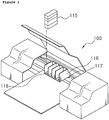
- the ink-jet printer (100) as shown in Fig. 1 , is provided with a cartridge deliverer 116 movably installed in an inside of the printer (100), and the cartridge deliverer (116) has a space into which an ink-cartridge (115) is removably mounted, a needle 118 sucking in ink filled in the ink-cartridge (115) and a head (117) injecting the ink transferred through the needle.
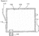
- the ink-cartridge has a predetermined size in order to be installed in the printer and provided with a body (110) formed with an accommodating part (130) therein and a fixing arm (113) extended from a side surface of the body (110) for fixing the body to the cartridge deliverer (116) of the printer.
- a packing member (205) is installed inside the ink discharging portion(140) to prevent the ink from flowing out by combining with the ink suction needle (118).
- a through hole (111) is formed to supply exterior air inside the body (110).
- the previous ink cartridges have the sponge (133), where the ink is impregnated, inside the body (110), so there are some problems that the space, where the ink is charged, is reduced, and the manufacturing cost becomes high by the process of installing the sponge (133) in the body (110).
- EP 1199178 discloses an ink cartridge according to the preamble of claim 1.
- the present invention is for solving the problems mentioned above and aims to provide the ink cartridge for printers that can expand the space where the ink is filled, and maintain pressure inside the ink cartridge, and also offset the pressure increase inside the cartridge by forming a pressure controller on one surface of the outer surface of the cartridge body where the ink is filled, in order to prevent the ink from flowing out or the printing quality from deteriorating due to temperature change an inside or an outside of the cartridge.
- the present invention aims to provide the ink cartridge for printers in which the ink can be filled in the adverse direction that the ink is discharged, so that the air remaining inside the cartridge can be completely removed.
- an ink cartridge for printers is provided and is defined in claim 1.
- the pressure regulating part here, is communicated by the filling chamber and at least communicate. It forms some space by the blocking film and reacts flexibly to pressure change of inner and outer part of the cartridge.
- the present invention further comprises a bubble collector in the upper part of the ink transferring channel.
- the present invention more comprises at least one partition that divides the filling chamber into a plurality of chambers.
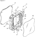
- Figure 3 to Figure 5 show the ink cartridge of Example 1 according to the present invention
- Figure 3 is an exploded perspective view
- Figure 4 is a cross-sectional view
- Figure 5 is a rear view.
- the present invention is An ink cartridge for printers comprising a body(10)formed in a predetermined shape and having a filling hole (11) on one surface of the body (10), a filling chamber (30) where ink is filled inside the body (10), a discharging chamber (31) connected to the filling chamber (30), an ink discharging port (40) connected to the discharging chamber (31) through the medium of an ink transferring channel (43), an air chamber (32) connected to the filling chamber (30) to supply air through the medium of an air transferring channel (55), an air suction valve (50) installed in the air chamber (32), an air inducing channel (56) that induces exterior air into the air suction valve (50), a blocking film (60) attached onto one surface of the body (10), and a cover(70) installed on another surface of the body(10), and a pressure regulating part (80) on one surface of outer body (10), which communicates with the filling chamber (30).
- the inside of the body (10) has some space for specific quantity of the ink to be filled and its size and form can be changed depending on the kind of printers.
- a fixing arm is made to fixate the cartridge in the head installed in printers.
- the space located on one side of outer surface of the body (10) is communicated with the filling chamber (30) through at least communicating hole (90) and sealed by the blocking film (60) to form the pressure regulating part (80).
- the pressure regulating part (80) plays a role in offsetting the pressure difference between inside and outside of the cartridge, which is caused by exterior temperature change. If excessive positive pressure or negative pressure is caused inside the cartridge due to exterior temperature change, the ink may flow through the ink discharging port (40) or contrarily, the ink may not be well discharged.
- the blocking film (60) which has elastic attached to the communicating hole (90) of the pressure regulating part (80), reacts to the pressure difference between inside and outside of the cartridge and flexibly expands or contracts and then naturally offsets the pressure difference and makes a balance, so that adequate quantity of the ink can be discharged through the ink discharging port (40).
- a discharging chamber (31) connected to the filling chamber (30) is made.
- ink discharging (40) In the lower side of the body (10), there is an ink discharging (40) that discharges the ink to the exterior. Inside the ink discharging (40), a packing member (41) is installed to prevent the ink from flowing out by combining with the ink suction needle.
- the ink discharging port (40), here, is connected to the discharging chamber (31) through the medium of an ink transferring channel (43), which is formed on one surface of outer body (10). It is desirable that the upper part of the ink transferring channel (43) should be formed near the upper part of the filling chamber (30), which makes the ink move only by suction power and prevents the ink from being excessively discharged.
- an air chamber (32) is formed inside the body (10) and the air chamber and the filling chamber (30) are connected to each other through the medium of an air transferring channel (55).
- an air suction valve (50) is installed in air chamber (32).
- the air suction valve (50) it is desirable that a check valve opening to the single direction only should be installed for exterior air to come in and for interior ink not to be discharged. That is, the air suction valve (50) has a plurality of ribs (51) on the side of the air chamber (32); in the empty central space of the ribs (51), the air suction valve (29) is installed, which has tack-formed tips.
- an air inducing hole (56) is formed to induce exterior air toward the air suction valve (50). It is desirable that the upper part of the air inducing channel (56) should be formed near the upper part of the filling chamber (30). The part of the air inducing channel(56) passes through the upper side of the body (10).
- a flexible blocking film (60) is installed to block the side of the ink moving channel(43) and the air inducing channel (56).
- a cover (70) is installed to block the filling chamber (30), the discharging chamber (31), and the air chamber (32).
- the ink that moves to the discharging chamber (31) through the filling chamber (30) goes toward the ink discharging port (40) along the ink transferring channel (43) by the electric sign transmitted from the printer.
- the ink cartridge becomes to have lower pressure inside while the ink is being discharged due to continuous printing work, which makes the air suction valve (29) installed in the air chamber (32) becomes open and lets the air in to the ink cartridge through the air inducing channel (56), so the ink cartridge maintain the pressure uniformly.
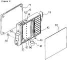
- FIG 6 is an exploded perspective view showing the ink cartridge of Example 2 according to the present invention.
- a bubble collector 44
- the bubble collector (44) is formed in the ink transferring channel (43) connected to the ink discharging port (40), which discharges the ink.
- the bubble collector Even when there are just a few bubbles mixed in the ink from the filling chamber (30), they pass through the bubble collector (44) and they are naturally separated in the upper part of the bubble collector (44) due to density difference, so pure ink without bubbles can be supplied to the ink discharging channel (40).
- Figure 7 is a cross-sectional view of the ink cartridge of Example 3 according to the present invention. From the ink cartridge shown in Figure 3 to 5 above, the filling chamber (30) is divided by the partition (20), which has a connecting hole(21) so that each filling chamber (30) can be communicated.
- At least one partition (20) should be installed horizontally to form a plurality of filling chambers (30). Since the filling chamber (30) is divided into a plurality ones by the partition (20), when the body (10) moves with the head, the movement of the ink filled in the filling chamber (30) is minimized, which prevents fine bubbles from forming in the ink. Also, by the ink movement, the inner body (10) of the ink cartridge becomes to have negative pressure, which prevents the ink filled in the ink suction needle or head from flowing backward.
- Figure 8 to 10 show the ink cartridge of Example 4, which has different forms and sizes respectively;
- Figure 8 is an exploded perspective view,
- Figure 9 is a cross-sectional view, and
- Figure 10 is a rear view. As long as they are in accord with the idea of the present invention, they can be applied to cartridges with various sizes and forms.
- the ink cartridge of other examples according to the present invention has the different size of the body (10), whose upper side has a filling hole (11) to charge the ink. After the ink is filled, the filling hole (11) is blocked by a rubber stopper (12). And on the surface of outer body (10), a fixing arm (13) is formed to generate fixing power when combined with the head installed in printers.
- the surface of outer body (10) is also connected to the filling chamber (30) through at least one communicating hole (90).
- the blocking film (60) which is welded to the outer wall and elastic, a pressure regulating part (80) is formed, taking some space.
- the inner space of the body (10) is divided into a plurality filling chambers (30) by the partition (20), which has the connecting hole (21) to enable each filling chamber (30) to be connected.
- the detailed description of the component is the same as above, so it will be omitted.
- FIG 11 is an exploded perspective view showing the ink cartridge of Example 5 according to the present invention.
- the present invention comprising a body(10)formed in a predetermined shape and having a filling hole (11) on one surface of the body (10), a filling chamber (30) where ink is filled inside the body (10), a discharging chamber (31) connected to the filling chamber (30), an ink discharging port (40) connected to the discharging chamber (31) through the medium of an ink transferring channel (43), an air chamber (32) connected to the filling chamber (30) to supply air through the medium of an air transferring channel (55), an air suction valve (50) installed in the air chamber (32), an air inducing channel (56) that induces exterior air into the air suction valve (50), a blocking film (60) attached onto one surface of the body (10), and a cover(70) installed on another surface of the body(10), and a pressure regulating part (80) on one surface of outer body (10), which communicates with the filling chamber (30), and the filling
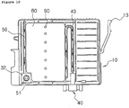
- Figure 12 is a view showing the ink filling method and the ink flow according to the present invention.
- the ink filling method of Figure 12 is as follows.
- the ink When the ink is filled with the filling hole (11), it firstly moves to the ink injection path (93) through the open hole in upper part of the ink injection path (93), which is communicated with the filling hole (11). Then, it goes along the ink transferring channel (43) to the discharging chamber (31) through the open hole in lower part of the ink injection path (93). The ink, now in the discharging chamber (31), moves to the filling chamber (30) and fills it. Using such ink filling method, the remaining air inside the cartridge can be completely removed, by filling the ink in the adverse direction that the ink is discharged when printing.
- the present invention can provide the ink cartridge for printers that can expand the space where the ink is filled, and maintain pressure inside the ink cartridge, and also offset the pressure increase inside the cartridge by forming a pressure controller on one surface of the outer surface of the cartridge body where the ink is filled, in order to prevent the ink from flowing out or the printing quality from deteriorating due to temperature change inside or outside of the cartridge.
- the ink cartridge of the present invention improves printing quality by collecting air bubbles, which is made by ink movement, in separate space and completely removing the bubbles that remains in the discharging route of ink.
- the present invention can provide the ink cartridge for printers in which the ink is filled in the adverse direction that the ink is discharged, so that the air remaining inside the cartridge can be completely removed.
Landscapes
- Ink Jet (AREA)
Claims (8)
- Cartouche d'encre pour imprimantes comprenant un corps (10) formé dans une forme prédéterminée et comportant un orifice de remplissage (11) sur une surface du corps (10),
une chambre de remplissage (30) où l'encre remplit l'intérieur du corps (10),
une chambre d'évacuation (31) formée dans le corps (10) et connectée à la chambre de remplissage (30),
une lumière d'évacuation d'encre (40) connectée à la chambre d'évacuation (31) via un canal de transfert d'encre (43) formé dans le corps (10),
une chambre à air (32) raccordée à la chambre de remplissage (30) via un canal de transfert d'air (55) afin d'alimenter la chambre de remplissage (30) en air,
un clapet d'aspiration d'air (50) installé dans la chambre à air (32),
un canal d'admission d'air (56) qui admet de l'air extérieur dans le clapet d'aspiration d'air (50),
un capot (70) installé sur une surface latérale du corps (10)
caractérisée par un film de blocage (60) qui est élastique et fixé sur une autre surface latérale du corps (10) et réagit à une différence de pression entre l'intérieur et l'extérieur de la cartouche d'encre et se dilate ou se contracte de façon flexible puis compense naturellement la différence de pression et établit un équilibre,
et une partie de régulation de pression (80) communiquant avec la chambre de remplissage (30) et définie par le corps (10) et le film de blocage (60) afin de former un espace prédéterminé, dans laquelle le capot est disposé sur une surface latérale opposée à la surface latérale comportant le film de blocage (60) de sorte que le capot bloque la chambre de remplissage (30) et la chambre d'évacuation (31). - Cartouche d'encre pour imprimantes selon la revendication 1, dans laquelle l'orifice de remplissage (11) est raccordé à la lumière d'évacuation d'encre (40) et au canal de transfert d'encre (43) via un chemin d'injection d'encre (93).
- Cartouche d'encre pour imprimantes selon la revendication 1 ou 2, dans laquelle la partie de régulation de pression (80) est mise en communication avec la chambre de remplissage (30) via au moins un orifice de communication (90).
- Cartouche d'encre pour imprimantes selon la revendication 1 ou 2, dans laquelle la cartouche d'encre comprend en outre un collecteur de bulle (44) dans la partie supérieure du canal de transfert d'encre (43).
- Cartouche d'encre pour imprimantes selon la revendication 1 ou 2, dans laquelle la chambre de remplissage (30) est divisée en une pluralité de chambres par au moins une cloison (20) qui comporte un orifice de raccordement (21).
- Cartouche d'encre pour imprimantes selon la revendication 1 ou 2, dans laquelle un organe de garnissage (41) est installé à l'intérieur de la lumière d'évacuation d'encre (40).
- Cartouche d'encre pour imprimantes selon la revendication 1 ou 2, dans laquelle le clapet d'aspiration d'air (50), qui ouvre et ferme sélectivement la chambre à air (32), est un clapet anti-retour qui est installé élastiquement afin de s'ouvrir uniquement dans cette seule direction.
- Cartouche d'encre pour imprimantes selon la revendication 1, dans laquelle l'orifice de remplissage (11) est raccordé à la lumière d'évacuation d'encre (40) et au canal de transfert d'encre (43) via un chemin d'injection d'encre (94) et l'encre est chargée dans la direction inverse de celle dans laquelle l'encre est évacuée lors de l'impression.
Applications Claiming Priority (3)
| Application Number | Priority Date | Filing Date | Title |
|---|---|---|---|
| KR20060025095 | 2006-03-18 | ||
| KR1020070026343A KR100855544B1 (ko) | 2006-03-18 | 2007-03-16 | 프린터용 잉크 카트리지 및 잉크충전방법 |
| PCT/KR2007/001316 WO2007108620A1 (fr) | 2006-03-18 | 2007-03-17 | Cartouche d'encre pour imprimantes et procédé de remplissage d'encre |
Publications (3)
| Publication Number | Publication Date |
|---|---|
| EP1996405A1 EP1996405A1 (fr) | 2008-12-03 |
| EP1996405A4 EP1996405A4 (fr) | 2009-12-30 |
| EP1996405B1 true EP1996405B1 (fr) | 2012-04-25 |
Family
ID=38688393
Family Applications (1)
| Application Number | Title | Priority Date | Filing Date |
|---|---|---|---|
| EP07745591A Not-in-force EP1996405B1 (fr) | 2006-03-18 | 2007-03-17 | Cartouche d'encre pour imprimantes |
Country Status (7)
| Country | Link |
|---|---|
| US (1) | US7997708B2 (fr) |
| EP (1) | EP1996405B1 (fr) |
| KR (1) | KR100855544B1 (fr) |
| CN (1) | CN101356059B (fr) |
| AT (1) | ATE554934T1 (fr) |
| RU (1) | RU2373068C1 (fr) |
| WO (1) | WO2007108620A1 (fr) |
Families Citing this family (14)
| Publication number | Priority date | Publication date | Assignee | Title |
|---|---|---|---|---|
| JP5454398B2 (ja) * | 2010-07-15 | 2014-03-26 | セイコーエプソン株式会社 | 液体収容容器、タンクユニット、および、液体噴射システム |
| KR101195050B1 (ko) | 2010-08-11 | 2012-11-01 | 김진홍 | 카트리지방식의 프린터 잉크 연속공급장치 |
| KR101248850B1 (ko) * | 2011-01-20 | 2013-04-01 | 전문배 | 프린터의 잉크공급장치 |
| JP2012210729A (ja) | 2011-03-30 | 2012-11-01 | Brother Industries Ltd | インクカートリッジ |
| JP2012210730A (ja) * | 2011-03-30 | 2012-11-01 | Brother Industries Ltd | インクカートリッジ |
| JP2012210726A (ja) | 2011-03-30 | 2012-11-01 | Brother Industries Ltd | インクカートリッジ |
| RU2647099C2 (ru) | 2012-08-10 | 2018-03-13 | Сейко Эпсон Корпорейшн | Контейнер для жидкости, потребляющее жидкость устройство, система подачи жидкости и блок контейнеров для жидкости |
| US9022539B2 (en) * | 2012-12-18 | 2015-05-05 | Brother Kogyo Kabushiki Kaisha | Ink cartridge provided with air communication portion |
| KR101627338B1 (ko) * | 2014-10-01 | 2016-06-07 | 김동민 | 잉크젯프린터용 잉크공급탱크 |
| JP6752569B2 (ja) * | 2015-10-30 | 2020-09-09 | キヤノン株式会社 | 記録装置 |
| JP6932899B2 (ja) * | 2016-03-31 | 2021-09-08 | ブラザー工業株式会社 | タンク |
| JP6274259B2 (ja) * | 2016-06-23 | 2018-02-07 | セイコーエプソン株式会社 | 液体収容体 |
| JP6838344B2 (ja) * | 2016-10-12 | 2021-03-03 | セイコーエプソン株式会社 | 液体収容体 |
| JP7172297B2 (ja) * | 2018-08-31 | 2022-11-16 | セイコーエプソン株式会社 | インクジェットプリンター |
Family Cites Families (20)
| Publication number | Priority date | Publication date | Assignee | Title |
|---|---|---|---|---|
| US5984463A (en) * | 1992-03-18 | 1999-11-16 | Hewlett-Packard Company | Two material frame having dissimilar properties for thermal ink-jet cartridge |
| US6000791A (en) | 1992-12-23 | 1999-12-14 | Hewlett-Packard Company | Printer having a removable print cartridge with handle incorporating an ink inlet value |
| US6243117B1 (en) * | 1995-05-12 | 2001-06-05 | Lexmark International, Inc. | Print head cartridge and method of making a print head cartridge by one-shot injection molding |
| US5988802A (en) * | 1996-08-30 | 1999-11-23 | Hewlett-Packard Company | Off-axis ink supply with pressurized ink tube for preventing air ingestion |
| JP3685262B2 (ja) * | 2000-10-20 | 2005-08-17 | セイコーエプソン株式会社 | インクジェット記録装置用インクカートリッジ |
| KR100487976B1 (ko) | 2000-10-20 | 2005-05-10 | 세이코 엡슨 가부시키가이샤 | 잉크젯 기록 장치용 잉크 카트리지 |
| TW533135B (en) * | 2001-01-08 | 2003-05-21 | Int United Technology Co Ltd | Ink container having pressure regulation device |
| KR100433529B1 (ko) | 2001-12-04 | 2004-05-31 | 삼성전자주식회사 | 압력조절모듈을 구비한 잉크 카트리지 |
| JP2003191489A (ja) * | 2001-12-27 | 2003-07-08 | Canon Inc | 液体収納容器 |
| US6783219B2 (en) | 2002-11-27 | 2004-08-31 | Monitek Electronics Limited | Ink cartridge |
| DE602004005668T2 (de) * | 2003-02-04 | 2007-12-27 | Brother Kogyo K.K., Nagoya | Luftblasenentfernung bei einem tintenstrahldrucker |
| US6817707B1 (en) | 2003-06-18 | 2004-11-16 | Lexmark International, Inc. | Pressure controlled ink jet printhead assembly |
| US7303271B2 (en) * | 2003-10-24 | 2007-12-04 | Brother Kogyo Kabushiki Kaisha | Ink jet printer |
| ATE358589T1 (de) * | 2003-12-04 | 2007-04-15 | Brother Ind Ltd | Tintenstrahldruckkopf und tintenstrahldrucker |
| JP4186828B2 (ja) * | 2004-01-30 | 2008-11-26 | ブラザー工業株式会社 | 液滴吐出装置及びその制御方法 |
| ATE540818T1 (de) * | 2004-05-12 | 2012-01-15 | Brother Ind Ltd | Farbstrahldrucker |
| JP4951911B2 (ja) * | 2005-09-26 | 2012-06-13 | ブラザー工業株式会社 | 画像記録装置の輸送方法 |
| ATE552117T1 (de) * | 2005-10-25 | 2012-04-15 | Inktec Co Ltd | Tintenpatrone für drucker |
| JP2007260947A (ja) * | 2006-03-27 | 2007-10-11 | Seiko Epson Corp | 液体供給装置及び液体噴射装置 |
| WO2007111475A1 (fr) * | 2006-03-28 | 2007-10-04 | Inktec Co., Ltd. | Cartouche d'encre pour imprimante |
-
2007
- 2007-03-16 KR KR1020070026343A patent/KR100855544B1/ko not_active Expired - Fee Related
- 2007-03-17 RU RU2008132508/12A patent/RU2373068C1/ru not_active IP Right Cessation
- 2007-03-17 WO PCT/KR2007/001316 patent/WO2007108620A1/fr not_active Ceased
- 2007-03-17 CN CN2007800013512A patent/CN101356059B/zh not_active Expired - Fee Related
- 2007-03-17 US US12/093,823 patent/US7997708B2/en not_active Expired - Fee Related
- 2007-03-17 AT AT07745591T patent/ATE554934T1/de active
- 2007-03-17 EP EP07745591A patent/EP1996405B1/fr not_active Not-in-force
Also Published As
| Publication number | Publication date |
|---|---|
| US7997708B2 (en) | 2011-08-16 |
| RU2373068C1 (ru) | 2009-11-20 |
| EP1996405A4 (fr) | 2009-12-30 |
| ATE554934T1 (de) | 2012-05-15 |
| EP1996405A1 (fr) | 2008-12-03 |
| KR20070094701A (ko) | 2007-09-21 |
| US20080278556A1 (en) | 2008-11-13 |
| KR100855544B1 (ko) | 2008-09-01 |
| CN101356059B (zh) | 2010-07-28 |
| WO2007108620A1 (fr) | 2007-09-27 |
| CN101356059A (zh) | 2009-01-28 |
Similar Documents
| Publication | Publication Date | Title |
|---|---|---|
| EP1996405B1 (fr) | Cartouche d'encre pour imprimantes | |
| CN102336061B (zh) | 液体收纳容器和液体喷射系统 | |
| CN109927414B (zh) | 打印装置和液体存储容器 | |
| KR100723563B1 (ko) | 액체 공급 시스템, 잉크 탱크, 잉크 공급 시스템, 및 잉크젯 기록 장치 | |
| NZ280044A (en) | Multi-chambered ink cartridge for ink jet printer | |
| JPH07108688A (ja) | インクタンクカートリッジおよび該インクタンクカートリッジが装着されるインクジェット装置 | |
| CN102336062B (zh) | 液体收纳容器、液体喷射系统以及液体供给系统 | |
| US20140125742A1 (en) | Ink Cartridge for Printer | |
| JP4725182B2 (ja) | 液体供給システムの製造方法及び液体供給システム | |
| EP1940627B1 (fr) | Cartouche d'encre pour imprimantes | |
| JPH0834122A (ja) | インクジェットカートリッジ及びそれを備えたインクジェット記録装置 | |
| CN101356060B (zh) | 用于打印机的墨盒 | |
| CN101374667B (zh) | 墨盒 | |
| KR100830667B1 (ko) | 프린터용 잉크 카트리지 및 잉크충전방법 | |
| JP4154619B2 (ja) | インクカートリッジ | |
| CN101312831B (zh) | 用于打印机的墨盒 | |
| JPH08300677A (ja) | インクジェット記録装置 | |
| JP4296444B2 (ja) | インクカートリッジのインク注入方法 | |
| JP2019084833A (ja) | 記録装置 | |
| JP2019162793A (ja) | インクカートリッジ、及び印刷装置 |
Legal Events
| Date | Code | Title | Description |
|---|---|---|---|
| PUAI | Public reference made under article 153(3) epc to a published international application that has entered the european phase |
Free format text: ORIGINAL CODE: 0009012 |
|
| 17P | Request for examination filed |
Effective date: 20080313 |
|
| AK | Designated contracting states |
Kind code of ref document: A1 Designated state(s): AT BE BG CH CY CZ DE DK EE ES FI FR GB GR HU IE IS IT LI LT LU LV MC MT NL PL PT RO SE SI SK TR |
|
| A4 | Supplementary search report drawn up and despatched |
Effective date: 20091130 |
|
| RIC1 | Information provided on ipc code assigned before grant |
Ipc: B41J 2/175 20060101AFI20071009BHEP Ipc: B41J 2/09 20060101ALI20091124BHEP |
|
| 17Q | First examination report despatched |
Effective date: 20100406 |
|
| GRAP | Despatch of communication of intention to grant a patent |
Free format text: ORIGINAL CODE: EPIDOSNIGR1 |
|
| RTI1 | Title (correction) |
Free format text: INK-CARTRIDGE FOR PRINTERS |
|
| DAX | Request for extension of the european patent (deleted) | ||
| GRAS | Grant fee paid |
Free format text: ORIGINAL CODE: EPIDOSNIGR3 |
|
| GRAA | (expected) grant |
Free format text: ORIGINAL CODE: 0009210 |
|
| AK | Designated contracting states |
Kind code of ref document: B1 Designated state(s): AT BE BG CH CY CZ DE DK EE ES FI FR GB GR HU IE IS IT LI LT LU LV MC MT NL PL PT RO SE SI SK TR |
|
| REG | Reference to a national code |
Ref country code: GB Ref legal event code: FG4D |
|
| REG | Reference to a national code |
Ref country code: CH Ref legal event code: EP |
|
| REG | Reference to a national code |
Ref country code: AT Ref legal event code: REF Ref document number: 554934 Country of ref document: AT Kind code of ref document: T Effective date: 20120515 |
|
| REG | Reference to a national code |
Ref country code: IE Ref legal event code: FG4D |
|
| REG | Reference to a national code |
Ref country code: DE Ref legal event code: R096 Ref document number: 602007022260 Country of ref document: DE Effective date: 20120621 |
|
| REG | Reference to a national code |
Ref country code: NL Ref legal event code: VDEP Effective date: 20120425 |
|
| REG | Reference to a national code |
Ref country code: AT Ref legal event code: MK05 Ref document number: 554934 Country of ref document: AT Kind code of ref document: T Effective date: 20120425 |
|
| LTIE | Lt: invalidation of european patent or patent extension |
Effective date: 20120425 |
|
| PG25 | Lapsed in a contracting state [announced via postgrant information from national office to epo] |
Ref country code: PL Free format text: LAPSE BECAUSE OF FAILURE TO SUBMIT A TRANSLATION OF THE DESCRIPTION OR TO PAY THE FEE WITHIN THE PRESCRIBED TIME-LIMIT Effective date: 20120425 Ref country code: SE Free format text: LAPSE BECAUSE OF FAILURE TO SUBMIT A TRANSLATION OF THE DESCRIPTION OR TO PAY THE FEE WITHIN THE PRESCRIBED TIME-LIMIT Effective date: 20120425 Ref country code: CY Free format text: LAPSE BECAUSE OF FAILURE TO SUBMIT A TRANSLATION OF THE DESCRIPTION OR TO PAY THE FEE WITHIN THE PRESCRIBED TIME-LIMIT Effective date: 20120425 Ref country code: IS Free format text: LAPSE BECAUSE OF FAILURE TO SUBMIT A TRANSLATION OF THE DESCRIPTION OR TO PAY THE FEE WITHIN THE PRESCRIBED TIME-LIMIT Effective date: 20120825 Ref country code: LT Free format text: LAPSE BECAUSE OF FAILURE TO SUBMIT A TRANSLATION OF THE DESCRIPTION OR TO PAY THE FEE WITHIN THE PRESCRIBED TIME-LIMIT Effective date: 20120425 Ref country code: FI Free format text: LAPSE BECAUSE OF FAILURE TO SUBMIT A TRANSLATION OF THE DESCRIPTION OR TO PAY THE FEE WITHIN THE PRESCRIBED TIME-LIMIT Effective date: 20120425 |
|
| PG25 | Lapsed in a contracting state [announced via postgrant information from national office to epo] |
Ref country code: PT Free format text: LAPSE BECAUSE OF FAILURE TO SUBMIT A TRANSLATION OF THE DESCRIPTION OR TO PAY THE FEE WITHIN THE PRESCRIBED TIME-LIMIT Effective date: 20120827 Ref country code: SI Free format text: LAPSE BECAUSE OF FAILURE TO SUBMIT A TRANSLATION OF THE DESCRIPTION OR TO PAY THE FEE WITHIN THE PRESCRIBED TIME-LIMIT Effective date: 20120425 Ref country code: LV Free format text: LAPSE BECAUSE OF FAILURE TO SUBMIT A TRANSLATION OF THE DESCRIPTION OR TO PAY THE FEE WITHIN THE PRESCRIBED TIME-LIMIT Effective date: 20120425 Ref country code: GR Free format text: LAPSE BECAUSE OF FAILURE TO SUBMIT A TRANSLATION OF THE DESCRIPTION OR TO PAY THE FEE WITHIN THE PRESCRIBED TIME-LIMIT Effective date: 20120726 |
|
| PG25 | Lapsed in a contracting state [announced via postgrant information from national office to epo] |
Ref country code: BE Free format text: LAPSE BECAUSE OF FAILURE TO SUBMIT A TRANSLATION OF THE DESCRIPTION OR TO PAY THE FEE WITHIN THE PRESCRIBED TIME-LIMIT Effective date: 20120425 |
|
| PG25 | Lapsed in a contracting state [announced via postgrant information from national office to epo] |
Ref country code: DK Free format text: LAPSE BECAUSE OF FAILURE TO SUBMIT A TRANSLATION OF THE DESCRIPTION OR TO PAY THE FEE WITHIN THE PRESCRIBED TIME-LIMIT Effective date: 20120425 Ref country code: NL Free format text: LAPSE BECAUSE OF FAILURE TO SUBMIT A TRANSLATION OF THE DESCRIPTION OR TO PAY THE FEE WITHIN THE PRESCRIBED TIME-LIMIT Effective date: 20120425 Ref country code: EE Free format text: LAPSE BECAUSE OF FAILURE TO SUBMIT A TRANSLATION OF THE DESCRIPTION OR TO PAY THE FEE WITHIN THE PRESCRIBED TIME-LIMIT Effective date: 20120425 Ref country code: SK Free format text: LAPSE BECAUSE OF FAILURE TO SUBMIT A TRANSLATION OF THE DESCRIPTION OR TO PAY THE FEE WITHIN THE PRESCRIBED TIME-LIMIT Effective date: 20120425 Ref country code: AT Free format text: LAPSE BECAUSE OF FAILURE TO SUBMIT A TRANSLATION OF THE DESCRIPTION OR TO PAY THE FEE WITHIN THE PRESCRIBED TIME-LIMIT Effective date: 20120425 Ref country code: RO Free format text: LAPSE BECAUSE OF FAILURE TO SUBMIT A TRANSLATION OF THE DESCRIPTION OR TO PAY THE FEE WITHIN THE PRESCRIBED TIME-LIMIT Effective date: 20120425 |
|
| PG25 | Lapsed in a contracting state [announced via postgrant information from national office to epo] |
Ref country code: IT Free format text: LAPSE BECAUSE OF FAILURE TO SUBMIT A TRANSLATION OF THE DESCRIPTION OR TO PAY THE FEE WITHIN THE PRESCRIBED TIME-LIMIT Effective date: 20120425 |
|
| PLBE | No opposition filed within time limit |
Free format text: ORIGINAL CODE: 0009261 |
|
| STAA | Information on the status of an ep patent application or granted ep patent |
Free format text: STATUS: NO OPPOSITION FILED WITHIN TIME LIMIT |
|
| 26N | No opposition filed |
Effective date: 20130128 |
|
| PG25 | Lapsed in a contracting state [announced via postgrant information from national office to epo] |
Ref country code: ES Free format text: LAPSE BECAUSE OF FAILURE TO SUBMIT A TRANSLATION OF THE DESCRIPTION OR TO PAY THE FEE WITHIN THE PRESCRIBED TIME-LIMIT Effective date: 20120805 |
|
| REG | Reference to a national code |
Ref country code: DE Ref legal event code: R097 Ref document number: 602007022260 Country of ref document: DE Effective date: 20130128 |
|
| PG25 | Lapsed in a contracting state [announced via postgrant information from national office to epo] |
Ref country code: BG Free format text: LAPSE BECAUSE OF FAILURE TO SUBMIT A TRANSLATION OF THE DESCRIPTION OR TO PAY THE FEE WITHIN THE PRESCRIBED TIME-LIMIT Effective date: 20120725 |
|
| PG25 | Lapsed in a contracting state [announced via postgrant information from national office to epo] |
Ref country code: MC Free format text: LAPSE BECAUSE OF NON-PAYMENT OF DUE FEES Effective date: 20130331 |
|
| REG | Reference to a national code |
Ref country code: CH Ref legal event code: PL |
|
| GBPC | Gb: european patent ceased through non-payment of renewal fee |
Effective date: 20130317 |
|
| REG | Reference to a national code |
Ref country code: FR Ref legal event code: ST Effective date: 20131129 |
|
| REG | Reference to a national code |
Ref country code: IE Ref legal event code: MM4A |
|
| PG25 | Lapsed in a contracting state [announced via postgrant information from national office to epo] |
Ref country code: CH Free format text: LAPSE BECAUSE OF NON-PAYMENT OF DUE FEES Effective date: 20130331 Ref country code: IE Free format text: LAPSE BECAUSE OF NON-PAYMENT OF DUE FEES Effective date: 20130317 Ref country code: GB Free format text: LAPSE BECAUSE OF NON-PAYMENT OF DUE FEES Effective date: 20130317 Ref country code: FR Free format text: LAPSE BECAUSE OF NON-PAYMENT OF DUE FEES Effective date: 20130402 Ref country code: LI Free format text: LAPSE BECAUSE OF NON-PAYMENT OF DUE FEES Effective date: 20130331 |
|
| PGFP | Annual fee paid to national office [announced via postgrant information from national office to epo] |
Ref country code: CZ Payment date: 20140226 Year of fee payment: 8 Ref country code: DE Payment date: 20140227 Year of fee payment: 8 |
|
| PG25 | Lapsed in a contracting state [announced via postgrant information from national office to epo] |
Ref country code: MT Free format text: LAPSE BECAUSE OF FAILURE TO SUBMIT A TRANSLATION OF THE DESCRIPTION OR TO PAY THE FEE WITHIN THE PRESCRIBED TIME-LIMIT Effective date: 20120425 |
|
| PG25 | Lapsed in a contracting state [announced via postgrant information from national office to epo] |
Ref country code: TR Free format text: LAPSE BECAUSE OF FAILURE TO SUBMIT A TRANSLATION OF THE DESCRIPTION OR TO PAY THE FEE WITHIN THE PRESCRIBED TIME-LIMIT Effective date: 20120425 |
|
| PG25 | Lapsed in a contracting state [announced via postgrant information from national office to epo] |
Ref country code: HU Free format text: LAPSE BECAUSE OF FAILURE TO SUBMIT A TRANSLATION OF THE DESCRIPTION OR TO PAY THE FEE WITHIN THE PRESCRIBED TIME-LIMIT; INVALID AB INITIO Effective date: 20070317 Ref country code: LU Free format text: LAPSE BECAUSE OF NON-PAYMENT OF DUE FEES Effective date: 20130317 |
|
| REG | Reference to a national code |
Ref country code: DE Ref legal event code: R119 Ref document number: 602007022260 Country of ref document: DE |
|
| PG25 | Lapsed in a contracting state [announced via postgrant information from national office to epo] |
Ref country code: CZ Free format text: LAPSE BECAUSE OF NON-PAYMENT OF DUE FEES Effective date: 20150317 |
|
| PG25 | Lapsed in a contracting state [announced via postgrant information from national office to epo] |
Ref country code: DE Free format text: LAPSE BECAUSE OF NON-PAYMENT OF DUE FEES Effective date: 20151001 |