EP1996435B1 - Träger zur montage eines scheibenwischerblatts an einem antriebsarm aus gebogenem blech - Google Patents
Träger zur montage eines scheibenwischerblatts an einem antriebsarm aus gebogenem blech Download PDFInfo
- Publication number
- EP1996435B1 EP1996435B1 EP06819786A EP06819786A EP1996435B1 EP 1996435 B1 EP1996435 B1 EP 1996435B1 EP 06819786 A EP06819786 A EP 06819786A EP 06819786 A EP06819786 A EP 06819786A EP 1996435 B1 EP1996435 B1 EP 1996435B1
- Authority
- EP
- European Patent Office
- Prior art keywords
- support
- lateral
- blade
- mounting
- wing
- Prior art date
- Legal status (The legal status is an assumption and is not a legal conclusion. Google has not performed a legal analysis and makes no representation as to the accuracy of the status listed.)
- Not-in-force
Links
- 210000000078 claw Anatomy 0.000 claims abstract description 49
- 239000002184 metal Substances 0.000 claims description 4
- 230000000903 blocking effect Effects 0.000 claims 2
- 238000005452 bending Methods 0.000 claims 1
- 244000245420 ail Species 0.000 description 7
- 230000000295 complement effect Effects 0.000 description 6
- 210000002105 tongue Anatomy 0.000 description 4
- 244000007853 Sarothamnus scoparius Species 0.000 description 2
- 239000011324 bead Substances 0.000 description 1
- 238000006073 displacement reaction Methods 0.000 description 1
- 239000005357 flat glass Substances 0.000 description 1
- 238000009434 installation Methods 0.000 description 1
Images

Classifications
-
- B—PERFORMING OPERATIONS; TRANSPORTING
- B60—VEHICLES IN GENERAL
- B60S—SERVICING, CLEANING, REPAIRING, SUPPORTING, LIFTING, OR MANOEUVRING OF VEHICLES, NOT OTHERWISE PROVIDED FOR
- B60S1/00—Cleaning of vehicles
- B60S1/02—Cleaning windscreens, windows or optical devices
- B60S1/04—Wipers or the like, e.g. scrapers
- B60S1/32—Wipers or the like, e.g. scrapers characterised by constructional features of wiper blade arms or blades
- B60S1/40—Connections between blades and arms
-
- B—PERFORMING OPERATIONS; TRANSPORTING
- B60—VEHICLES IN GENERAL
- B60S—SERVICING, CLEANING, REPAIRING, SUPPORTING, LIFTING, OR MANOEUVRING OF VEHICLES, NOT OTHERWISE PROVIDED FOR
- B60S1/00—Cleaning of vehicles
- B60S1/02—Cleaning windscreens, windows or optical devices
- B60S1/04—Wipers or the like, e.g. scrapers
- B60S1/32—Wipers or the like, e.g. scrapers characterised by constructional features of wiper blade arms or blades
- B60S1/40—Connections between blades and arms
- B60S1/4038—Connections between blades and arms for arms provided with a channel-shaped end
-
- B—PERFORMING OPERATIONS; TRANSPORTING
- B60—VEHICLES IN GENERAL
- B60S—SERVICING, CLEANING, REPAIRING, SUPPORTING, LIFTING, OR MANOEUVRING OF VEHICLES, NOT OTHERWISE PROVIDED FOR
- B60S1/00—Cleaning of vehicles
- B60S1/02—Cleaning windscreens, windows or optical devices
- B60S1/04—Wipers or the like, e.g. scrapers
- B60S1/32—Wipers or the like, e.g. scrapers characterised by constructional features of wiper blade arms or blades
- B60S1/38—Wiper blades
-
- B—PERFORMING OPERATIONS; TRANSPORTING
- B60—VEHICLES IN GENERAL
- B60S—SERVICING, CLEANING, REPAIRING, SUPPORTING, LIFTING, OR MANOEUVRING OF VEHICLES, NOT OTHERWISE PROVIDED FOR
- B60S1/00—Cleaning of vehicles
- B60S1/02—Cleaning windscreens, windows or optical devices
- B60S1/04—Wipers or the like, e.g. scrapers
- B60S1/32—Wipers or the like, e.g. scrapers characterised by constructional features of wiper blade arms or blades
- B60S1/38—Wiper blades
- B60S1/3848—Flat-type wiper blade, i.e. without harness
- B60S1/3849—Connectors therefor; Connection to wiper arm; Attached to blade
- B60S1/3851—Mounting of connector to blade assembly
-
- B—PERFORMING OPERATIONS; TRANSPORTING
- B60—VEHICLES IN GENERAL
- B60S—SERVICING, CLEANING, REPAIRING, SUPPORTING, LIFTING, OR MANOEUVRING OF VEHICLES, NOT OTHERWISE PROVIDED FOR
- B60S1/00—Cleaning of vehicles
- B60S1/02—Cleaning windscreens, windows or optical devices
- B60S1/04—Wipers or the like, e.g. scrapers
- B60S1/32—Wipers or the like, e.g. scrapers characterised by constructional features of wiper blade arms or blades
- B60S1/38—Wiper blades
- B60S1/3848—Flat-type wiper blade, i.e. without harness
- B60S1/3874—Flat-type wiper blade, i.e. without harness with a reinforcing vertebra
- B60S1/3875—Flat-type wiper blade, i.e. without harness with a reinforcing vertebra rectangular section
- B60S1/3879—Flat-type wiper blade, i.e. without harness with a reinforcing vertebra rectangular section placed in side grooves in the squeegee
-
- B—PERFORMING OPERATIONS; TRANSPORTING
- B60—VEHICLES IN GENERAL
- B60S—SERVICING, CLEANING, REPAIRING, SUPPORTING, LIFTING, OR MANOEUVRING OF VEHICLES, NOT OTHERWISE PROVIDED FOR
- B60S1/00—Cleaning of vehicles
- B60S1/02—Cleaning windscreens, windows or optical devices
- B60S1/04—Wipers or the like, e.g. scrapers
- B60S1/32—Wipers or the like, e.g. scrapers characterised by constructional features of wiper blade arms or blades
- B60S1/38—Wiper blades
- B60S2001/3812—Means of supporting or holding the squeegee or blade rubber
- B60S2001/3817—Means of supporting or holding the squeegee or blade rubber chacterised by a backing strip to aid mounting of squeegee in support
- B60S2001/382—Means of supporting or holding the squeegee or blade rubber chacterised by a backing strip to aid mounting of squeegee in support the backing strip being an essentially planar reinforcing strip, e.g. vertebra
Definitions
- the invention provides a mounting bracket for a wiper blade on which is mounted a connector for mounting and hinging the blade with respect to a drive arm, which is made of a single piece of sheet metal. folded.
- the invention more particularly proposes a mounting bracket for a wiper blade of longitudinal main orientation on a drive arm of the blade, which is adapted to be fixed on the blade, and on which the arm of drive is able to be mounted articulated via a mounting connector and hinge, the mounting bracket being made in one piece by cutting and folding a metal plate and having at least two lower lateral claws vis-à-vis which are arranged transversely on either side of the support and each of which is adapted to cooperate with an associated part e of a vertebra of the blade for fixing the support on the blade, and an upper part on which the connector is adapted to be mounted articulated about a transverse axis A articulation.
- the document EP 1 484 224 discloses a wiper blade mounting bracket on a drive arm.
- WO-A-98/15438 discloses such a mounting bracket made of a single piece folded sheet, which has lower side tabs which are adapted to be folded under a stiffening vertebra of the blade, to form fastening claws of the brush mounting bracket.
- the folding of the claws is performed during the mounting operation of the support on the blade.
- the lower legs are small, and the space available to allow the folding of the lower legs is also reduced, especially below the vertebrae.
- the forces involved in folding the lower legs are particularly high, which may at least partially damage the wiper blade.
- the object of the invention is to propose a mounting support whose assembly on the wiper blade does not include a folding step by plastic deformation of a portion of the mounting bracket.
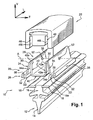
- a wiper blade 10 of the "flat-blade" type which comprises a squeegee 12 extending longitudinally, which is constituted in its lower part by a blade 14 intended to rub against the window to be wiped, and in its upper part, a fixing heel 16.
- the wiper blade 10 also comprises stiffening vertebrae 18 each of which is received in complementary groove formed in a lateral edge of the heel 16.
- the vertebrae 18 are designed to provide rigidity to the wiper blade 10, thus distributing the support force of the squeegee 12 against the window to wipe over its entire length.
- a mounting bracket 20 is mounted on the blade 10, and it is arranged longitudinally globally in the middle of the blade 10, overlapping the heel 16 and the vertebrae 18 of the blade 10.
- the mounting bracket 20 is further adapted to receive a connector 22 for mounting and articulation, about a transverse axis A, of a drive arm 24 of the blade 10 in an alternating scanning movement on the window glass. wipe.
- the mounting bracket 20 consists of a sheet metal plate which has been cut and folded so that the mounting bracket 20 consists of a main longitudinal orientation element having in its lower part lateral claws 26 which are arranged transversely on the other hand. other of the broom 10.
- the mounting bracket 20 has two lateral claws 26 facing each other, each of which extends longitudinally generally over the entire length of the mounting bracket 20.
- the mounting bracket 20 may comprise a greater number of lateral claws 26 which are arranged on each side of the support 20, the length of each claw 26 is then less than the length of the support 20.
- Each claw 26 is adapted to cooperate with a vertebra 18 of the brush for fixing the support 20 on the blade 10.
- each claw 26 defines a longitudinal housing open transversely towards the other claw 26, and in which a portion external transverse 18th of an associated vertebra 18 is received.
- the mounting bracket 20 also has an upper portion 28 which extends above the upper bead 16 of the blade 10 and on which the connector 22 is mounted articulated about the transverse axis A articulation.
- the upper part 28 of the mounting bracket 20 comprises at least one portion 30 which is elastically deformable, to allow, during the attachment of the mounting bracket 20 on the wiper blade 10, a displacement transversely lateral claws relative to each other, from a spaced position shown in FIGS. figures 1 and 2 towards a tightened fastening position, shown in FIG. figure 3 .
- the transverse distance "d1" between the longitudinal inner free transverse end edges 32i of the lower branches 32 of the lower claws 26 is generally equal to the transverse distance "t1" ( figure 3 ) between the longitudinal edges of the outer portions 18e of the two vertebrae 18.
- the space between the free edges 32i of the lower branches 32 thus makes it possible to position the mounting support 20 on the blade 10 so that the outer portion 18e of each vertebra 18 is situated transversely opposite the delimited longitudinal housing. by the claw 26 associated.
- the distance "d2" between the longitudinal edges 32i of the free end of the branches lower 32 of two lateral claws 26 vis-à-vis is less than the distance "d1" described above.
- each vertebra 18 is received without transverse play in the housing delimited by the side claw 26 associated.
- the upper portion 28 of the mounting bracket 20 comprises two vertical longitudinal wings 34, whose lower end longitudinal edge 34i of each lateral wing 34 is connected to the branch.
- upper 36 of each claw 26 which is arranged transversely on the same side of the blade 10.
- the upper portion 28 of the mounting bracket 20 has an intermediate portion 38 of principal orientation of longitudinal main orientation and whose section along a transverse vertical plane is shaped "U". This intermediate portion 38 is arranged transversely between the two lateral wings 34.
- the intermediate portion 38 has a horizontal bottom bottom 40 which is able to rest on an upper face of the heel 16 of the squeegee 12, and two intermediate wings 42 each of which extends vertically upwards from a longitudinal end edge transverse 40a of the bottom 40.
- each lateral flange 42 is connected to the upper end longitudinal edge of the associated intermediate flange 42 via an elastically deformable portion 30.
- each lateral wing 34 is connected to the intermediate portion 38 via an elastically deformable portion 30.
- each lateral wing 34 is situated transversely at a distance from the associated intermediate wing 42, that is to say that their vertical longitudinal faces 34a, 42a facing each other are distant from one another.
- each lateral flange 34 and the associated intermediate flange 42 are placed transversely against one another at their vertical longitudinal faces facing each other 34a, 42a , forming a wall 44 of longitudinal main vertical orientation which extends upwardly from the bottom 40 of the intermediate portion 38.
- each wall 44 of the support 20 thus formed by a lateral flange 32 and the associated intermediate flange 42 is adapted to be received in a vertical longitudinal housing 46 of the connector 22 which is opening vertically. downward at a lower face of the connector 22.
- Each housing 46 of the connector 22 is of dimensions that are substantially complementary to those of the associated wall 44, so that each vertical wall 44 is received without transverse clearance in the associated housing 44, when the connector 22 is in the mounted position on the mounting bracket 22 .
- each lateral flange 34 of the mounting bracket can not deviate transversely from the associated intermediate flange 42.
- the lateral claws 26 of the mounting bracket 20 can not move transversely from their close mounting positions shown in FIG. figure 3 , to their position apart represented to the figure 2 .
- An accidental disconnection of the mounting bracket 20 from the brush 10 can not take place.
- the connector 22 therefore performs a locking function of the mounting bracket 20 in position on the blade 10.
- the mounting support 20 is naturally in the form shown in FIG. figure 2 , that is to say that the lateral claws 26 are in the transversely spaced position, the elastically deformable portions 30 thus provide an elastic return of the claws 26 in the separated position.
- the elastically deformable portions 30 always exert this same return force tending to spread transversely the lateral claws 26.
- FIGS. 4 and 5 an alternative embodiment of the mounting bracket 20 according to the invention according to which the upper portion 28 of the mounting bracket 20 comprises means for locking the lateral wings 34 in a position contiguous against the intermediate wings 42 of the intermediate portion 38.
- the locking means comprise a finger 48 of transverse main orientation which is integral with each lateral wing 34, and which is adapted to be received in a complementary housing 50 made in the intermediate wing 42 associated with the lateral wing 34 .
- each finger 48 and the associated housing 50 is determined so as to prevent any sliding of the finger 48 in the associated housing 50 in the transverse direction.
- each finger 48 is made so that they extend at the level of the longitudinal face external vertical 34e of the associated lateral wing, and each finger 48 is able to be plastically deformed for its introduction into the associated housing 50.
- the upper part 28 of the support 20 comprises two walls 44 - distributed generally symmetrically with respect to a median vertical longitudinal plane of the mounting support 20.
- the upper part 28 of the mounting bracket 20 has only one wall 44 which is then formed by the two only lateral wings 34.
- the two lateral wings 34 are placed side by side against each other, at the level of the longitudinal vertical face vis-a-vis 34a, when the lateral claws 26 are in close position of mounting, and when the claws lateral 26 are in spaced position, the vertical longitudinal faces vis-à-vis the two side wings 34 are spaced apart from each other.
- the connector 22 then comprises a single housing 46 which is associated with this single wall 44 of the upper part 28.
- a first side wing 34 carries the finger 48 and the other side wing 34 carries the associated housing 50.
- the connector is able to be hingedly mounted on the support 20 around the transverse axis A.
- the mounting support 20 comprises a circular orifice 52 of articulation coaxial with the transverse axis A, which is formed in each lateral wing 34 and in each intermediate wing 42.
- the connector 22 has an internal tongue 54 which projects transversely with respect to each vertical vertical longitudinal face 46i of each housing 46, and which is adapted to be received in an associated orifice 52 of a lateral wing 34 or a wing intermediary 42.
- Each tongue 54 has a generally circular shape complementary to that of the associated orifice 52 and coaxial with the transverse axis A, so that the tongues 54 make it possible to articulate the connector 22 with respect to the support 20 around the A axis, and so that it can achieve the locking longitudinally and transversely of the connector 22 in the mounted position on the support 20.
Landscapes
- Engineering & Computer Science (AREA)
- Mechanical Engineering (AREA)
- Surgical Instruments (AREA)
- Pivots And Pivotal Connections (AREA)
- Prostheses (AREA)
- Insertion Pins And Rivets (AREA)
- Mutual Connection Of Rods And Tubes (AREA)
- Hinges (AREA)
- Coating With Molten Metal (AREA)
- Chemically Coating (AREA)
- Cleaning And De-Greasing Of Metallic Materials By Chemical Methods (AREA)
Claims (8)
- Träger (20) zur Montage eines Wischerblattes (10) mit länglicher Hauptausrichtung auf einem Antriebsarm des Wischerblattes (10), der geeignet ist, auf dem Wischerblatt (10) befestigt zu werden und auf dem der Antriebsarm geeignet ist, artikuliert über ein Montage- und Artikulationsverbindungsstück (22) montiert zu werden,
wobei der Montageträger (20) aus einem einzigen Stück durch Ausschneiden und Knicken einer Metallplatte realisiert wird und wenigsten zwei untere, laterale Klauen (26) gegenüber umfasst, die transversal auf jeder Seite des Trägers (20) angeordnet sind und von denen jede geeignet ist, mit einem Teil (18e) zusammenzuwirken, der für die Befestigung des Trägers (20) auf dem Wischerblatt (10) einem Glied (18) des Wischerblattes (10) zugeordnet ist, und einen oberen Teil (28), auf dem das Verbindungsstück (22) geeignet ist, artikuliert um eine transversale Artikulationsachse A montiert zu werden,
wobei der obere Teil (28) wenigstens einen elastisch verformbaren Abschnitt (30) umfasst, der geeignet ist, sich bei der Montage und der Befestigung des Trägers (20) zur Montage auf dem Wischerblatt (10) zu verformen, um eine global transversale Bewegung der lateralen Klauen (26) jeweils zueinander wenigstens zwischen einer beabstandeten Position, in der wenigstens eine Klaue (26) nicht mit dem Teil (18e) des zugeordneten Gliedes (18) zusammenwirkt, um die Montage des Trägers (20) auf dem Wischerblatt (10) zu erlauben, und einer angenäherten Befestigungsposition des Trägers (20), in der jede laterale Klaue (26) mit der Klaue (18e) des zugeordneten Gliedes (18) zusammenwirkt, zu erlauben,
wobei der obere Teil (28) zwei laterale, längliche, vertikale Flügel (34) umfasst, deren unteres Ende (34) jedes Flügels (34) mit einer lateralen Klaue (26) verbunden ist, und die oberen Enden der zwei Flügel (34) mit dem genannten wenigstens einen elastisch verformbaren Abschnitt (30) verbunden sind,
dadurch gekennzeichnet, dass der obere Teil (28) einen intermediären Abschnitt (38) umfasst, der transversal zwischen den zwei lateralen Flügeln (34) angeordnet ist, wobei jeder laterale Flügel (34) an den intermediären Abschnitt (38) durch einen zugeordneten, elastisch verformbren Abschnitt (30) angeschlossen ist,
dass der intermediäre Abschnitt (38) einen horizontalen Boden (40) mit länglicher Hauptausrichtung umfasst, der geeignet ist, sich auf eine obere Seite des Wischerblattes (10) aufzustützen, und zwei intermediäre Flügel (42), von denen sich jeder von einem länglichen Rand (40a) mit transversalem Ende des Bodens (40) vertikal nach oben erstreckt,
und dass der obere längliche Boden jedes intermediären Flügels (42) mit dem oberen länglichen Rand eines lateralen Flügels (34) verbunden ist, der durch den zugeordneten elastisch verformbaren Abschnitt zugeordnet ist. - Träger (20) gemäß dem vorherigen Anspruch, dadurch gekennzeichnet, dass jeder laterale Flügel (34) und der zugeordnete intermediäre Flügel transversal jeweils gegeneinander an ihren vertikalen, länglichen Seiten (34a, 42a) gegenüber zugeordnet sind und dabei eine kleine vertikale Wand (44) bilden, wenn die lateralen Klauen (26) sich in angenäherter Befestigungsposition befinden, und dass, wenn die lateralen Klauen (26) sich in einer beabstandeten Position befinden, der genannte laterale Flügel (34) und der genannte zugeordnete intermediäre Flügel (42) transversal voneinander beabstandet sind.
- Träger (20) gemäß Anspruch 1 oder 2, dadurch gekennzeichnet, dass die zwei lateralen Flügel (34) an ihren länglichen vertikalen Seiten (34a) gegenüber transversal aneinander angefügt sind und eine vertikale Wand (44) bilden, wenn die lateralen Klauen (26) sich in angenäherter Befestigungsposition befinden, und dass, wenn die lateralen Klauen (26) sich in einer beabstandeten Position befinden, die lateralen Flügel (34) transversal voneinander beabstandet sind.
- Träger (20) gemäß Anspruch 2 oder 3, dadurch gekennzeichnet, dass jede kleine Wand (44) Feststellmittel (48, 50) der Flügel (34, 42) in einander angefügter Position umfasst.
- Träger (20) gemäß dem vorherigen Anspruch, dadurch gekennzeichnet, dass die Feststellmittel einen Finger (48) umfassen, der mit einem Flügel (34, 42) fest verbunden ist und der in einer komplementären Aufnahme (50) des zugeordneten Flügels (34, 42) aufgenommen wird.
- Träger (20) gemäß Anspruch 2 bis 5, dadurch gekennzeichnet, dass jede kleine Wand (44) geeignet ist, ohne transversales Spiel in einer komplementären Aufnahme (46) des Verbindungsstücks (22) mit vertikaler, länglicher Hauptausrichtung aufgenommen zu werden, wenn das Verbindungsstück (22) auf dem Artikulationsträger (20) montiert ist.
- Träger (20) gemäß dem vorherigen Anspruch, dadurch gekennzeichnet, dass jeder Flügel (34, 42) des Trägers (20) eine zur transversalen Artikulationsachse A koaxiale Öffnung (52) umfasst, die geeignet ist, eine zugeordnete, interne, transversale Zunge (54) aufzunehmen, die im Verhältnis zu einer internen, vertikalen, länglichen Seite (46i) der zugeordneten Aufnahme (46) hervorsteht, um die Montage und die Artikulation um die transversale Achse A des Verbindungsstücks (22) auf dem Träger (20) zu realisieren.
- Wischerblatt (10), dadurch gekennzeichnet, dass es einen Träger (20) zur Montage gemäß einem der vorherigen Ansprüche umfasst.
Applications Claiming Priority (2)
| Application Number | Priority Date | Filing Date | Title |
|---|---|---|---|
| FR0512147A FR2893896B1 (fr) | 2005-11-30 | 2005-11-30 | Support de montage d'un balai d'essuie-glace sur un bras d'entrainement realise en tole pliee |
| PCT/EP2006/068959 WO2007063051A1 (fr) | 2005-11-30 | 2006-11-27 | Support de montage d'un balai d'essuie-glace sur un bras d'entrainement realise en tôle pliee |
Publications (2)
| Publication Number | Publication Date |
|---|---|
| EP1996435A1 EP1996435A1 (de) | 2008-12-03 |
| EP1996435B1 true EP1996435B1 (de) | 2011-10-19 |
Family
ID=36917329
Family Applications (1)
| Application Number | Title | Priority Date | Filing Date |
|---|---|---|---|
| EP06819786A Not-in-force EP1996435B1 (de) | 2005-11-30 | 2006-11-27 | Träger zur montage eines scheibenwischerblatts an einem antriebsarm aus gebogenem blech |
Country Status (11)
| Country | Link |
|---|---|
| US (1) | US8230546B2 (de) |
| EP (1) | EP1996435B1 (de) |
| JP (1) | JP2009517279A (de) |
| KR (1) | KR20080077167A (de) |
| CN (1) | CN101312862A (de) |
| AT (1) | ATE529309T1 (de) |
| BR (1) | BRPI0619348A2 (de) |
| CA (1) | CA2631363A1 (de) |
| FR (1) | FR2893896B1 (de) |
| RU (1) | RU2008126296A (de) |
| WO (1) | WO2007063051A1 (de) |
Families Citing this family (14)
| Publication number | Priority date | Publication date | Assignee | Title |
|---|---|---|---|---|
| WO2010016000A1 (en) * | 2008-08-05 | 2010-02-11 | Teklas Kaucuk Sanayi Ve Ticaret A.S. | A windscreen wiper |
| US20100139026A1 (en) * | 2008-12-04 | 2010-06-10 | Chin Pech Co., Ltd. | Wiper Blade Spoiler Assembly |
| DE102009000864A1 (de) * | 2009-02-13 | 2010-08-19 | Robert Bosch Gmbh | Wischblatt für einen Scheibenwischer |
| EP2236366B1 (de) * | 2009-04-02 | 2011-06-29 | Federal-Mogul S.A. | Scheibenwischvorrichtung |
| WO2010142339A1 (en) * | 2009-06-11 | 2010-12-16 | Federal-Mogul S.A. | Windscreen wiper device |
| DE102011004637A1 (de) | 2011-02-24 | 2012-08-30 | Robert Bosch Gmbh | Wischblatt zum Reinigen von Scheiben insbesondere von Kraftfahrzeugen |
| DE102011078199A1 (de) * | 2011-06-28 | 2013-01-03 | Robert Bosch Gmbh | Wischvorrichtung |
| DE102011079535A1 (de) * | 2011-07-21 | 2013-01-24 | Robert Bosch Gmbh | Wischvorrichtung |
| DE102011054021A1 (de) * | 2011-09-28 | 2013-03-28 | Valeo Systèmes d'Essuyage | Wischblatt zum Reinigen von Fahrzeugscheiben |
| US9616854B2 (en) * | 2013-04-25 | 2017-04-11 | Trico Products Corporation | Mounting assembly for wiper blade and wiper arm |
| FR3016589B1 (fr) * | 2014-01-17 | 2016-01-22 | Valeo Systemes Dessuyage | Organe longitudinal de retenue d'une vertebre de rigidification et/ou de maintien d'une lame d'essuyage pour un balai d'essuie-glace |
| DE102015218676A1 (de) * | 2015-09-29 | 2017-03-30 | Robert Bosch Gmbh | Wischblattvorrichtung und Verfahren zur Montage und/oder Demontage einer Wischblattvorrichtung |
| CN107985266A (zh) * | 2017-11-14 | 2018-05-04 | 广州沿江科技有限公司 | 一种应用于汽车上的无骨雨刷器 |
| CN107914672A (zh) * | 2017-11-14 | 2018-04-17 | 广州沿江科技有限公司 | 一种无骨雨刷 |
Family Cites Families (8)
| Publication number | Priority date | Publication date | Assignee | Title |
|---|---|---|---|---|
| US3390415A (en) * | 1945-12-22 | 1968-07-02 | Trico Products Corp | Wiping blade for curved windshields |
| GB678149A (en) * | 1946-01-29 | 1952-08-27 | Productive Inventions Inc | Improvements in or relating to connection means for windscreen wipers |
| US2634446A (en) * | 1946-05-11 | 1953-04-14 | Gen Motors Corp | Windshield wiper blade construction and mounting |
| DE19641042A1 (de) * | 1996-10-04 | 1998-04-09 | Bosch Gmbh Robert | Wischblatt für Scheiben von Kraftfahrzeugen |
| DE19860644A1 (de) * | 1998-12-29 | 2000-07-06 | Bosch Gmbh Robert | Vorrichtung zum gelenkigen Verbinden eines Wischblatts für Scheiben von Kraftfahrzeugen mit einem Wischerarm und Verfahren zum Herstellen dieser Verbindung |
| DE50104852D1 (de) * | 2000-10-28 | 2005-01-20 | Bosch Gmbh Robert | Vorrichtung zum lösbaren, gelenkigen verbinden eines wischblatts zum reinigen von scheiben mit einem wischerarm |
| DE10065124A1 (de) * | 2000-12-28 | 2002-07-04 | Bosch Gmbh Robert | Vorrichtung zum lösbaren Verbinden eines Wischblatts mit einem Wischerarm |
| FR2847221B1 (fr) * | 2002-11-19 | 2006-08-04 | Valeo Systemes Dessuyage | Essuie-glace de vehicule comportant un bras et un connecteur d'articulation realises d'une piece par moulage en matiere plastique |
-
2005
- 2005-11-30 FR FR0512147A patent/FR2893896B1/fr not_active Expired - Fee Related
-
2006
- 2006-11-27 AT AT06819786T patent/ATE529309T1/de not_active IP Right Cessation
- 2006-11-27 US US12/095,657 patent/US8230546B2/en not_active Expired - Fee Related
- 2006-11-27 KR KR1020087014023A patent/KR20080077167A/ko not_active Ceased
- 2006-11-27 WO PCT/EP2006/068959 patent/WO2007063051A1/fr not_active Ceased
- 2006-11-27 EP EP06819786A patent/EP1996435B1/de not_active Not-in-force
- 2006-11-27 JP JP2008542746A patent/JP2009517279A/ja active Pending
- 2006-11-27 BR BRPI0619348-0A patent/BRPI0619348A2/pt not_active Application Discontinuation
- 2006-11-27 RU RU2008126296/11A patent/RU2008126296A/ru unknown
- 2006-11-27 CN CNA2006800433533A patent/CN101312862A/zh active Pending
- 2006-11-27 CA CA002631363A patent/CA2631363A1/fr not_active Abandoned
Also Published As
| Publication number | Publication date |
|---|---|
| FR2893896A1 (fr) | 2007-06-01 |
| CA2631363A1 (fr) | 2007-06-07 |
| JP2009517279A (ja) | 2009-04-30 |
| US8230546B2 (en) | 2012-07-31 |
| WO2007063051A1 (fr) | 2007-06-07 |
| FR2893896B1 (fr) | 2008-02-01 |
| EP1996435A1 (de) | 2008-12-03 |
| CN101312862A (zh) | 2008-11-26 |
| BRPI0619348A2 (pt) | 2011-09-27 |
| RU2008126296A (ru) | 2010-01-10 |
| US20100218328A1 (en) | 2010-09-02 |
| ATE529309T1 (de) | 2011-11-15 |
| KR20080077167A (ko) | 2008-08-21 |
Similar Documents
| Publication | Publication Date | Title |
|---|---|---|
| EP1937524B1 (de) | Verbinder zum montieren und verbinden eines wischblattes mit einem antriebsarmende | |
| EP1641663B1 (de) | Kraftfahrzeugscheibenwischer mit einem arm und einem gelenkteil | |
| EP1436179B1 (de) | Scheibenwischer für kraftfahrzeug mit sicherheitshaken | |
| EP2209676B1 (de) | Endstück für ein wischerblatt | |
| EP0410854B1 (de) | Beweglicher Luftableiter für Scheibenwischerblatt, insbesondere für Kraftfahrzeug | |
| EP2152551B1 (de) | Verbindungsvorrichtung mit mittel zur kippbegrenzung | |
| EP1919746B1 (de) | Einen zweiteiligen stützhalter umfassendes windschutzscheibenwischerblatt | |
| EP1874598B1 (de) | Anordnung zur befestigung eines wischerblatts an einem ende eines antriebsarms | |
| EP1996435A1 (de) | Träger zur montage eines scheibenwischerblatts an einem antriebsarm aus gebogenem blech | |
| EP3118070B1 (de) | Organ für ein verbindungssystem eines wischerblatts | |
| EP1874597B1 (de) | Halter zur befestigung eines wischerblatts am ende eines antriebsarms, der aus zwei teilen besteht | |
| FR2743042A1 (fr) | Balai d'essuie-glace courbe pour vehicule automobile comportant une raclette decalee transversalement | |
| EP2170662A1 (de) | Scheibenwischerblatthalter, dessen blatt einen steg enthält, der sich in dem strukturelement bewegen kann | |
| FR3063952A1 (fr) | Balai d'essuie-glace comprenant une monture centrale articulee | |
| FR3010366A1 (fr) | Dispositif de fixation d'un dispositif d'essuie-glace | |
| WO2016150739A1 (fr) | Chape pour bras d'entraînement d'un balai d'essuie-glace | |
| EP0664247B1 (de) | Kraftfahrzeugscheibenwischer mit aerodynamischem Windabweiser | |
| WO2025061787A1 (fr) | Balai d'essuie-glace | |
| EP0532385B1 (de) | Luftleitvorrichtung für Scheibenwischer und Scheibenwischer mit einer solchen Luftleitvorrichtung | |
| WO2025247818A1 (fr) | Balai d'essuie-glace | |
| WO2025061784A1 (fr) | Balai d'essuie-glace | |
| FR2758510A1 (fr) | Essuie-glace de vehicule automobile comportant un deflecteur aerodynamique et un accessoire rapporte sur le deflecteur | |
| WO2018192762A1 (fr) | Lame d'essuyage et corps longitudinal pour un balai d'essuie-glace, et balai d'essuie-glace comportant une telle lame et un tel corps | |
| FR2921052A1 (fr) | Etui de conditionnement de balai d'essuyage comportant deux parois articulees | |
| FR2770473A1 (fr) | Ensemble d'entretoises pour essuie-glace de vehicule automobile comportant un deflecteur aerodynamique et un accessoire rapporte sur le deflecteur |
Legal Events
| Date | Code | Title | Description |
|---|---|---|---|
| PUAI | Public reference made under article 153(3) epc to a published international application that has entered the european phase |
Free format text: ORIGINAL CODE: 0009012 |
|
| 17P | Request for examination filed |
Effective date: 20080619 |
|
| AK | Designated contracting states |
Kind code of ref document: A1 Designated state(s): AT BE BG CH CY CZ DE DK EE ES FI FR GB GR HU IE IS IT LI LT LU LV MC NL PL PT RO SE SI SK TR |
|
| 17Q | First examination report despatched |
Effective date: 20090901 |
|
| GRAP | Despatch of communication of intention to grant a patent |
Free format text: ORIGINAL CODE: EPIDOSNIGR1 |
|
| DAX | Request for extension of the european patent (deleted) | ||
| GRAS | Grant fee paid |
Free format text: ORIGINAL CODE: EPIDOSNIGR3 |
|
| GRAA | (expected) grant |
Free format text: ORIGINAL CODE: 0009210 |
|
| RIN1 | Information on inventor provided before grant (corrected) |
Inventor name: BAUD, FREDERIC Inventor name: LAURENS, ROMAIN |
|
| AK | Designated contracting states |
Kind code of ref document: B1 Designated state(s): AT BE BG CH CY CZ DE DK EE ES FI FR GB GR HU IE IS IT LI LT LU LV MC NL PL PT RO SE SI SK TR |
|
| REG | Reference to a national code |
Ref country code: GB Ref legal event code: FG4D Free format text: NOT ENGLISH |
|
| REG | Reference to a national code |
Ref country code: CH Ref legal event code: EP |
|
| REG | Reference to a national code |
Ref country code: IE Ref legal event code: FG4D |
|
| REG | Reference to a national code |
Ref country code: DE Ref legal event code: R096 Ref document number: 602006025321 Country of ref document: DE Effective date: 20120112 |
|
| REG | Reference to a national code |
Ref country code: NL Ref legal event code: VDEP Effective date: 20111019 |
|
| LTIE | Lt: invalidation of european patent or patent extension |
Effective date: 20111019 |
|
| REG | Reference to a national code |
Ref country code: AT Ref legal event code: MK05 Ref document number: 529309 Country of ref document: AT Kind code of ref document: T Effective date: 20111019 |
|
| PG25 | Lapsed in a contracting state [announced via postgrant information from national office to epo] |
Ref country code: IS Free format text: LAPSE BECAUSE OF FAILURE TO SUBMIT A TRANSLATION OF THE DESCRIPTION OR TO PAY THE FEE WITHIN THE PRESCRIBED TIME-LIMIT Effective date: 20120219 Ref country code: LT Free format text: LAPSE BECAUSE OF FAILURE TO SUBMIT A TRANSLATION OF THE DESCRIPTION OR TO PAY THE FEE WITHIN THE PRESCRIBED TIME-LIMIT Effective date: 20111019 |
|
| REG | Reference to a national code |
Ref country code: IE Ref legal event code: FD4D |
|
| PG25 | Lapsed in a contracting state [announced via postgrant information from national office to epo] |
Ref country code: GR Free format text: LAPSE BECAUSE OF FAILURE TO SUBMIT A TRANSLATION OF THE DESCRIPTION OR TO PAY THE FEE WITHIN THE PRESCRIBED TIME-LIMIT Effective date: 20120120 Ref country code: LV Free format text: LAPSE BECAUSE OF FAILURE TO SUBMIT A TRANSLATION OF THE DESCRIPTION OR TO PAY THE FEE WITHIN THE PRESCRIBED TIME-LIMIT Effective date: 20111019 Ref country code: NL Free format text: LAPSE BECAUSE OF FAILURE TO SUBMIT A TRANSLATION OF THE DESCRIPTION OR TO PAY THE FEE WITHIN THE PRESCRIBED TIME-LIMIT Effective date: 20111019 Ref country code: PT Free format text: LAPSE BECAUSE OF FAILURE TO SUBMIT A TRANSLATION OF THE DESCRIPTION OR TO PAY THE FEE WITHIN THE PRESCRIBED TIME-LIMIT Effective date: 20120220 Ref country code: SI Free format text: LAPSE BECAUSE OF FAILURE TO SUBMIT A TRANSLATION OF THE DESCRIPTION OR TO PAY THE FEE WITHIN THE PRESCRIBED TIME-LIMIT Effective date: 20111019 Ref country code: SE Free format text: LAPSE BECAUSE OF FAILURE TO SUBMIT A TRANSLATION OF THE DESCRIPTION OR TO PAY THE FEE WITHIN THE PRESCRIBED TIME-LIMIT Effective date: 20111019 |
|
| PG25 | Lapsed in a contracting state [announced via postgrant information from national office to epo] |
Ref country code: MC Free format text: LAPSE BECAUSE OF NON-PAYMENT OF DUE FEES Effective date: 20111130 Ref country code: CY Free format text: LAPSE BECAUSE OF FAILURE TO SUBMIT A TRANSLATION OF THE DESCRIPTION OR TO PAY THE FEE WITHIN THE PRESCRIBED TIME-LIMIT Effective date: 20111019 |
|
| REG | Reference to a national code |
Ref country code: CH Ref legal event code: PL |
|
| PG25 | Lapsed in a contracting state [announced via postgrant information from national office to epo] |
Ref country code: LI Free format text: LAPSE BECAUSE OF NON-PAYMENT OF DUE FEES Effective date: 20111130 Ref country code: CH Free format text: LAPSE BECAUSE OF NON-PAYMENT OF DUE FEES Effective date: 20111130 Ref country code: EE Free format text: LAPSE BECAUSE OF FAILURE TO SUBMIT A TRANSLATION OF THE DESCRIPTION OR TO PAY THE FEE WITHIN THE PRESCRIBED TIME-LIMIT Effective date: 20111019 Ref country code: SK Free format text: LAPSE BECAUSE OF FAILURE TO SUBMIT A TRANSLATION OF THE DESCRIPTION OR TO PAY THE FEE WITHIN THE PRESCRIBED TIME-LIMIT Effective date: 20111019 Ref country code: CZ Free format text: LAPSE BECAUSE OF FAILURE TO SUBMIT A TRANSLATION OF THE DESCRIPTION OR TO PAY THE FEE WITHIN THE PRESCRIBED TIME-LIMIT Effective date: 20111019 Ref country code: DK Free format text: LAPSE BECAUSE OF FAILURE TO SUBMIT A TRANSLATION OF THE DESCRIPTION OR TO PAY THE FEE WITHIN THE PRESCRIBED TIME-LIMIT Effective date: 20111019 Ref country code: IE Free format text: LAPSE BECAUSE OF FAILURE TO SUBMIT A TRANSLATION OF THE DESCRIPTION OR TO PAY THE FEE WITHIN THE PRESCRIBED TIME-LIMIT Effective date: 20111019 Ref country code: BG Free format text: LAPSE BECAUSE OF FAILURE TO SUBMIT A TRANSLATION OF THE DESCRIPTION OR TO PAY THE FEE WITHIN THE PRESCRIBED TIME-LIMIT Effective date: 20120119 |
|
| PLBE | No opposition filed within time limit |
Free format text: ORIGINAL CODE: 0009261 |
|
| STAA | Information on the status of an ep patent application or granted ep patent |
Free format text: STATUS: NO OPPOSITION FILED WITHIN TIME LIMIT |
|
| PG25 | Lapsed in a contracting state [announced via postgrant information from national office to epo] |
Ref country code: RO Free format text: LAPSE BECAUSE OF FAILURE TO SUBMIT A TRANSLATION OF THE DESCRIPTION OR TO PAY THE FEE WITHIN THE PRESCRIBED TIME-LIMIT Effective date: 20111019 Ref country code: PL Free format text: LAPSE BECAUSE OF FAILURE TO SUBMIT A TRANSLATION OF THE DESCRIPTION OR TO PAY THE FEE WITHIN THE PRESCRIBED TIME-LIMIT Effective date: 20111019 Ref country code: IT Free format text: LAPSE BECAUSE OF FAILURE TO SUBMIT A TRANSLATION OF THE DESCRIPTION OR TO PAY THE FEE WITHIN THE PRESCRIBED TIME-LIMIT Effective date: 20111019 |
|
| 26N | No opposition filed |
Effective date: 20120720 |
|
| GBPC | Gb: european patent ceased through non-payment of renewal fee |
Effective date: 20120119 |
|
| PG25 | Lapsed in a contracting state [announced via postgrant information from national office to epo] |
Ref country code: GB Free format text: LAPSE BECAUSE OF NON-PAYMENT OF DUE FEES Effective date: 20120119 |
|
| REG | Reference to a national code |
Ref country code: DE Ref legal event code: R097 Ref document number: 602006025321 Country of ref document: DE Effective date: 20120720 |
|
| PG25 | Lapsed in a contracting state [announced via postgrant information from national office to epo] |
Ref country code: AT Free format text: LAPSE BECAUSE OF FAILURE TO SUBMIT A TRANSLATION OF THE DESCRIPTION OR TO PAY THE FEE WITHIN THE PRESCRIBED TIME-LIMIT Effective date: 20111019 |
|
| PG25 | Lapsed in a contracting state [announced via postgrant information from national office to epo] |
Ref country code: ES Free format text: LAPSE BECAUSE OF FAILURE TO SUBMIT A TRANSLATION OF THE DESCRIPTION OR TO PAY THE FEE WITHIN THE PRESCRIBED TIME-LIMIT Effective date: 20120130 |
|
| PG25 | Lapsed in a contracting state [announced via postgrant information from national office to epo] |
Ref country code: LU Free format text: LAPSE BECAUSE OF NON-PAYMENT OF DUE FEES Effective date: 20111127 |
|
| PG25 | Lapsed in a contracting state [announced via postgrant information from national office to epo] |
Ref country code: FI Free format text: LAPSE BECAUSE OF FAILURE TO SUBMIT A TRANSLATION OF THE DESCRIPTION OR TO PAY THE FEE WITHIN THE PRESCRIBED TIME-LIMIT Effective date: 20111019 |
|
| PG25 | Lapsed in a contracting state [announced via postgrant information from national office to epo] |
Ref country code: TR Free format text: LAPSE BECAUSE OF FAILURE TO SUBMIT A TRANSLATION OF THE DESCRIPTION OR TO PAY THE FEE WITHIN THE PRESCRIBED TIME-LIMIT Effective date: 20111019 |
|
| PG25 | Lapsed in a contracting state [announced via postgrant information from national office to epo] |
Ref country code: HU Free format text: LAPSE BECAUSE OF FAILURE TO SUBMIT A TRANSLATION OF THE DESCRIPTION OR TO PAY THE FEE WITHIN THE PRESCRIBED TIME-LIMIT Effective date: 20111019 |
|
| REG | Reference to a national code |
Ref country code: FR Ref legal event code: PLFP Year of fee payment: 10 |
|
| REG | Reference to a national code |
Ref country code: FR Ref legal event code: PLFP Year of fee payment: 11 |
|
| REG | Reference to a national code |
Ref country code: FR Ref legal event code: PLFP Year of fee payment: 12 |
|
| PGFP | Annual fee paid to national office [announced via postgrant information from national office to epo] |
Ref country code: DE Payment date: 20191115 Year of fee payment: 14 |
|
| PGFP | Annual fee paid to national office [announced via postgrant information from national office to epo] |
Ref country code: FR Payment date: 20191129 Year of fee payment: 14 Ref country code: BE Payment date: 20191126 Year of fee payment: 14 |
|
| REG | Reference to a national code |
Ref country code: DE Ref legal event code: R119 Ref document number: 602006025321 Country of ref document: DE |
|
| REG | Reference to a national code |
Ref country code: BE Ref legal event code: MM Effective date: 20201130 |
|
| PG25 | Lapsed in a contracting state [announced via postgrant information from national office to epo] |
Ref country code: FR Free format text: LAPSE BECAUSE OF NON-PAYMENT OF DUE FEES Effective date: 20201130 |
|
| PG25 | Lapsed in a contracting state [announced via postgrant information from national office to epo] |
Ref country code: DE Free format text: LAPSE BECAUSE OF NON-PAYMENT OF DUE FEES Effective date: 20210601 |
|
| PG25 | Lapsed in a contracting state [announced via postgrant information from national office to epo] |
Ref country code: BE Free format text: LAPSE BECAUSE OF NON-PAYMENT OF DUE FEES Effective date: 20201130 |