EP1996439B1 - Accouplement articule pour vehicules ferroviaires - Google Patents
Accouplement articule pour vehicules ferroviaires Download PDFInfo
- Publication number
- EP1996439B1 EP1996439B1 EP07712363A EP07712363A EP1996439B1 EP 1996439 B1 EP1996439 B1 EP 1996439B1 EP 07712363 A EP07712363 A EP 07712363A EP 07712363 A EP07712363 A EP 07712363A EP 1996439 B1 EP1996439 B1 EP 1996439B1
- Authority
- EP
- European Patent Office
- Prior art keywords
- coupling
- outer ring
- groove
- ring
- articulated joint
- Prior art date
- Legal status (The legal status is an assumption and is not a legal conclusion. Google has not performed a legal analysis and makes no representation as to the accuracy of the status listed.)
- Ceased
Links
- 230000008878 coupling Effects 0.000 title claims description 86
- 238000010168 coupling process Methods 0.000 title claims description 86
- 238000005859 coupling reaction Methods 0.000 title claims description 86
- 230000036316 preload Effects 0.000 claims 1
- 229910000831 Steel Inorganic materials 0.000 description 2
- 238000004026 adhesive bonding Methods 0.000 description 2
- 238000006073 displacement reaction Methods 0.000 description 2
- 238000005553 drilling Methods 0.000 description 2
- 238000009434 installation Methods 0.000 description 2
- 230000000149 penetrating effect Effects 0.000 description 2
- 239000010959 steel Substances 0.000 description 2
- 230000000694 effects Effects 0.000 description 1
- 230000008030 elimination Effects 0.000 description 1
- 238000003379 elimination reaction Methods 0.000 description 1
- 230000002349 favourable effect Effects 0.000 description 1
- 239000000835 fiber Substances 0.000 description 1
- 238000003780 insertion Methods 0.000 description 1
- 230000037431 insertion Effects 0.000 description 1
- 238000012423 maintenance Methods 0.000 description 1
- 239000000463 material Substances 0.000 description 1
- 239000002184 metal Substances 0.000 description 1
- 230000004048 modification Effects 0.000 description 1
- 238000012986 modification Methods 0.000 description 1
- 230000007935 neutral effect Effects 0.000 description 1
- 230000003716 rejuvenation Effects 0.000 description 1
- 238000000926 separation method Methods 0.000 description 1
- 238000003466 welding Methods 0.000 description 1
Images


Classifications
-
- B—PERFORMING OPERATIONS; TRANSPORTING
- B61—RAILWAYS
- B61G—COUPLINGS; DRAUGHT AND BUFFING APPLIANCES
- B61G5/00—Couplings for special purposes not otherwise provided for
- B61G5/02—Couplings for special purposes not otherwise provided for for coupling articulated trains, locomotives and tenders or the bogies of a vehicle; Coupling by means of a single coupling bar; Couplings preventing or limiting relative lateral movement of vehicles
Definitions
- the invention relates to an articulated coupling for rail vehicles, in which a coupling tab is mounted by means of a spherical bearing in a clutch fork.
- An articulated coupling of the type mentioned is, for example, from the US 5,172,819 A or from the DE 101 53 460 A1 known.
- This is a coupling for semi-permanent connection of wagons. For example, units of ten cars are assembled, which are usually separated only for maintenance purposes.
- the semi-permanent connections between the wagons should help to reduce the impact of impact forces acting on a wagon under the impact conditions of train operation.
- the invention has for its object to provide a suitable for rail vehicles articulated coupling, which is characterized both by a claim-appropriate design and by a particularly efficient manufacturability.
- This joint coupling has an engaging in a coupling fork coupling tab with a spherical bearing, said coupling fork and coupling tab are also referred to as a mother part or father part.
- Parts of the spherical bearing are an inner ring with a convex surface and a cooperating, a sliding bearing outer ring forming with a concave surface which is fixed in an opening of the coupling tab.
- both the outer ring and the coupling tab each have a groove, wherein a clamping ring rests in the groove of the outer ring and at the same time in the groove of the coupling tab.
- the clamping ring is slotted axially as a one-piece metal part; Alternatively, several individual clamping ring segments can be used.
- the attachment of the outer ring in the coupling tab by means of clamping ring on the one hand has the advantage of a simple installation, on the other hand, given no restrictions on the materials due to the elimination of welding.
- a blasted outer ring is usable.
- a small compared to the outer ring and the coupling tab width of the clamping ring allows large-scale investment of the outer ring in the opening of the coupling plate and thus a particularly uniform force application.
- the width of the clamping ring measured in the axial direction is less than 15%, in particular less than 10%, of the width of the outer ring measured in the same direction. The latter width is preferably consistent with the width of the coupling tab.
- the coupling tab has bores which extend from the circumference of the coupling tab to the groove of the coupling tab. These holes serve to receive screws with which the radial Positioning of the clamping ring can be changed at least in sections. In this case, both an increase and a reduction of the radius of the clamping ring come into consideration.
- the clamping ring forming part of the joint coupling is preferably located completely in the groove of the coupling lug.
- the clamping ring is elastically biased so that it rests completely in the groove of the coupling tab, as long as no further forces acting on him. In this positioning of the clamping ring a very simple insertion of the outer ring in the opening of the coupling tab is possible. In order subsequently to connect the clamping ring to the outer ring in a form-fitting manner, only the screws located in the bores have to be tightened, which in this case exert a force on the clamping ring radially inwards.
- the clamping ring When disassembling the universal joint, it may be sufficient in an analogous manner to solve the said screws, so that the clamping ring expands and allows separation of outer ring and coupling tab. If the clamping ring, for example, due to corrosive effects, stuck in the groove of the outer ring, it is advantageously provided the possibility to pull the clamping ring by means of several screws to the outside, in the groove of the coupling tab.
- an end-side screwing of the clamping ring can be provided.
- the advantage of such a screw with screws, which are arranged parallel to the axial direction of the clamping ring and the outer and inner ring can, depending on the geometric conditions in the individual case, in particular lie in a favorable stress distribution, the position of a neutral fiber is utilized.
- a combination of radial and axial arrangement of clamping screws, which act directly or indirectly on the clamping ring, is possible.
- the screws which are provided for pressing the clamping ring in the groove of the outer ring can be secured for example by gluing against loosening.
- a clip made of steel is preferably placed around the openings in the coupling tab as a safeguard against unscrewing of the screws, wherein an attachment on one or symmetrically on both sides can be provided.
- the clamping ring has in an advantageous embodiment in cross-section on a radially inwardly directed, at least one-sided taper.
- the taper is bilaterally, symmetrically to a clamping ring and possibly the radial holes intersecting plane formed.
- the groove in the outer ring has a cross section of the clamping ring adapted, radially inwardly tapering cross section, so that the clamping ring is positionable in the outer ring without play.
- the game of the clamping ring in the groove of the coupling tab preferably remains in completely assembled joint coupling.
- two clamping rings arranged in parallel planes are positioned between the outer ring and the coupling lug.
- the outer surface of the outer ring and the surface of the opening of the coupling tab can be designed to be cylindrical throughout.
- the axial fixing of the outer ring relative to the coupling tab takes place exclusively via the clamping rings.
- a single clamping ring is inserted between the coupling tab and the outer ring.
- the flange of the coupling tab or the outer ring preferably has a bevelled, abutting on the other component edge.
- the end face of the integrally formed on one of the components, in particular the outer ring, flange is preferably aligned with the front surface of the other component, in particular the coupling tab.
- FIG. 1 simplified is shown a joint coupling 1 for rail vehicles whose principal function, for example, from the DE 103 60 289 A1 is known.
- the universal joint 1 for example, for couplings with tie rods, as in the DE 195 43 183 A1 described.
- Another application for the universal joint 1 is in the coupling of supported on a common bogie ends of two articulated vehicle units, as basically in the EP 0 520 301 A1 described, given.
- the universal joint 1 has a spherical bearing 2, by means of which a coupling tab 3 is connected to a coupling fork 4.
- a game of the universal joint 1 in a first direction is denoted by x; Furthermore, a game exists in a direction orthogonal thereto.
- the game x may be the vertical game or the horizontal game.
- the bearing 2 is designed as a sliding bearing, wherein an inner ring 5 is pivotally mounted with a spherical surface 6 in an outer ring 7 with a concave surface 8.
- the inner ring 5 is penetrated by a pin 9, which is held in holes 10 which are located in fork cheeks 11, 12 of the clutch fork 4.
- the holes 10 are to prevent displacement of the bolt 9, covered with flaps 13.
- the outer ring 7 Before assembly of the universal joint 1, the outer ring 7 is blown up by forces acting in the radial direction. This has the advantage that the outer ring 7 along a plane E, which forms a normal to the axis of symmetry A of the spherical bearing 2 arranged symmetry plane of this bearing 2 need not be divided.
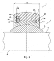
- the constructed as a blasted outer ring outer ring 7 is inserted into a cylindrical opening 14 of the coupling plate 3. Details of the attachment of the outer ring 7 in the opening 14 of the coupling tab 3 are in particular with reference to the Figures 2 and 3 clearly, the embodiments of articulated couplings 1 show, the basic structure of the embodiment according to FIG. 1 equivalent.
- a groove 17 on the outer, substantially cylindrical surface 16 of the outer ring 7 is opposite to a groove 15 in the wall 18 of the opening 14.
- the matching, measured in the axial direction width b of the grooves 15, 17 is about 10% of the width B of the coupling plate 3 and the outer ring 7.
- a clamping ring 18 engages in both grooves 15, 17 and thus provides a connection between the outer ring 7 and the coupling tab 3 ago.
- the clamping ring 18 is due to the elastic bias completely within the groove 15 in the coupling tab.
- the clamping ring 18 is slotted axially, so that the diameter of the clamping ring 18 can be varied by acting on these forces. Is the outer ring 7 during assembly of the universal joint 1 relative to the coupling tab 3 in the final position shown, the diameter of the clamping ring 18 by means of individual screws 19, each penetrating a radially arranged bore 20 in the coupling tab 3, reduced, so that the clamping ring 18 partially engages in the groove 17 of the outer ring 7. The screws 19 are secured by a steel clamp 21 against unscrewing.
- the coupling tab 3 penetrating bore 20 is formed as a threaded bore 22 which has a diameter which falls slightly below the constant width b of the groove 15 of the coupling tab 3.
- the groove 17 of the outer ring 7 has a radially inwardly one-sided ( FIG. 3 ) or on two sides ( Figure 2) conically extending shape, which is adapted to a taper 23 of the clamping ring 18.
- Figure 2 conically extending shape, which is adapted to a taper 23 of the clamping ring 18.
Landscapes
- Engineering & Computer Science (AREA)
- Mechanical Engineering (AREA)
- Clamps And Clips (AREA)
- Snaps, Bayonet Connections, Set Pins, And Snap Rings (AREA)
- Adornments (AREA)
- Pivots And Pivotal Connections (AREA)
Claims (10)
- Accouplement articulé pour véhicules ferroviaires, comprenant une liaison d'accouplement (3) venant en prise dans une fourche d'accouplement (4) et un palier sphérique (2) dans la liaison d'accouplement (3), le palier sphérique (2) présentant une bague interne (5) avec une surface convexe (6), qui est montée de manière à pouvoir pivoter dans une bague externe (7) avec une surface concave (8), la bague externe (7) étant fixée dans une ouverture (14) de la liaison d'accouplement (3), caractérisé en ce que pour la fixation de la bague externe (7) dans l'ouverture (14) de la liaison d'accouplement (3), la bague externe (7) ainsi que la liaison d'accouplement (3) présentent chacune une rainure (15, 17), une bague de serrage (18) s'insérant dans la rainure (17) de la bague externe (7) et en même temps dans la rainure (15) de la liaison d'accouplement (3).
- Accouplement articulé selon la revendication 1, caractérisé en ce que la liaison d'accouplement (3) présente des alésages (20), qui relient la périphérie de la liaison d'accouplement (3) à la rainure (15).
- Accouplement articulé selon la revendication 2, caractérisé par un collier (21) recouvrant les alésages (20).
- Accouplement articulé selon la revendication 2 ou 3, caractérisé par une vis (19) disposée dans l'alésage (20), laquelle est prévue pour solliciter la bague de serrage (18) avec une force dans la direction radiale.
- Accouplement articulé selon la revendication 4, caractérisé en ce que la bague de serrage (18) présente une précontrainte élastique telle qu'elle soit disposée complètement à l'intérieur de la rainure (15) de la liaison d'accouplement (3) sans autre contrainte mécanique.
- Accouplement articulé selon l'une quelconque des revendications 1 à 5, caractérisé en ce que la bague de serrage (18) présente un rétrécissement (23) orienté radialement vers l'intérieur.
- Accouplement articulé selon l'une quelconque des revendications 1 à 6, caractérisé en ce que la bague de serrage (18) est disposée sans jeu dans la rainure (17) de la bague externe (7) et en même temps avec jeu dans la rainure (15) de la liaison d'accouplement (3).
- Accouplement articulé selon l'une quelconque des revendications 1 à 7, caractérisé en ce que la bague externe (7) présente une bride (24) butant contre la liaison d'accouplement (3).
- Accouplement articulé selon la revendication 8, caractérisé en ce que la bride (24) présente un flanc (25) biseauté, s'appliquant contre la liaison d'accouplement (3).
- Accouplement articulé selon l'une quelconque des revendications 1 à 9, caractérisé par deux bagues de serrage (18) venant en prise à chaque fois dans une rainure (17) de la bague externe (7) ainsi que dans une rainure (15) de la liaison d'accouplement (3).
Priority Applications (1)
| Application Number | Priority Date | Filing Date | Title |
|---|---|---|---|
| PL07712363T PL1996439T3 (pl) | 2006-03-11 | 2007-02-28 | Sprzęg przegubowy do pojazdów szynowych |
Applications Claiming Priority (2)
| Application Number | Priority Date | Filing Date | Title |
|---|---|---|---|
| DE102006011425A DE102006011425A1 (de) | 2006-03-11 | 2006-03-11 | Gelenkkupplung für Schienenfahrzeuge |
| PCT/EP2007/051875 WO2007104643A1 (fr) | 2006-03-11 | 2007-02-28 | Accouplement articulé pour véhicules ferroviaires |
Publications (2)
| Publication Number | Publication Date |
|---|---|
| EP1996439A1 EP1996439A1 (fr) | 2008-12-03 |
| EP1996439B1 true EP1996439B1 (fr) | 2010-06-09 |
Family
ID=38066459
Family Applications (1)
| Application Number | Title | Priority Date | Filing Date |
|---|---|---|---|
| EP07712363A Ceased EP1996439B1 (fr) | 2006-03-11 | 2007-02-28 | Accouplement articule pour vehicules ferroviaires |
Country Status (7)
| Country | Link |
|---|---|
| US (1) | US7832575B2 (fr) |
| EP (1) | EP1996439B1 (fr) |
| CN (1) | CN101400560B (fr) |
| DE (2) | DE102006011425A1 (fr) |
| PL (1) | PL1996439T3 (fr) |
| RU (1) | RU2424930C2 (fr) |
| WO (1) | WO2007104643A1 (fr) |
Families Citing this family (7)
| Publication number | Priority date | Publication date | Assignee | Title |
|---|---|---|---|---|
| DE102009057452A1 (de) * | 2009-12-09 | 2011-06-16 | Schaeffler Technologies Gmbh & Co. Kg | Befestigung Gelenklager |
| FR2987332B1 (fr) * | 2012-02-28 | 2014-11-28 | Alstom Transport Sa | Dispositif d'accouplement de deux vehicules, notamment ferroviaires, et ensemble de vehicules correspondant. |
| US9903418B2 (en) | 2014-12-11 | 2018-02-27 | Caterpillar Inc. | Coupling adapter and arrangement for multi-powertrain system |
| WO2018094004A1 (fr) * | 2016-11-17 | 2018-05-24 | Kaci Intermodal Systems, Llc. | Coupleur de rail articulé |
| CN107117185A (zh) * | 2017-06-23 | 2017-09-01 | 中车资阳机车有限公司 | 一种手动型连挂缓冲结构 |
| AT522331B1 (de) * | 2019-07-22 | 2020-10-15 | Siemens Mobility Austria Gmbh | Schienenfahrzeugkupplung |
| CN115056815B (zh) * | 2022-07-14 | 2024-03-12 | 株洲时代新材料科技股份有限公司 | 胶轮列车车端铰接机构 |
Family Cites Families (9)
| Publication number | Priority date | Publication date | Assignee | Title |
|---|---|---|---|---|
| SU1753078A1 (ru) * | 1990-04-10 | 1992-08-07 | Специальное конструкторское бюро транспортного машиностроения | Шарнирное соединение |
| US5172819A (en) * | 1990-05-08 | 1992-12-22 | Westinghouse Air Brake Company | Bearing assembly for an articulated coupling apparatus which connects adjacent ends of a pair of railway cars together |
| US5219082A (en) * | 1990-09-21 | 1993-06-15 | Westinghouse Air Brake Company | Male connection member for an articulated coupling arrangement |
| DE4121080A1 (de) * | 1991-06-26 | 1993-01-14 | Waggon Union Gmbh | Kupplungsvorrichtung fuer die auf einem gemeinsamen drehgestell abgestuetzten enden zweier gelenkig miteinander verbundener fahrzeugeinheiten |
| CH687099A5 (de) * | 1993-03-11 | 1996-09-13 | Johann Gottlieb Aellig | Abdeckelement fuer Schrauben. |
| FI97041C (fi) * | 1994-11-18 | 1996-10-10 | Rautaruukki Oy | Rautatievaunujen pitkä kytkentä |
| CN2296425Y (zh) * | 1996-09-30 | 1998-11-04 | 乐清市联轴器厂 | 十字轴式万向联轴器 |
| DE10153460A1 (de) * | 2001-10-30 | 2003-05-22 | Voith Turbo Scharfenberg Gmbh | Kupplungsvorrichtung für die auf einem gemeinsamen Fahrwerk abgestützten Enden zweier gelenkig miteinander verbundenen, benachbarten Fahrzeugeinheiten eines schienengebundenen Gliederfahrzeuges |
| DE10360289A1 (de) * | 2003-12-20 | 2005-07-21 | Ina-Schaeffler Kg | Kupplungselement für Schienenfahrzeuge |
-
2006
- 2006-03-11 DE DE102006011425A patent/DE102006011425A1/de not_active Withdrawn
-
2007
- 2007-02-28 CN CN2007800088152A patent/CN101400560B/zh not_active Expired - Fee Related
- 2007-02-28 RU RU2008140321/11A patent/RU2424930C2/ru not_active IP Right Cessation
- 2007-02-28 EP EP07712363A patent/EP1996439B1/fr not_active Ceased
- 2007-02-28 WO PCT/EP2007/051875 patent/WO2007104643A1/fr not_active Ceased
- 2007-02-28 DE DE502007004073T patent/DE502007004073D1/de active Active
- 2007-02-28 US US12/224,936 patent/US7832575B2/en not_active Expired - Fee Related
- 2007-02-28 PL PL07712363T patent/PL1996439T3/pl unknown
Also Published As
| Publication number | Publication date |
|---|---|
| EP1996439A1 (fr) | 2008-12-03 |
| WO2007104643A1 (fr) | 2007-09-20 |
| US7832575B2 (en) | 2010-11-16 |
| RU2008140321A (ru) | 2010-04-20 |
| RU2424930C2 (ru) | 2011-07-27 |
| US20090101615A1 (en) | 2009-04-23 |
| DE102006011425A1 (de) | 2007-09-13 |
| CN101400560B (zh) | 2012-03-21 |
| PL1996439T3 (pl) | 2010-11-30 |
| DE502007004073D1 (de) | 2010-07-22 |
| CN101400560A (zh) | 2009-04-01 |
Similar Documents
| Publication | Publication Date | Title |
|---|---|---|
| EP4313719B1 (fr) | Attelage à tampon central automatique pour véhicules ferroviaires, et ensemble d'attelage composé de celui-ci | |
| EP2049381B1 (fr) | Accouplement articulé pour véhicules sur rails | |
| DE102010038067A1 (de) | Formschlussverbindung mit Ausgleich von Lagefehlern | |
| DE2424262A1 (de) | Gewindelose spannvorrichtung | |
| EP3032093B1 (fr) | Dispositif de fixation d'une pale de rotor sur un moyeu de rotor d'une éolienne | |
| EP3096963B1 (fr) | Attache de composant avec surface de support supportant les forces transversales | |
| DE19625318C2 (de) | Konusschraubverbindung für Lamellenpaket-Wellenkupplungen | |
| EP1996439A1 (fr) | Accouplement articule pour vehicules ferroviaires | |
| DE102015108228A1 (de) | Vorrichtung zum Verbinden eines Kupplungsschafts mit einem Wagenkasten eines spurgeführten Fahrzeuges | |
| EP2497964B1 (fr) | Agencement de fixation | |
| DE102011052266A1 (de) | Selbstsichernde Befestigungsmittel sowie Befestigungsanordnung | |
| EP1048544B1 (fr) | Articulation pour rames de véhicules ferroviaires | |
| DE102013011106B4 (de) | Abgasturbolader | |
| EP3770038B1 (fr) | Accouplement de véhicule ferroviaire | |
| EP2062689A1 (fr) | Dispositif de liaison de conduits | |
| EP2471686A1 (fr) | Tendeur à cliquet | |
| DE60101103T2 (de) | Den Kupplungsstoss aufnehmende Kupplung | |
| DE10162910B4 (de) | Klemmspaltmutter | |
| EP2333361A1 (fr) | Fixation d'une rotule | |
| EP2896864A1 (fr) | Système de connexion | |
| EP0014483B1 (fr) | Disque de frein, notamment pour véhicules ferroviaires | |
| DE10309792B4 (de) | Maschinenelement | |
| EP1523392B1 (fr) | Dispositif de serrage pour outils | |
| EP1916432B1 (fr) | Liaison d'arbre et profil d'arrêt destiné à celle-ci | |
| EP1069020B1 (fr) | Dispositif de traction pour véhicules ferroviaires |
Legal Events
| Date | Code | Title | Description |
|---|---|---|---|
| PUAI | Public reference made under article 153(3) epc to a published international application that has entered the european phase |
Free format text: ORIGINAL CODE: 0009012 |
|
| 17P | Request for examination filed |
Effective date: 20081013 |
|
| AK | Designated contracting states |
Kind code of ref document: A1 Designated state(s): DE FR IT PL |
|
| DAX | Request for extension of the european patent (deleted) | ||
| RBV | Designated contracting states (corrected) |
Designated state(s): DE FR IT PL |
|
| GRAP | Despatch of communication of intention to grant a patent |
Free format text: ORIGINAL CODE: EPIDOSNIGR1 |
|
| GRAS | Grant fee paid |
Free format text: ORIGINAL CODE: EPIDOSNIGR3 |
|
| GRAA | (expected) grant |
Free format text: ORIGINAL CODE: 0009210 |
|
| AK | Designated contracting states |
Kind code of ref document: B1 Designated state(s): DE FR IT PL |
|
| REF | Corresponds to: |
Ref document number: 502007004073 Country of ref document: DE Date of ref document: 20100722 Kind code of ref document: P |
|
| REG | Reference to a national code |
Ref country code: PL Ref legal event code: T3 |
|
| PLBE | No opposition filed within time limit |
Free format text: ORIGINAL CODE: 0009261 |
|
| STAA | Information on the status of an ep patent application or granted ep patent |
Free format text: STATUS: NO OPPOSITION FILED WITHIN TIME LIMIT |
|
| REG | Reference to a national code |
Ref country code: DE Ref legal event code: R097 Ref document number: 502007004073 Country of ref document: DE Effective date: 20110309 |
|
| REG | Reference to a national code |
Ref country code: DE Ref legal event code: R081 Ref document number: 502007004073 Country of ref document: DE Owner name: SCHAEFFLER TECHNOLOGIES AG & CO. KG, DE Free format text: FORMER OWNER: SCHAEFFLER KG, 91074 HERZOGENAURACH, DE Effective date: 20120828 Ref country code: DE Ref legal event code: R081 Ref document number: 502007004073 Country of ref document: DE Owner name: SCHAEFFLER TECHNOLOGIES GMBH & CO. KG, DE Free format text: FORMER OWNER: SCHAEFFLER KG, 91074 HERZOGENAURACH, DE Effective date: 20120828 |
|
| REG | Reference to a national code |
Ref country code: DE Ref legal event code: R081 Ref document number: 502007004073 Country of ref document: DE Owner name: SCHAEFFLER TECHNOLOGIES AG & CO. KG, DE Free format text: FORMER OWNER: SCHAEFFLER TECHNOLOGIES AG & CO. KG, 91074 HERZOGENAURACH, DE Effective date: 20140218 Ref country code: DE Ref legal event code: R081 Ref document number: 502007004073 Country of ref document: DE Owner name: SCHAEFFLER TECHNOLOGIES GMBH & CO. KG, DE Free format text: FORMER OWNER: SCHAEFFLER TECHNOLOGIES AG & CO. KG, 91074 HERZOGENAURACH, DE Effective date: 20140218 |
|
| REG | Reference to a national code |
Ref country code: DE Ref legal event code: R081 Ref document number: 502007004073 Country of ref document: DE Owner name: SCHAEFFLER TECHNOLOGIES AG & CO. KG, DE Free format text: FORMER OWNER: SCHAEFFLER TECHNOLOGIES GMBH & CO. KG, 91074 HERZOGENAURACH, DE Effective date: 20150223 |
|
| REG | Reference to a national code |
Ref country code: FR Ref legal event code: PLFP Year of fee payment: 10 |
|
| REG | Reference to a national code |
Ref country code: FR Ref legal event code: PLFP Year of fee payment: 11 |
|
| PGFP | Annual fee paid to national office [announced via postgrant information from national office to epo] |
Ref country code: DE Payment date: 20170428 Year of fee payment: 11 |
|
| REG | Reference to a national code |
Ref country code: FR Ref legal event code: PLFP Year of fee payment: 12 |
|
| PGFP | Annual fee paid to national office [announced via postgrant information from national office to epo] |
Ref country code: IT Payment date: 20180221 Year of fee payment: 12 Ref country code: PL Payment date: 20180221 Year of fee payment: 12 Ref country code: FR Payment date: 20180227 Year of fee payment: 12 |
|
| REG | Reference to a national code |
Ref country code: DE Ref legal event code: R119 Ref document number: 502007004073 Country of ref document: DE |
|
| PG25 | Lapsed in a contracting state [announced via postgrant information from national office to epo] |
Ref country code: DE Free format text: LAPSE BECAUSE OF NON-PAYMENT OF DUE FEES Effective date: 20180901 |
|
| PG25 | Lapsed in a contracting state [announced via postgrant information from national office to epo] |
Ref country code: FR Free format text: LAPSE BECAUSE OF NON-PAYMENT OF DUE FEES Effective date: 20190228 Ref country code: IT Free format text: LAPSE BECAUSE OF NON-PAYMENT OF DUE FEES Effective date: 20190228 |
|
| PG25 | Lapsed in a contracting state [announced via postgrant information from national office to epo] |
Ref country code: PL Free format text: LAPSE BECAUSE OF NON-PAYMENT OF DUE FEES Effective date: 20190228 |
|
| P01 | Opt-out of the competence of the unified patent court (upc) registered |
Effective date: 20230522 |