EP1996869B1 - Modularer brenner für kochplatte - Google Patents
Modularer brenner für kochplatte Download PDFInfo
- Publication number
- EP1996869B1 EP1996869B1 EP07702825A EP07702825A EP1996869B1 EP 1996869 B1 EP1996869 B1 EP 1996869B1 EP 07702825 A EP07702825 A EP 07702825A EP 07702825 A EP07702825 A EP 07702825A EP 1996869 B1 EP1996869 B1 EP 1996869B1
- Authority
- EP
- European Patent Office
- Prior art keywords
- burner
- base
- modular
- crown
- cover
- Prior art date
- Legal status (The legal status is an assumption and is not a legal conclusion. Google has not performed a legal analysis and makes no representation as to the accuracy of the status listed.)
- Not-in-force
Links
Images





Classifications
-
- F—MECHANICAL ENGINEERING; LIGHTING; HEATING; WEAPONS; BLASTING
- F24—HEATING; RANGES; VENTILATING
- F24C—DOMESTIC STOVES OR RANGES ; DETAILS OF DOMESTIC STOVES OR RANGES, OF GENERAL APPLICATION
- F24C3/00—Stoves or ranges for gaseous fuels
- F24C3/08—Arrangement or mounting of burners
- F24C3/085—Arrangement or mounting of burners on ranges
-
- F—MECHANICAL ENGINEERING; LIGHTING; HEATING; WEAPONS; BLASTING
- F23—COMBUSTION APPARATUS; COMBUSTION PROCESSES
- F23D—BURNERS
- F23D14/00—Burners for combustion of a gas, e.g. of a gas stored under pressure as a liquid
- F23D14/02—Premix gas burners, i.e. in which gaseous fuel is mixed with combustion air upstream of the combustion zone
- F23D14/04—Premix gas burners, i.e. in which gaseous fuel is mixed with combustion air upstream of the combustion zone induction type, e.g. Bunsen burner
- F23D14/045—Premix gas burners, i.e. in which gaseous fuel is mixed with combustion air upstream of the combustion zone induction type, e.g. Bunsen burner with a plurality of burner bars assembled together, e.g. in a grid-like arrangement
-
- F—MECHANICAL ENGINEERING; LIGHTING; HEATING; WEAPONS; BLASTING
- F23—COMBUSTION APPARATUS; COMBUSTION PROCESSES
- F23D—BURNERS
- F23D14/00—Burners for combustion of a gas, e.g. of a gas stored under pressure as a liquid
- F23D14/02—Premix gas burners, i.e. in which gaseous fuel is mixed with combustion air upstream of the combustion zone
- F23D14/04—Premix gas burners, i.e. in which gaseous fuel is mixed with combustion air upstream of the combustion zone induction type, e.g. Bunsen burner
- F23D14/06—Premix gas burners, i.e. in which gaseous fuel is mixed with combustion air upstream of the combustion zone induction type, e.g. Bunsen burner with radial outlets at the burner head
-
- F—MECHANICAL ENGINEERING; LIGHTING; HEATING; WEAPONS; BLASTING
- F23—COMBUSTION APPARATUS; COMBUSTION PROCESSES
- F23D—BURNERS
- F23D14/00—Burners for combustion of a gas, e.g. of a gas stored under pressure as a liquid
- F23D14/46—Details
- F23D14/70—Baffles or like flow-disturbing devices
-
- F—MECHANICAL ENGINEERING; LIGHTING; HEATING; WEAPONS; BLASTING
- F24—HEATING; RANGES; VENTILATING
- F24C—DOMESTIC STOVES OR RANGES ; DETAILS OF DOMESTIC STOVES OR RANGES, OF GENERAL APPLICATION
- F24C15/00—Details
- F24C15/10—Tops, e.g. hot plates; Rings
-
- F—MECHANICAL ENGINEERING; LIGHTING; HEATING; WEAPONS; BLASTING
- F23—COMBUSTION APPARATUS; COMBUSTION PROCESSES
- F23D—BURNERS
- F23D2207/00—Ignition devices associated with burner
-
- F—MECHANICAL ENGINEERING; LIGHTING; HEATING; WEAPONS; BLASTING
- F23—COMBUSTION APPARATUS; COMBUSTION PROCESSES
- F23D—BURNERS
- F23D2900/00—Special features of, or arrangements for burners using fluid fuels or solid fuels suspended in a carrier gas
- F23D2900/14—Special features of gas burners
- F23D2900/14064—Burner heads of non circular shape
Definitions
- the present invention relates to a modular burner for a cooking plate.
- the burner according to the invention is particularly but not exclusively destined for application to cooking tops such as those described and illustrated in patent application PCT/EP2005/011174 in the name of Inzaghi Enzo, said PCT should be considered as being an integrant part of the present patent application.
- Cooking tops for stoves having a series of burners situated in the centre of cooking plates and equipped with underlying basins suitable for collecting drips and food residues which overflow from cooking containers, have been known for some time.
- These burners are generally produced with a circular shape and have a series of holes or notches along the circumference for the gas outlet, flame-dividers, through which the flame is distributed for heating the bottom of the container.
- both the plate and the basin have a central opening with relatively large dimensions, through which the burner passes, creating in this region an expansion bowl which is in turn covered by a cover equipped with flame-divider notches.
- the cleaning of the burner can only be partial, mostly applied to the removable cover, and is difficult and approximate with respect to the expansion bowl.
- the food drips can also occupy the spaces between the burner and the basin, also penetrating the latter, along the expansion bowl, which makes the cleaning of these elements lengthy and ineffective.
- Possible maintenance or substitution of the elements relates to the cover and also the expansion bowl which, as they are the elements of the plate most subject to physical-chemical aggression , are more susceptible to damage.
- a general objective of the present invention is therefore to overcome the above disadvantages of the known art by providing a modular burner for cooking plates.
- a particular objective of the present invention is to provide a modular burner which is easy to clean.
- Further objectives of the present invention are to provide a cooking plate with a burner which can be easily removed and washed, resistant to the most critical conditions and modular for producing various forms of cooking tops.
- the concept of the present invention is to provide a modular burner for cooking plates, having the characteristics indicated in the enclosed claims.
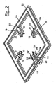
- a modular burner 10 destined for a cooking plate of a cooking appliance comprises a burner base 20 in turn comprising a framework 22 non-limitingly illustrated as square-shaped, a burner base 21 which can be centrally assembled with respect to the framework 22, at least one cover but preferably an outer cover 11 and an inner cover 12 separated and respectively destined for covering the framework 22 and the burner base 21.
- the framework comprises a series of supporting arms 23 which extend radially towards the centre thereof and a burner arm 24 fed by a connection 25 situated along the framework 22.
- the burner arm 24 is therefore "U"-shaped and is equipped with a channel 29' connected to the connection 25 for the feeding of the gas to the whole burner base 21.
- the burner arm 24 also has flame-divider notches 30 situated along the edge of the wings 35 of the "U" to allow the formation of the flame along this section.
- each supporting arm 23 has a seat 31 equipped with a hole 19 suitable for housing the corresponding ends of the burner base 21 and allow it to be fixed by means of screws 15.
- the burner arm 24 has to allow the passage of gas along the channel 29', it has a lower bracket 38 suitable for being connected to a corresponding lower counter-element 37 extending from the burner base 21.
- the framework 22 is also equipped with further holes 19 for fixing the outer cover 11 and inner cover 12.
- the burner base 21 is equipped with radial channels 27 configured so as to correspond to the arms 23, 24 which support them and allow the circulation of gas fed by the channel 29' connected to the connection 25.
- the burner base 21 also comprises a crown 26 having a central aeration opening 28, the channels 27 extend radially from said crown.
- Three of the channels 27 are each equipped at their free end with a bracket 32 with a hole 33 destined for one of the three arms 23.
- the fourth channel 27 is arranged for being connected to the burner arm 24 and has a lower counter-element 37 for the purpose.
- Both the crown 26 and the channels 27 have a "U"-shaped profile with wings 35 and a bottom 36.
- the three channels 27 destined for being connected to the three supporting arms 23 are also equipped with a transversal septum 34 which closes the channel at the end to be inserted in the seat 31.
- the fourth channel 27 destined for connection with the burner arm 24, on the other hand, has a free duct 29 to allow the entry of gas to the burner.
- Flame-divider notches 30 are present along the sides of the wings 35.
- the covers 11 and 12 are provided for the upper closing of the ducts, which can be seal-fixed by means of-screws 15 to be screwed into specific holes 19 correspondingly situated in the framework 22.
- Said covers 11, 12 have upper first and second wings 13 and 13', respectively, for supporting the cooking containers in a raised position with respect to the burner, the first wings 13 extend from the outer cover 11 whereas the second wings extend from the inner cover 12 to support smaller containers.
- the outer cover 11 therefore corresponds to the framework 22, and has holes 14 corresponding to the holes 19 for fixing with screws 15.
- the inner cover 12 corresponds to the burner base 21, in particular it comprises four plates 17 radially extending from a central crown 16 configured so as to correspond to the radial channels 27 and the crown 26 of the burner base, respectively.
- the inner cover 12 also has an opening 18 corresponding to the aeration opening 28 of the burner base.
- the washing of the burner is much more practical with respect to conventional burners, as it is possible to effect said washing in dishwashers, for example, or with suitable solvents suitable for dissolving the crusting.
- the burner according to the invention has advantageous variants.
- Figure 5 illustrates a rounded cover 50 destined for covering the burner base 21.
- the cover is equipped with channels 51 equipped with flame-divider notches 53 along the lower edges 52.
- FIG. 6-8 illustrate a double burner 100 with a small flame and large flame.
- the burner therefore comprises the base 20 connected to a second base 120 destined for a burner with a double crown 121, destined for a burner base with an outer crown 122 and an inner crown 123 connected to each other.
- the base 120 is equipped with supporting arms 126 and at least one burner arm 124 fed by a connection 125.
- the cover 101 of the framework correspondingly has a double dimension for covering both of the frameworks 20, 120 whereas a cover 112 is envisaged of the double-crowned burner forming an outer crown 112 and an inner crown 113, whereas the small burner envisages the cover 20 described above.
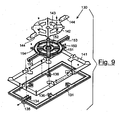
- FIGS 9-12 illustrate a large-flame burner 130, consisting of a burner base 131 correspondingly extended, preferably equipped with two opposite burner arms 134 each having its own feeding connection 135 and four supporting arms 136 arranged centrally.
- the double-crowned burner base 150 has two opposite extended ducts 153 suitable for connection to the two burner arms 134 and four supporting arms 154 corresponding to the arms 136.
- the burner base has an outer crown 151 and an inner crown 152 connected for the gas circulation.
- the burner base and burner crown are closed above by an outer perimetric cover 141 and a double-crowned cover having an outer crown 142 and inner crown 143 and two opposite extended plates 144 suitable for closing the extended ducts 153.
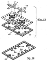
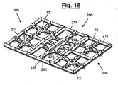
- Figure 13 illustrates another embodiment of a double small-small flame burner 200 in which a single double base 220 equipped with two burner arms 224 allows the assembly of two burners 21, the whole unit being closed above by an outer cover 211 and two inner covers 12 respectively.
- FIGS. 14 and 15 illustrate an oblong burner for a fish pan 250 consisting of a burner base 251 correspondingly extended preferably equipped with two opposite burner arms 254 each having its own feeding connection 255 and six supporting arms 256 arranged centrally.
- the burner base 261 has an oblong crown 262 and two opposite extended ducts 264 suitable for connection to the two burner arms 254 and six supporting arms 263 corresponding to the base arms 256.
- the burner base 251 and burner 261 are respectively closed above by an outer perimetric cover 271 and an oblong cover having an oblong crown 273 and two opposite extended plates 272 suitable for closing the extended ducts 264.
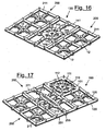
- FIGS 16-18 illustrate different cooling plate compositions using the burners described above, and respectively:
Landscapes
- Engineering & Computer Science (AREA)
- Chemical & Material Sciences (AREA)
- Combustion & Propulsion (AREA)
- Mechanical Engineering (AREA)
- General Engineering & Computer Science (AREA)
- Gas Burners (AREA)
- Control And Other Processes For Unpacking Of Materials (AREA)
- Meat, Egg Or Seafood Products (AREA)
Claims (25)
- Modularer Brenner für eine Kochplatte einer Kochanwendung, umfassend eine Brennerbasis (20), die ihrerseits einen Rahmen (22), eine Brennerbasis (21), zumindest eine Abdeckung (11, 12) zum Abdecken des Rahmens (22) und der Brennerbasis (21) umfasst, dadurch gekennzeichnet, dass die Brennerbasis (21) zentral an dem Rahmen (22) angeordnet werden kann.
- Modularer Brenner nach Anspruch 1, dadurch gekennzeichnet, dass der Brenner eine Außenabdeckung (11) und eine Innenabdeckung (12) aufweist, die getrennt und zum Abdecken des Rahmens (22) bzw. der Brennerbasis (21) bestimmt sind.
- Modularer Brenner nach Anspruch 1, dadurch gekennzeichnet, dass der Rahmen (22) eine Reihe von Trägerarmen (23), die sich radial in Richtung des Zentrums desselben erstrecken, und eine Brennerbasis (24) umfasst, die mit Gas von einer Verbindung (25), die entlang des Rahmens (22) angeordnet ist, gespeist wird.
- Modularer Brenner nach Anspruch 3, dadurch gekennzeichnet, dass der Brenner einen quadratischen Rahmen (22) mit drei Trägerarmen (23), die das Zentrum von drei Seiten des Rahmens verlassen, und einen Brennerarm (24) aufweist, der das Zentrum der vierten Seite verlässt.
- Modularer Brenner nach Anspruch 4, dadurch gekennzeichnet, dass der Brennerarm (24) "U"-förmig mit Flügeln (35) ausgebildet ist und mit einem Kanal (29') ausgestattet ist, der mit der Verbindung (25) für das die gesamte Brennerbasis (21) speisende Gas verbunden ist, wobei der Brennerarm (24) auch Flammenteilerkerben (30) aufweist, die entlang des Randes der Flügel (35) des "U" angeordnet sind.
- Modularer Brenner nach Anspruch 4, dadurch gekennzeichnet, dass der Brennerarm (24) eine untere Halterung (38) aufweist, die zur Verbindung mit einem entsprechenden unteren Gegenelement (37) geeignet ist, das sich von der Brennerbasis (21) erstreckt.
- Modularer Brenner nach Anspruch 6, dadurch gekennzeichnet, dass an dem Ende, das zu dem Inneren des Rahmens weist, jeder Trägerarm (23) einen Sitz (31) aufweist, der mit einem Loch (19) ausgestattet ist, um die entsprechenden Enden der Brennerbasis (21) aufzunehmen und zu ermöglichen, dass diese mittels Schrauben (15) fixiert werden können.
- Modularer Brenner nach Anspruch 1, dadurch gekennzeichnet, dass die Brennerbasis (21) mit radialen Kanälen (27) ausgestattet ist, die derart konfiguriert sind, dass sie mit den Armen (23, 24) übereinstimmen, um durch diese getragen zu werden, und die Zirkulation des Gases zu ermöglichen, das von dem mit der Verbindung (25) verbundenen Kanal (29') gespeist wird.
- Modularer Brenner nach Anspruch 8, dadurch gekennzeichnet, dass die Brennerbasis (21) auch eine Krone (26) aufweist, die mit einer zentralen Belüftungsöffnung (28) ausgestattet ist, wobei sich die Kanäle (27) radial von der Krone erstrecken.
- Modularer Brenner nach Anspruch 9, dadurch gekennzeichnet, dass drei der vier Kanäle (27) jeweils an ihrem eigenen freien Ende mit einer Halterung (32) mit einem Loch (33) ausgestattet sind, das für einen der drei Arme (23) bestimmt ist, und der vierte Kanal (27) zur Verbindung mit dem Brennerarm (24) geeignet ist, der zu diesem Zweck ein unteres Gegenelement (37) aufweist.
- Modularer Brenner nach Anspruch 10, dadurch gekennzeichnet, dass die Krone (26) und die Kanäle (27) ein "U"-förmiges Profil mit Flügeln (35) und einem Boden (36) aufweisen, wobei entlang der Ränder der Flügel (35) Flammenteilerkerben (30) vorhanden sind.
- Modularer Brenner nach Anspruch 10, dadurch gekennzeichnet, dass für den oberen Verschluss der Leitungen Abdeckungen (11, 12) vorhanden sind, die mittels von Schrauben (15) zum Einschrauben in spezifische Löcher (19), die entsprechend in dem Rahmen (22) positioniert sind, abdichtend fixiert werden können.
- Modularer Brenner nach Anspruch 12, dadurch gekennzeichnet, dass über den Abdeckungen (11, 12) ein erster bzw. zweiter Flügel (13, 13') zum Tragen von Kochbehältern in einer erhöhten Position in Bezug auf den Brenner vorhanden sind.
- Modularer Brenner nach Anspruch 13, dadurch gekennzeichnet, dass die Außenabdeckung (11) in Übereinstimmung mit dem Rahmen (22) angeordnet ist und Löcher (14) besitzt, die den Löchern (19) zum Fixieren der Schrauben (15) entsprechen.
- Modularer Brenner nach Anspruch 13, dadurch gekennzeichnet, dass die Innenabdeckung (12) in Übereinstimmung mit der Brennerbasis (21) angeordnet ist, und die vier Platten (17) aufweist, die sich von einer zentralen Krone (16) radial erstrecken, die derart konfiguriert sind, dass sie mit den radialen Kanälen (27) bzw. der Krone (26) der Brennerbasis (21) übereinstimmen.
- Modularer Brenner nach Anspruch 15, dadurch gekennzeichnet, dass die Innenabdeckung (12) auch eine Öffnung (18) besitzt, die mit der Belüftungsöffnung (28) der Brennerbasis übereinstimmt.
- Modularer Brenner nach Anspruch 1, dadurch gekennzeichnet, dass der Brenner eine gerundete Abdeckung (50) umfasst, die zum Abdecken der Brennerbasis (21) bestimmt ist.
- Modularer Brenner nach Anspruch 1, dadurch gekennzeichnet, dass der Brenner in der Form eines Doppelbrenners (100) mit einer kleinen Flamme und einer großen Flamme vorgesehen ist, umfassend, dass die Basis (20) mit einer zweiten Basis (120) verbunden ist, die für einen doppelkronigen Brenner (121) bestimmt ist, der für eine Brennerbasis mit einer Außenkrone (122) und einer Innenkrone (123), die miteinander verbunden sind, bestimmt ist, wobei die Basis (120) mit Trägerarmen (126) und zumindest einem Brennerarm (124) ausgestattet ist, der durch eine Verbindung (125) gespeist wird, wobei die Abdeckung (101) des Rahmens entsprechend eine doppelte Abmessung zum Abdecken beider Rahmen (20, 120) besitzt, während eine Abdeckung (112) des doppelkronigen Brenners vorhanden ist, die eine Außenkrone (112) und eine Innenkrone (113) bildet, während die Abdeckung (12) für den kleinen Brenner (21) vorgesehen ist.
- Modularer Brenner nach Anspruch 1, dadurch gekennzeichnet, dass der Brenner in der Form eines Großflammenbrenners (130) vorgesehen ist, der mit einem Brenner (131) mit entsprechend verlängerter Basis hergestellt ist, der bevorzugt mit zwei gegenüberliegenden Brennerarmen (134), die jeweils mit ihrer eigenen Speiseverbindung (135) ausgestattet sind, und vier Trägerarmen (136) ausgestattet ist, die zentral angeordnet sind, wobei die doppelkronige Brennerbasis (150) zwei sich entgegengesetzt erstreckende Leitungen (153), die zur Verbindung mit den beiden Brennerarmen (134) geeignet sind, und vier Trägerarme (154) besitzt, die mit den Armen (136) übereinstimmen, wobei die Brennerbasis eine Außenkrone (151) und eine Innenkrone (152) aufweist, die für die Gaszirkulation verbunden sind, wobei die Brennerbasis und die Brennerkrone oben durch eine Außenumfangsabdeckung (141) und eine doppelkronige Abdeckung, die eine Außenkrone (142) und eine Innenkrone (143) aufweist, und zwei gegenüberliegende verlängerte Platten (144) geschlossen sind, die zum Schließen der verlängerten Leitungen (153) geeignet sind.
- Modularer Brenner nach Anspruch 1, dadurch gekennzeichnet, dass der Brenner in der Form eines Doppel-Klein-Klein-Flammenbrenners (200) vorgesehen ist, in dem eine einzelne Doppelbasis (220), die mit zwei Brennerarmen (224) ausgestattet ist, den Zusammenbau von zwei Brennern (21) ermöglicht, wobei die gesamte Einheit oben durch eine Außenabdeckung (211) bzw. zwei innere Abdeckungen (12) geschlossen ist.
- Modularer Brenner nach Anspruch 1, dadurch gekennzeichnet, dass der Brenner in der Form eines länglichen Brenners für eine Fischpfanne (250) vorgesehen ist, der mit einer entsprechend verlängerten Brennerbasis (251) hergestellt ist, die bevorzugt mit zwei gegenüberliegenden Brennerarmen (254), die jeweils mit ihrer eigenen Speiseverbindung (255) ausgestattet sind, und sechs Trägerarmen (256) ausgestattet ist, die zentral angeordnet sind, wobei die Brennerbasis (261) eine längliche Krone (262) und zwei sich entgegengesetzt erstreckende Leitungen (264), die zur Verbindung mit den beiden Brennerarmen (254) geeignet sind, und sechs Trägerarme (263) besitzt, die mit den Armen (256) der Basis übereinstimmen, wobei die Brennerbasis (251) und der Brenner (261) oben durch eine Außenumfangsabdeckung (271) und eine längliche Abdeckung, die eine längliche Krone (273) und zwei sich entgegengesetzt erstreckende Platten (272) aufweist, geschlossen sind, die zum Schließen der verlängerten Kanäle (264) geeignet sind.
- Zusammensetzung einer Kochplatte, umfassend einen oder mehrere Brenner gemäß den vorhergehenden Ansprüchen.
- Zusammensetzung einer Kochplatte nach Anspruch 22, dadurch gekennzeichnet, dass sie zwei Doppel-Klein-Flammenseitenbrenner (200) mit einem zentralen Großflammenbrenner (130) umfasst.
- Zusammensetzung einer Kochplatte nach Anspruch 22, dadurch gekennzeichnet, dass sie einen Doppel-Klein-Flammenseitenbrenner (200) mit einem zentralen länglichen Brenner für eine Fischpfanne (250) und einem Doppel-Groß-Klein-Flammenseitenbrenner (100) umfasst.
- Zusammensetzung einer Kochplatte nach Anspruch 22, dadurch gekennzeichnet, dass sie zwei Doppel-Klein-Flammenseitenbrenner (200) mit einem zentralen länglichen Brenner für eine Fischpfanne (250) umfasst.
Applications Claiming Priority (2)
| Application Number | Priority Date | Filing Date | Title |
|---|---|---|---|
| IT000535A ITMI20060535A1 (it) | 2006-03-23 | 2006-03-23 | Bruciatore modulare per piastra di cottura |
| PCT/EP2007/000371 WO2007107195A1 (en) | 2006-03-23 | 2007-01-11 | Modular burner for a cooking plate |
Publications (2)
| Publication Number | Publication Date |
|---|---|
| EP1996869A1 EP1996869A1 (de) | 2008-12-03 |
| EP1996869B1 true EP1996869B1 (de) | 2011-03-09 |
Family
ID=38190827
Family Applications (1)
| Application Number | Title | Priority Date | Filing Date |
|---|---|---|---|
| EP07702825A Not-in-force EP1996869B1 (de) | 2006-03-23 | 2007-01-11 | Modularer brenner für kochplatte |
Country Status (8)
| Country | Link |
|---|---|
| US (1) | US7967004B2 (de) |
| EP (1) | EP1996869B1 (de) |
| CN (1) | CN101427076B (de) |
| AT (1) | ATE501400T1 (de) |
| DE (1) | DE602007013015D1 (de) |
| IT (1) | ITMI20060535A1 (de) |
| RU (1) | RU2411413C2 (de) |
| WO (1) | WO2007107195A1 (de) |
Families Citing this family (20)
| Publication number | Priority date | Publication date | Assignee | Title |
|---|---|---|---|---|
| ITMI20050837A1 (it) * | 2005-05-11 | 2006-11-12 | Enzo Inzaghi | Piano di cottura con distribuzione delle fiamme ottimizzata |
| GB2484272A (en) * | 2010-10-04 | 2012-04-11 | Tim Campbell | Patio heater gas burner |
| ITTO20110078U1 (it) * | 2011-07-29 | 2013-01-30 | Indesit Co Spa | Bruciatore di gas, in particolare per un apparecchio di cottura per alimenti |
| ES2621792T3 (es) * | 2011-11-04 | 2017-07-05 | Electrolux Home Products Corporation N.V. | Conjunto de quemador de gas, placa de cocina de gas y electrodoméstico con quemadores de gas |
| WO2013097986A1 (en) * | 2011-12-26 | 2013-07-04 | Arcelik Anonim Sirketi | A cooker |
| DE102013105874A1 (de) * | 2013-06-06 | 2014-12-11 | Isofrost Gmbh | Gasbrenneranordnung |
| WO2016145746A1 (zh) * | 2015-03-13 | 2016-09-22 | 广东美的厨房电器制造有限公司 | 燃烧器及燃气用具 |
| US9995482B2 (en) * | 2015-11-13 | 2018-06-12 | Haier Us Appliance Solutions, Inc. | Gas burner assembly |
| CN105387490A (zh) * | 2015-11-26 | 2016-03-09 | 王本 | 一种适用于烹饪鱼类的燃气灶 |
| US10401034B2 (en) * | 2016-03-22 | 2019-09-03 | Haier Us Appliance Solutions, Inc. | Illuminated cooktop burner appliance |
| US10393387B2 (en) * | 2016-11-21 | 2019-08-27 | Haier Us Appliance Solutions, Inc. | Gas burner assembly for a cooktop appliance |
| US10641494B2 (en) * | 2016-11-22 | 2020-05-05 | Haier Us Appliance Solutions, Inc. | Cooktop appliance with a gas burner assembly |
| US10612788B2 (en) | 2016-12-15 | 2020-04-07 | Whirlpool Corporation | Gas cooktop and grate for the gas cooktop |
| USD836373S1 (en) | 2016-12-15 | 2018-12-25 | Whirlpool Corporation | Cooktop grate |
| USD837362S1 (en) * | 2017-04-19 | 2019-01-01 | Glen Dimplex Americas Limited | Forked paddle element for an electric fireplace |
| CN111902674A (zh) * | 2018-03-26 | 2020-11-06 | 伊莱克斯家用电器股份公司 | 燃气烹饪组件以及包括该燃气烹饪组件的灶具 |
| EP3546833B1 (de) * | 2018-03-26 | 2021-06-16 | Electrolux Appliances Aktiebolag | Gaskochvorrichtung und kochfeld mit derselben |
| US11268692B2 (en) * | 2018-12-07 | 2022-03-08 | Bsh Home Appliances Corporation | Gas cooking grate with integral burner |
| US20220214046A1 (en) * | 2019-06-26 | 2022-07-07 | BSH Hausgeräte GmbH | Pan support, gas hob and method for producing a pan support |
| EP4062105A4 (de) * | 2020-01-16 | 2023-09-27 | Mamur Teknoloji Sistemleri San. A.S. | Gaskochmulde mit asymmetrischem brennerlayout |
Family Cites Families (44)
| Publication number | Priority date | Publication date | Assignee | Title |
|---|---|---|---|---|
| US560357A (en) * | 1896-05-19 | Gas stove | ||
| US1355933A (en) * | 1916-01-31 | 1920-10-19 | Lewis T Wilcox | Liquid-fuel stove |
| US1649007A (en) * | 1927-02-19 | 1927-11-15 | Lewis T Wilcox | Heat collector |
| US1931517A (en) * | 1930-05-05 | 1933-10-24 | Milwaukee Gas Specialty Co | Lighting device |
| US1889548A (en) * | 1931-08-04 | 1932-11-29 | Superior Coal Comb Company | Grate |
| US2029449A (en) * | 1932-03-14 | 1936-02-04 | Teller Stove Designing Corp | Cooking range construction |
| US2040446A (en) * | 1934-05-31 | 1936-05-12 | Floyd Wells Company | Gas burner |
| US2025458A (en) * | 1934-08-29 | 1935-12-24 | Harry H Graves | Burner |
| US2100292A (en) * | 1936-07-17 | 1937-11-23 | Floyd Wells Company | Burner forming grid |
| US2148777A (en) * | 1937-11-06 | 1939-02-28 | Floyd Wells Company | Gas burner and support therefor |
| US2320754A (en) * | 1938-05-05 | 1943-06-01 | Sherman Jackson Roose Company | Gas burner |
| US2257399A (en) * | 1938-10-20 | 1941-09-30 | Gas Products Corp | Gaseous fuel cookstove |
| US2255349A (en) * | 1939-01-21 | 1941-09-09 | Robert P Sniffen | Burner |
| US2337095A (en) * | 1940-03-08 | 1943-12-21 | American Stove Co | Range |
| US2402429A (en) * | 1940-07-03 | 1946-06-18 | American Stove Co | Range |
| US2300156A (en) * | 1940-08-24 | 1942-10-27 | Bryant Heater Co | Lighter for gas burners |
| US2506483A (en) * | 1944-06-05 | 1950-05-02 | Forrest S Bechtold | Stove-top burner and air shield |
| US2498289A (en) * | 1944-11-04 | 1950-02-21 | American Stove Co | Double ring burner with combined aeration and collection tray |
| US2480046A (en) * | 1945-08-22 | 1949-08-23 | Florence Stove Co | Cooking top |
| US2487720A (en) * | 1947-12-01 | 1949-11-08 | Albert E Miller | Air heating and humidifying gas burning furnace |
| US2654359A (en) * | 1948-05-04 | 1953-10-06 | Florence Stove Co | Gas cookstove with combined top pilot and simmer burner |
| US2632438A (en) * | 1948-12-10 | 1953-03-24 | Chambers Corp | Top pilot cover plate |
| US2862667A (en) * | 1954-10-25 | 1958-12-02 | Roper Corp Geo D | Autoamtic control for range |
| US2861563A (en) * | 1955-05-13 | 1958-11-25 | Roper Corp Geo D | Burner grate construction |
| US3202203A (en) * | 1962-11-16 | 1965-08-24 | Zink Co John | Burner for gaseous fuels |
| US4313416A (en) * | 1979-09-04 | 1982-02-02 | Lau Ka K | Wok burner |
| US4705021A (en) * | 1987-03-05 | 1987-11-10 | The Maytag Company | Gas burner construction |
| IT1273116B (it) | 1994-04-08 | 1997-07-04 | Merloni Elettrodomestici Spa | Piano di cottura domestico, con bruciatori di gas ad assetto variabile |
| IT241062Y1 (it) | 1996-12-10 | 2001-04-20 | Smeg Spa | Piano di cottura con bruciatori fissi abbinati |
| RU13689U1 (ru) * | 1999-11-30 | 2000-05-10 | Глебов Сергей Борисович | Плита бытовая |
| US6132205A (en) * | 2000-01-06 | 2000-10-17 | Harneit; Uwe | Multi-ring sealed gas burner |
| FR2804496B1 (fr) * | 2000-01-28 | 2002-07-19 | Sourdillon Sa | Bruleur a gaz a multiples couronnes de flammes |
| US7322820B2 (en) * | 2001-11-08 | 2008-01-29 | Bsh Home Appliances Corporation | Controlled flame gas burner |
| US6672302B1 (en) * | 2002-07-25 | 2004-01-06 | Wayne/Scott Fetzer Company | Gas burner |
| ES1056041Y (es) * | 2003-11-11 | 2004-06-01 | Fagor S Coop | Quemador de gas de triple corona para placas de coccion. |
| ITMC20040024A1 (it) | 2004-02-13 | 2004-05-13 | So Mi Press Societa Metalli In | Doppio bruciatore per cucine a gas, del tipo a piu' corone concentriche di fiamme |
| ITVE20040031A1 (it) | 2004-07-09 | 2004-10-09 | Ohg Defendi S R L | Bruciatore a piu' settori di fiamme. |
| US20060207588A1 (en) * | 2005-03-18 | 2006-09-21 | Bsh Home Appliances Corporation | Diffusion plate and grate assembly for a gas burner |
| US7650882B2 (en) * | 2005-04-22 | 2010-01-26 | General Electric Company | Pot supports and burner systems including same |
| ITMI20050837A1 (it) * | 2005-05-11 | 2006-11-12 | Enzo Inzaghi | Piano di cottura con distribuzione delle fiamme ottimizzata |
| FR2889293B1 (fr) * | 2005-07-29 | 2009-12-18 | Burner Systems Int Bsi | Bruleur a gaz a multiples couronnes de flammes concentriques |
| US8302593B2 (en) * | 2005-12-30 | 2012-11-06 | General Electric Company | Gas burner assembly including inner and outer burners and methods for implementing same |
| US7871264B2 (en) * | 2006-12-29 | 2011-01-18 | Electrolux Home Products, Inc. | Hub and spoke burner port configuration |
| US7881593B2 (en) * | 2007-11-16 | 2011-02-01 | Cfom Inc. | Gas cooking appliance with removable burners and useable work area |
-
2006
- 2006-03-23 IT IT000535A patent/ITMI20060535A1/it unknown
-
2007
- 2007-01-11 AT AT07702825T patent/ATE501400T1/de not_active IP Right Cessation
- 2007-01-11 US US12/225,086 patent/US7967004B2/en not_active Expired - Fee Related
- 2007-01-11 EP EP07702825A patent/EP1996869B1/de not_active Not-in-force
- 2007-01-11 DE DE602007013015T patent/DE602007013015D1/de active Active
- 2007-01-11 WO PCT/EP2007/000371 patent/WO2007107195A1/en not_active Ceased
- 2007-01-11 RU RU2008137372/03A patent/RU2411413C2/ru not_active IP Right Cessation
- 2007-01-11 CN CN200780014565.3A patent/CN101427076B/zh not_active Expired - Fee Related
Also Published As
| Publication number | Publication date |
|---|---|
| ATE501400T1 (de) | 2011-03-15 |
| ITMI20060535A1 (it) | 2007-09-24 |
| WO2007107195A1 (en) | 2007-09-27 |
| DE602007013015D1 (de) | 2011-04-21 |
| RU2411413C2 (ru) | 2011-02-10 |
| EP1996869A1 (de) | 2008-12-03 |
| US7967004B2 (en) | 2011-06-28 |
| CN101427076B (zh) | 2013-03-20 |
| RU2008137372A (ru) | 2010-04-27 |
| US20090101132A1 (en) | 2009-04-23 |
| CN101427076A (zh) | 2009-05-06 |
Similar Documents
| Publication | Publication Date | Title |
|---|---|---|
| US7967004B2 (en) | Modular burner for a cooking plate | |
| AU2009262766B2 (en) | Cooktop swirl burner | |
| RU2386085C2 (ru) | Варочная поверхность с оптимизированным распределением пламени | |
| US3645249A (en) | Gas cooktop with integral burners | |
| US9492030B2 (en) | Cooking pan provided with exhaust device | |
| US11402101B2 (en) | Cooktop appliance with a gas burner assembly having a thermal break | |
| US7363923B2 (en) | cooking range assembly and monolithic drip pan | |
| CA2538558A1 (en) | Diffusion plate and grate assembly for a gas burner | |
| CN211060193U (zh) | 一种集液构件、燃烧器和具有其的灶具 | |
| WO2008015557A2 (en) | Kitchen appliance for preparing and cooking food | |
| KR100764816B1 (ko) | 전기밥솥의 다용도 밥통 | |
| CN215723386U (zh) | 一种便携式燃气野营炉 | |
| JPH09196393A (ja) | 厨房家具 | |
| EP2513565B1 (de) | Ofen mit einem brennergehäuse | |
| KR102663290B1 (ko) | 배기장치 | |
| CN220069444U (zh) | 一种组合式锅具 | |
| CN223869263U (zh) | 防污通风装置、燃烧器及灶具 | |
| RU2453772C2 (ru) | Газовая варочная поверхность | |
| KR200366744Y1 (ko) | 바람막이 기능을 갖는 가스렌지용 국물받이 | |
| KR20100008491U (ko) | 버너일체형 솥 | |
| ITAN20070036A1 (it) | Piano cottura a tre elementi componibili | |
| WO1991003330A1 (en) | Ejector-type ventilation hood | |
| JPH047789Y2 (de) | ||
| KR200195023Y1 (ko) | 가스레인지의 커버 | |
| JP2025187920A (ja) | 五徳セット及びそれを備えるガスこんろ |
Legal Events
| Date | Code | Title | Description |
|---|---|---|---|
| PUAI | Public reference made under article 153(3) epc to a published international application that has entered the european phase |
Free format text: ORIGINAL CODE: 0009012 |
|
| 17P | Request for examination filed |
Effective date: 20080919 |
|
| AK | Designated contracting states |
Kind code of ref document: A1 Designated state(s): AT BE BG CH CY CZ DE DK EE ES FI FR GB GR HU IE IS IT LI LT LU LV MC NL PL PT RO SE SI SK TR |
|
| GRAP | Despatch of communication of intention to grant a patent |
Free format text: ORIGINAL CODE: EPIDOSNIGR1 |
|
| DAX | Request for extension of the european patent (deleted) | ||
| GRAS | Grant fee paid |
Free format text: ORIGINAL CODE: EPIDOSNIGR3 |
|
| RAP1 | Party data changed (applicant data changed or rights of an application transferred) |
Owner name: STEEL TIME S.P.A. |
|
| GRAA | (expected) grant |
Free format text: ORIGINAL CODE: 0009210 |
|
| AK | Designated contracting states |
Kind code of ref document: B1 Designated state(s): AT BE BG CH CY CZ DE DK EE ES FI FR GB GR HU IE IS IT LI LT LU LV MC NL PL PT RO SE SI SK TR |
|
| REG | Reference to a national code |
Ref country code: GB Ref legal event code: FG4D |
|
| REG | Reference to a national code |
Ref country code: CH Ref legal event code: EP |
|
| REG | Reference to a national code |
Ref country code: IE Ref legal event code: FG4D |
|
| REF | Corresponds to: |
Ref document number: 602007013015 Country of ref document: DE Date of ref document: 20110421 Kind code of ref document: P |
|
| REG | Reference to a national code |
Ref country code: DE Ref legal event code: R096 Ref document number: 602007013015 Country of ref document: DE Effective date: 20110421 |
|
| REG | Reference to a national code |
Ref country code: NL Ref legal event code: VDEP Effective date: 20110309 |
|
| PG25 | Lapsed in a contracting state [announced via postgrant information from national office to epo] |
Ref country code: LT Free format text: LAPSE BECAUSE OF FAILURE TO SUBMIT A TRANSLATION OF THE DESCRIPTION OR TO PAY THE FEE WITHIN THE PRESCRIBED TIME-LIMIT Effective date: 20110309 Ref country code: ES Free format text: LAPSE BECAUSE OF FAILURE TO SUBMIT A TRANSLATION OF THE DESCRIPTION OR TO PAY THE FEE WITHIN THE PRESCRIBED TIME-LIMIT Effective date: 20110620 Ref country code: SE Free format text: LAPSE BECAUSE OF FAILURE TO SUBMIT A TRANSLATION OF THE DESCRIPTION OR TO PAY THE FEE WITHIN THE PRESCRIBED TIME-LIMIT Effective date: 20110309 Ref country code: LV Free format text: LAPSE BECAUSE OF FAILURE TO SUBMIT A TRANSLATION OF THE DESCRIPTION OR TO PAY THE FEE WITHIN THE PRESCRIBED TIME-LIMIT Effective date: 20110309 Ref country code: GR Free format text: LAPSE BECAUSE OF FAILURE TO SUBMIT A TRANSLATION OF THE DESCRIPTION OR TO PAY THE FEE WITHIN THE PRESCRIBED TIME-LIMIT Effective date: 20110610 |
|
| LTIE | Lt: invalidation of european patent or patent extension |
Effective date: 20110309 |
|
| PG25 | Lapsed in a contracting state [announced via postgrant information from national office to epo] |
Ref country code: AT Free format text: LAPSE BECAUSE OF FAILURE TO SUBMIT A TRANSLATION OF THE DESCRIPTION OR TO PAY THE FEE WITHIN THE PRESCRIBED TIME-LIMIT Effective date: 20110309 Ref country code: NL Free format text: LAPSE BECAUSE OF FAILURE TO SUBMIT A TRANSLATION OF THE DESCRIPTION OR TO PAY THE FEE WITHIN THE PRESCRIBED TIME-LIMIT Effective date: 20110309 Ref country code: FI Free format text: LAPSE BECAUSE OF FAILURE TO SUBMIT A TRANSLATION OF THE DESCRIPTION OR TO PAY THE FEE WITHIN THE PRESCRIBED TIME-LIMIT Effective date: 20110309 Ref country code: BG Free format text: LAPSE BECAUSE OF FAILURE TO SUBMIT A TRANSLATION OF THE DESCRIPTION OR TO PAY THE FEE WITHIN THE PRESCRIBED TIME-LIMIT Effective date: 20110609 Ref country code: CY Free format text: LAPSE BECAUSE OF FAILURE TO SUBMIT A TRANSLATION OF THE DESCRIPTION OR TO PAY THE FEE WITHIN THE PRESCRIBED TIME-LIMIT Effective date: 20110309 Ref country code: SI Free format text: LAPSE BECAUSE OF FAILURE TO SUBMIT A TRANSLATION OF THE DESCRIPTION OR TO PAY THE FEE WITHIN THE PRESCRIBED TIME-LIMIT Effective date: 20110309 |
|
| PG25 | Lapsed in a contracting state [announced via postgrant information from national office to epo] |
Ref country code: BE Free format text: LAPSE BECAUSE OF FAILURE TO SUBMIT A TRANSLATION OF THE DESCRIPTION OR TO PAY THE FEE WITHIN THE PRESCRIBED TIME-LIMIT Effective date: 20110309 |
|
| PG25 | Lapsed in a contracting state [announced via postgrant information from national office to epo] |
Ref country code: PT Free format text: LAPSE BECAUSE OF FAILURE TO SUBMIT A TRANSLATION OF THE DESCRIPTION OR TO PAY THE FEE WITHIN THE PRESCRIBED TIME-LIMIT Effective date: 20110711 Ref country code: EE Free format text: LAPSE BECAUSE OF FAILURE TO SUBMIT A TRANSLATION OF THE DESCRIPTION OR TO PAY THE FEE WITHIN THE PRESCRIBED TIME-LIMIT Effective date: 20110309 |
|
| PG25 | Lapsed in a contracting state [announced via postgrant information from national office to epo] |
Ref country code: RO Free format text: LAPSE BECAUSE OF FAILURE TO SUBMIT A TRANSLATION OF THE DESCRIPTION OR TO PAY THE FEE WITHIN THE PRESCRIBED TIME-LIMIT Effective date: 20110309 Ref country code: SK Free format text: LAPSE BECAUSE OF FAILURE TO SUBMIT A TRANSLATION OF THE DESCRIPTION OR TO PAY THE FEE WITHIN THE PRESCRIBED TIME-LIMIT Effective date: 20110309 Ref country code: CZ Free format text: LAPSE BECAUSE OF FAILURE TO SUBMIT A TRANSLATION OF THE DESCRIPTION OR TO PAY THE FEE WITHIN THE PRESCRIBED TIME-LIMIT Effective date: 20110309 Ref country code: IS Free format text: LAPSE BECAUSE OF FAILURE TO SUBMIT A TRANSLATION OF THE DESCRIPTION OR TO PAY THE FEE WITHIN THE PRESCRIBED TIME-LIMIT Effective date: 20110709 |
|
| PLBE | No opposition filed within time limit |
Free format text: ORIGINAL CODE: 0009261 |
|
| STAA | Information on the status of an ep patent application or granted ep patent |
Free format text: STATUS: NO OPPOSITION FILED WITHIN TIME LIMIT |
|
| 26N | No opposition filed |
Effective date: 20111212 |
|
| PG25 | Lapsed in a contracting state [announced via postgrant information from national office to epo] |
Ref country code: PL Free format text: LAPSE BECAUSE OF FAILURE TO SUBMIT A TRANSLATION OF THE DESCRIPTION OR TO PAY THE FEE WITHIN THE PRESCRIBED TIME-LIMIT Effective date: 20110309 Ref country code: DK Free format text: LAPSE BECAUSE OF FAILURE TO SUBMIT A TRANSLATION OF THE DESCRIPTION OR TO PAY THE FEE WITHIN THE PRESCRIBED TIME-LIMIT Effective date: 20110309 |
|
| REG | Reference to a national code |
Ref country code: DE Ref legal event code: R097 Ref document number: 602007013015 Country of ref document: DE Effective date: 20111212 |
|
| PGFP | Annual fee paid to national office [announced via postgrant information from national office to epo] |
Ref country code: IT Payment date: 20120123 Year of fee payment: 6 |
|
| PG25 | Lapsed in a contracting state [announced via postgrant information from national office to epo] |
Ref country code: MC Free format text: LAPSE BECAUSE OF NON-PAYMENT OF DUE FEES Effective date: 20120131 |
|
| REG | Reference to a national code |
Ref country code: CH Ref legal event code: PL |
|
| GBPC | Gb: european patent ceased through non-payment of renewal fee |
Effective date: 20120111 |
|
| REG | Reference to a national code |
Ref country code: FR Ref legal event code: ST Effective date: 20120928 |
|
| REG | Reference to a national code |
Ref country code: IE Ref legal event code: MM4A |
|
| PG25 | Lapsed in a contracting state [announced via postgrant information from national office to epo] |
Ref country code: DE Free format text: LAPSE BECAUSE OF NON-PAYMENT OF DUE FEES Effective date: 20120801 Ref country code: GB Free format text: LAPSE BECAUSE OF NON-PAYMENT OF DUE FEES Effective date: 20120111 Ref country code: LI Free format text: LAPSE BECAUSE OF NON-PAYMENT OF DUE FEES Effective date: 20120131 Ref country code: CH Free format text: LAPSE BECAUSE OF NON-PAYMENT OF DUE FEES Effective date: 20120131 |
|
| REG | Reference to a national code |
Ref country code: DE Ref legal event code: R119 Ref document number: 602007013015 Country of ref document: DE Effective date: 20120801 |
|
| PG25 | Lapsed in a contracting state [announced via postgrant information from national office to epo] |
Ref country code: FR Free format text: LAPSE BECAUSE OF NON-PAYMENT OF DUE FEES Effective date: 20120131 |
|
| PG25 | Lapsed in a contracting state [announced via postgrant information from national office to epo] |
Ref country code: IE Free format text: LAPSE BECAUSE OF NON-PAYMENT OF DUE FEES Effective date: 20120111 |
|
| PG25 | Lapsed in a contracting state [announced via postgrant information from national office to epo] |
Ref country code: TR Free format text: LAPSE BECAUSE OF FAILURE TO SUBMIT A TRANSLATION OF THE DESCRIPTION OR TO PAY THE FEE WITHIN THE PRESCRIBED TIME-LIMIT Effective date: 20110309 |
|
| PG25 | Lapsed in a contracting state [announced via postgrant information from national office to epo] |
Ref country code: LU Free format text: LAPSE BECAUSE OF NON-PAYMENT OF DUE FEES Effective date: 20120111 |
|
| PG25 | Lapsed in a contracting state [announced via postgrant information from national office to epo] |
Ref country code: HU Free format text: LAPSE BECAUSE OF FAILURE TO SUBMIT A TRANSLATION OF THE DESCRIPTION OR TO PAY THE FEE WITHIN THE PRESCRIBED TIME-LIMIT Effective date: 20070111 |
|
| PG25 | Lapsed in a contracting state [announced via postgrant information from national office to epo] |
Ref country code: IT Free format text: LAPSE BECAUSE OF NON-PAYMENT OF DUE FEES Effective date: 20140111 |