EP1996889B1 - Echangeur de chaleur à plaques, procédé de fabrication de celui-ci et utilisation de celui-ci - Google Patents
Echangeur de chaleur à plaques, procédé de fabrication de celui-ci et utilisation de celui-ci Download PDFInfo
- Publication number
- EP1996889B1 EP1996889B1 EP07723516A EP07723516A EP1996889B1 EP 1996889 B1 EP1996889 B1 EP 1996889B1 EP 07723516 A EP07723516 A EP 07723516A EP 07723516 A EP07723516 A EP 07723516A EP 1996889 B1 EP1996889 B1 EP 1996889B1
- Authority
- EP
- European Patent Office
- Prior art keywords
- heat exchanger
- plates
- plate heat
- plate
- channels
- Prior art date
- Legal status (The legal status is an assumption and is not a legal conclusion. Google has not performed a legal analysis and makes no representation as to the accuracy of the status listed.)
- Not-in-force
Links
- 238000004519 manufacturing process Methods 0.000 title claims abstract description 17
- 238000000034 method Methods 0.000 title claims abstract description 16
- 239000012530 fluid Substances 0.000 claims abstract description 39
- 238000009792 diffusion process Methods 0.000 claims abstract description 9
- 238000003466 welding Methods 0.000 claims abstract description 9
- 229910010293 ceramic material Inorganic materials 0.000 claims abstract description 8
- 229910010271 silicon carbide Inorganic materials 0.000 claims description 28
- HBMJWWWQQXIZIP-UHFFFAOYSA-N silicon carbide Chemical compound [Si+]#[C-] HBMJWWWQQXIZIP-UHFFFAOYSA-N 0.000 claims description 28
- 239000000919 ceramic Substances 0.000 claims description 19
- 238000012546 transfer Methods 0.000 claims description 14
- 238000009826 distribution Methods 0.000 claims description 9
- 239000002245 particle Substances 0.000 claims description 8
- 230000002902 bimodal effect Effects 0.000 claims description 7
- OKTJSMMVPCPJKN-UHFFFAOYSA-N Carbon Chemical compound [C] OKTJSMMVPCPJKN-UHFFFAOYSA-N 0.000 claims description 5
- 239000010439 graphite Substances 0.000 claims description 5
- 229910002804 graphite Inorganic materials 0.000 claims description 5
- 229910052581 Si3N4 Inorganic materials 0.000 claims description 4
- HQVNEWCFYHHQES-UHFFFAOYSA-N silicon nitride Chemical compound N12[Si]34N5[Si]62N3[Si]51N64 HQVNEWCFYHHQES-UHFFFAOYSA-N 0.000 claims description 4
- 229910052580 B4C Inorganic materials 0.000 claims description 3
- INAHAJYZKVIDIZ-UHFFFAOYSA-N boron carbide Chemical compound B12B3B4C32B41 INAHAJYZKVIDIZ-UHFFFAOYSA-N 0.000 claims description 3
- 239000000835 fiber Substances 0.000 claims description 3
- 239000011261 inert gas Substances 0.000 claims description 2
- 230000002093 peripheral effect Effects 0.000 claims 3
- 239000000126 substance Substances 0.000 claims 1
- 239000000463 material Substances 0.000 description 25
- 238000013461 design Methods 0.000 description 12
- 238000005304 joining Methods 0.000 description 8
- 230000007797 corrosion Effects 0.000 description 6
- 238000005260 corrosion Methods 0.000 description 6
- 239000002609 medium Substances 0.000 description 6
- 238000010276 construction Methods 0.000 description 5
- 229910003465 moissanite Inorganic materials 0.000 description 4
- 230000015572 biosynthetic process Effects 0.000 description 3
- 239000007789 gas Substances 0.000 description 3
- 229910000679 solder Inorganic materials 0.000 description 3
- 238000005266 casting Methods 0.000 description 2
- 238000006243 chemical reaction Methods 0.000 description 2
- 238000009833 condensation Methods 0.000 description 2
- 230000005494 condensation Effects 0.000 description 2
- 238000002425 crystallisation Methods 0.000 description 2
- 230000008025 crystallization Effects 0.000 description 2
- 230000000694 effects Effects 0.000 description 2
- 230000008020 evaporation Effects 0.000 description 2
- 238000001704 evaporation Methods 0.000 description 2
- 238000010438 heat treatment Methods 0.000 description 2
- 238000007731 hot pressing Methods 0.000 description 2
- 238000003475 lamination Methods 0.000 description 2
- 239000007788 liquid Substances 0.000 description 2
- 238000012423 maintenance Methods 0.000 description 2
- 239000007769 metal material Substances 0.000 description 2
- 239000011226 reinforced ceramic Substances 0.000 description 2
- 238000007789 sealing Methods 0.000 description 2
- 229910052710 silicon Inorganic materials 0.000 description 2
- 239000010703 silicon Substances 0.000 description 2
- 238000005245 sintering Methods 0.000 description 2
- XLYOFNOQVPJJNP-UHFFFAOYSA-N water Substances O XLYOFNOQVPJJNP-UHFFFAOYSA-N 0.000 description 2
- 229910000831 Steel Inorganic materials 0.000 description 1
- RTAQQCXQSZGOHL-UHFFFAOYSA-N Titanium Chemical compound [Ti] RTAQQCXQSZGOHL-UHFFFAOYSA-N 0.000 description 1
- 239000012736 aqueous medium Substances 0.000 description 1
- 239000011230 binding agent Substances 0.000 description 1
- 230000003197 catalytic effect Effects 0.000 description 1
- 238000000576 coating method Methods 0.000 description 1
- 239000002131 composite material Substances 0.000 description 1
- 238000001816 cooling Methods 0.000 description 1
- 238000012938 design process Methods 0.000 description 1
- 238000005553 drilling Methods 0.000 description 1
- 239000013536 elastomeric material Substances 0.000 description 1
- 238000004049 embossing Methods 0.000 description 1
- 239000011521 glass Substances 0.000 description 1
- 231100001261 hazardous Toxicity 0.000 description 1
- 238000005470 impregnation Methods 0.000 description 1
- 230000008595 infiltration Effects 0.000 description 1
- 238000001764 infiltration Methods 0.000 description 1
- 238000007689 inspection Methods 0.000 description 1
- 238000005259 measurement Methods 0.000 description 1
- 229910052751 metal Inorganic materials 0.000 description 1
- 239000002184 metal Substances 0.000 description 1
- 239000010445 mica Substances 0.000 description 1
- 229910052618 mica group Inorganic materials 0.000 description 1
- 238000001000 micrograph Methods 0.000 description 1
- 238000000386 microscopy Methods 0.000 description 1
- 238000003801 milling Methods 0.000 description 1
- 238000002156 mixing Methods 0.000 description 1
- 238000001556 precipitation Methods 0.000 description 1
- 238000003825 pressing Methods 0.000 description 1
- 230000001737 promoting effect Effects 0.000 description 1
- 230000001681 protective effect Effects 0.000 description 1
- 239000003566 sealing material Substances 0.000 description 1
- 238000005475 siliconizing Methods 0.000 description 1
- 238000005476 soldering Methods 0.000 description 1
- 239000010959 steel Substances 0.000 description 1
- 229910052715 tantalum Inorganic materials 0.000 description 1
- GUVRBAGPIYLISA-UHFFFAOYSA-N tantalum atom Chemical compound [Ta] GUVRBAGPIYLISA-UHFFFAOYSA-N 0.000 description 1
- 239000010936 titanium Substances 0.000 description 1
- 229910052719 titanium Inorganic materials 0.000 description 1
- 230000009466 transformation Effects 0.000 description 1
- 238000000844 transformation Methods 0.000 description 1
Images


Classifications
-
- F—MECHANICAL ENGINEERING; LIGHTING; HEATING; WEAPONS; BLASTING
- F28—HEAT EXCHANGE IN GENERAL
- F28D—HEAT-EXCHANGE APPARATUS, NOT PROVIDED FOR IN ANOTHER SUBCLASS, IN WHICH THE HEAT-EXCHANGE MEDIA DO NOT COME INTO DIRECT CONTACT
- F28D9/00—Heat-exchange apparatus having stationary plate-like or laminated conduit assemblies for both heat-exchange media, the media being in contact with different sides of a conduit wall
- F28D9/0031—Heat-exchange apparatus having stationary plate-like or laminated conduit assemblies for both heat-exchange media, the media being in contact with different sides of a conduit wall the conduits for one heat-exchange medium being formed by paired plates touching each other
- F28D9/0043—Heat-exchange apparatus having stationary plate-like or laminated conduit assemblies for both heat-exchange media, the media being in contact with different sides of a conduit wall the conduits for one heat-exchange medium being formed by paired plates touching each other the plates having openings therein for circulation of at least one heat-exchange medium from one conduit to another
- F28D9/005—Heat-exchange apparatus having stationary plate-like or laminated conduit assemblies for both heat-exchange media, the media being in contact with different sides of a conduit wall the conduits for one heat-exchange medium being formed by paired plates touching each other the plates having openings therein for circulation of at least one heat-exchange medium from one conduit to another the plates having openings therein for both heat-exchange media
-
- F—MECHANICAL ENGINEERING; LIGHTING; HEATING; WEAPONS; BLASTING
- F28—HEAT EXCHANGE IN GENERAL
- F28F—DETAILS OF HEAT-EXCHANGE AND HEAT-TRANSFER APPARATUS, OF GENERAL APPLICATION
- F28F13/00—Arrangements for modifying heat-transfer, e.g. increasing, decreasing
- F28F13/06—Arrangements for modifying heat-transfer, e.g. increasing, decreasing by affecting the pattern of flow of the heat-exchange media
- F28F13/12—Arrangements for modifying heat-transfer, e.g. increasing, decreasing by affecting the pattern of flow of the heat-exchange media by creating turbulence, e.g. by stirring, by increasing the force of circulation
-
- F—MECHANICAL ENGINEERING; LIGHTING; HEATING; WEAPONS; BLASTING
- F28—HEAT EXCHANGE IN GENERAL
- F28F—DETAILS OF HEAT-EXCHANGE AND HEAT-TRANSFER APPARATUS, OF GENERAL APPLICATION
- F28F21/00—Constructions of heat-exchange apparatus characterised by the selection of particular materials
- F28F21/04—Constructions of heat-exchange apparatus characterised by the selection of particular materials of ceramic; of concrete; of natural stone
-
- F—MECHANICAL ENGINEERING; LIGHTING; HEATING; WEAPONS; BLASTING
- F28—HEAT EXCHANGE IN GENERAL
- F28F—DETAILS OF HEAT-EXCHANGE AND HEAT-TRANSFER APPARATUS, OF GENERAL APPLICATION
- F28F3/00—Plate-like or laminated elements; Assemblies of plate-like or laminated elements
- F28F3/02—Elements or assemblies thereof with means for increasing heat-transfer area, e.g. with fins, with recesses, with corrugations
- F28F3/04—Elements or assemblies thereof with means for increasing heat-transfer area, e.g. with fins, with recesses, with corrugations the means being integral with the element
- F28F3/048—Elements or assemblies thereof with means for increasing heat-transfer area, e.g. with fins, with recesses, with corrugations the means being integral with the element in the form of ribs integral with the element or local variations in thickness of the element, e.g. grooves, microchannels
-
- F—MECHANICAL ENGINEERING; LIGHTING; HEATING; WEAPONS; BLASTING
- F28—HEAT EXCHANGE IN GENERAL
- F28F—DETAILS OF HEAT-EXCHANGE AND HEAT-TRANSFER APPARATUS, OF GENERAL APPLICATION
- F28F2250/00—Arrangements for modifying the flow of the heat exchange media, e.g. flow guiding means; Particular flow patterns
- F28F2250/04—Communication passages between channels
-
- F—MECHANICAL ENGINEERING; LIGHTING; HEATING; WEAPONS; BLASTING
- F28—HEAT EXCHANGE IN GENERAL
- F28F—DETAILS OF HEAT-EXCHANGE AND HEAT-TRANSFER APPARATUS, OF GENERAL APPLICATION
- F28F2250/00—Arrangements for modifying the flow of the heat exchange media, e.g. flow guiding means; Particular flow patterns
- F28F2250/10—Particular pattern of flow of the heat exchange media
- F28F2250/102—Particular pattern of flow of the heat exchange media with change of flow direction
Definitions
- the invention relates to a plate heat exchanger of a plurality of plates, preferably of sintered ceramic material, a method for producing such a plate heat exchanger and the use of such a plate heat exchanger as a high-temperature heat exchanger and or for use with corrosive media, as well as a reactor.
- FR-A-2314461 describes a plate heat exchanger according to the preamble of patent claim 1.
- Heat exchangers are particularly effective heat transfer between two separately flowing media, that is they should transfer as much heat as possible with as little exchange surface. At the same time they should oppose the material flows only a small resistance, so that the least possible energy has to be expended for the operation of the pumps used for promotion. If highly aggressive or corrosive media, possibly even at elevated temperatures of more than 200 ° C are passed through the heat exchanger, all materials in contact with the medium in the heat exchanger must be sufficiently resistant to corrosion. In addition to the replacement surfaces, this includes all seals and bushings. In addition, the design of heat exchangers should be designed so that, if necessary, a residue-free emptying of the heat exchanger is easily possible, for example for maintenance.
- Plate heat exchangers are a special design of heat exchangers. They are characterized by a particularly compact design.
- the plates of a plate heat exchanger generally have an embossed or corrugated structure, often called herringbone pattern or chevron pattern, in the region of the exchange surface.
- the embossing causes the medium flowing in the gap between two adjacent plates to become highly entangled, thereby promoting heat transfer.
- the medium is opposed by such a structure, a relatively low flow resistance. An effective heat transfer with the lowest possible pressure loss is so largely met.
- the plates are usually at the edges loosely on each other and are separated by seals. Since plastic seals can only be used up to temperatures of 300 ° C maximum, heat exchangers with plates made of metallic materials for higher operating temperatures or pressures solder or weld the plates together at the edges.
- the gap between two adjacent plates each forms a sealed chamber.
- the volume of the chambers together with the plate stamping decides decisively on pressure loss and efficiency in heat transfer.
- a large chamber volume is both useful and therefore to strive for.
- an operating risk is also accepted. If no support segments are used in the chambers, it can easily lead to a plate break in the construction of an unforeseen high differential pressure between adjacent chambers to a strong deformation of the metal plates or in the case of brittle materials.
- Heat exchanger plates of this form are made of metallic materials, in particular corrosion-resistant steels, titanium or tantalum. Graphite is also used commercially.
- Sintered SiC ceramic is a universally corrosion resistant, yet brittle, material that is free of metallic silicon, in contrast to silicon-infiltrated silicon carbide (SiSiC).
- SiSiC silicon-infiltrated silicon carbide
- SSiC is ideally suited as a material for the exchange surface of heat exchangers due to its very high thermal conductivity.
- SSiC can also be used at high temperatures of well over 1,000 ° C.
- SSiC is also corrosion-resistant in hot water or strongly basic media.
- SSiC sintered SiC ceramics
- the DE 28 41 571 C2 describes a heat exchanger made of ceramic material with L-shaped media guide, wherein preferably Siinfiltrator SiC ceramic (SiSiC) or silicon nitride are used as materials. These materials are disadvantageous in that they are not universally resistant to corrosion. In hot water or strongly basic media, the metallic silicon used for infiltration and sealing in the SiSiC as binder phase dissolves. Leakage currents and loss of strength are the result. With silicon nitride, the grain boundaries are dissolved relatively quickly and the surface is gradually decomposed.
- SiSiC SiC ceramic
- silicon nitride silicon nitride
- EP 1 544 565 A2 the use of fiber reinforced ceramic or SiC especially for the plates of a high temperature plate heat exchanger.
- the channel structure of the plates described therein has fins or ribs and is specially designed for the flow of hot gases, in particular for gas turbines.
- the efficiency would not be good and the pressure loss too high.
- the plate heat exchanger will continue to be produced by film casting and joined by soldering. However, solder joints are always weak points when used with corrosive media, so that such a heat exchanger for use with highly corrosive media, such as alkalis, is not suitable.
- the EP 0 074 471 B1 describes a manufacturing method for a ceramic plate heat exchanger by means of film casting and lamination.
- the lamination process is specifically focused on SiSiC as the material and liquid siliconizing in the manufacturing process.
- FIG. 2 This patent shows an embodiment of a gas-heating heat exchanger, in which baffles are provided perpendicular to the flow direction, which should effect a uniform temperature distribution in the flow channels.
- baffles are provided perpendicular to the flow direction, which should effect a uniform temperature distribution in the flow channels.
- the heat transfer performance and the pressure loss in this heat exchanger are not yet satisfactory.
- the invention is therefore based on the object to provide a plate heat exchanger with improved heat transfer performance and reduced pressure loss, which is also suitable for use at high temperatures and / or with corrosive media if necessary. Furthermore, a method for producing such a heat exchanger is to be specified.
- the invention thus relates to a plate heat exchanger of a plurality of plates, in which fluid flow guide channels are formed as a channel system so that there is a substantially meandering course of the fluid flow over the surface of the respective plate, wherein the side walls of the guide channels a plurality of openings have, which lead to a turbulence of the fluid flow.
- the invention further relates to a method for producing such a plate heat exchanger, wherein the individual plates are stacked and connected to each other by means of circumferential seals.
- the invention also relates to a method for producing such a plate heat exchanger, wherein the individual plates are stacked and joined in a diffusion welding process in the presence of a protective gas atmosphere or in a vacuum at a temperature of at least 1,600 ° C and optionally with application of a load to form a seamless monolithic block ,
- the plate heat exchanger according to the invention is suitable as a high-temperature heat exchanger and / or for use with corrosive media.
- the plate heat exchanger according to the invention can also be used as a reactor with at least two separate fluid circuits.
- the plate heat exchanger according to the invention is suitable as a reactor, wherein in addition one or more reactor plates are provided between the plates, wherein the reactor plates have a different channel system from the plates.
- the fluid flow guide channels are formed as a channel system so that a substantially meandering course of the fluid flow over the surface of the plate results, the side walls of the guide channels having a plurality of interruptions or openings, leading to a Turbulence of the fluid flow lead.
- a further advantage of the design of the plates according to the invention is that feed and discharge openings for the fluid streams, for example in the form of bores, can already be integrated into the plates.
- the heat transfer in a plate heat exchanger according to the invention is compared to plate heat exchangers of the prior art by about 5 to 30% higher and the pressure loss is up to 30% lower.
- the pressure loss is an important criterion in the design of heat exchangers, because thus the required pump power can be reduced accordingly.
- the plate heat exchanger according to the invention has a structure in which a plurality of plates, preferably of sintered ceramic material, are stacked on each other.
- Sintered silicon carbide (SSiC), fiber-reinforced silicon carbide, silicon nitride or combinations thereof are particularly suitable as the sintered ceramic material, with SSiC being particularly preferred.
- SSiC with a bimodal particle size distribution, which optionally up to 35 vol .-% of other material components, such as graphite.
- Boron carbide or other ceramic particles can be used, since this material is particularly well suited for Diffussionsbinden in a hot pressing process (diffusion welding).
- the sintered silicon carbide having a bimodal grain size distribution comprises 50 to 90% by volume of prismatic, platelet-shaped SiC crystallites having a length of 100 to 1,500 ⁇ m and 10 to 50% by volume of prismatic, platelet-shaped SiC crystallites of 5 to less than 5 100 ⁇ m.
- the measurement of the grain size or the length of the SiC crystallites can be determined by light microscopy micrographs, for example with the aid of an image evaluation program, which determines the maximum Feret's diameter of a grain.
- the guide channels in the plates are connected to a first feed opening and a first discharge opening for a first fluid. Furthermore, a second supply opening and a second discharge opening for a second fluid for supplying an adjacent plate may be provided, these openings may be provided in a simple manner by drilling.
- a plate of a first plate type comprises a channel system for a first fluid and an adjacent plate of a second plate type a channel system for a second fluid.
- the first-disk-type disks and the second-disk-type disks may be sequenced in any order to allow for variable speed adjustment.
- the plates connected in parallel or in series are doubled or tripled by one of the two circuits of the heat exchanger in order to allow the material flow to be passed through the plates at a defined speed. This results in stacking sequences of the heat exchanger plates, for example, according to A-BB-A-BB ... or A-BBB-A-BBB ...
- the inventive design of the heat exchanger plates but also allows a so-called two or more common driving style.
- the plates of a circuit instead of parallel connected in series. This is the medium flowing through a longer distance for heating or cooling available.
- the channel system of the plates has a mirror symmetry.
- This mirror-symmetric design allows plates to be alternately stacked 180 ° apart, so that the feed openings are alternately left and right.
- By this arrangement can be constructed with a single design for all plates a heat exchanger, which offers advantages from a production point of view.
- At least two separate channel systems may be provided for different fluids between which heat transfer is to take place.
- the different fluids are guided in counterflow in separate channel systems.
- the plates used according to the invention preferably have a base thickness in the range of 0.2 to 20 mm, particularly preferably about 3 mm.
- the fluid or material flow in an exchange surface of a plate is guided in a meandering manner according to the channel system according to the invention in order to allow the longest possible residence time.
- the side walls or guide walls of the guide channels in the exchange surface have, measured from the plate base, preferably a height in the range of 0.2-30 mm, more preferably 0.2-10 mm, and particularly preferably 0.2-5 mm.
- the trained as webs sidewalls of the guide channels can be produced by milling, but can also be made by near-net shape pressing.
- the side walls of the guide channels have at defined locations interruptions or openings, which preferably have a width of 0.2-20 mm, more preferably 2-5 mm.
- These breakthroughs cause a high turbulence of the fluid flow and allow for the substantially meandering flow pattern high and improved heat transfer efficiency.
- these breakthroughs allow a significant reduction in the conventional plate heat exchangers high pressure loss. Due to the number and width of the apertures, the pressure loss can be adjusted in the desired manner. The breakthroughs also serve to ensure that the heat exchanger can be completely emptied when installed vertically.
- the perforated side walls of the guide channels also act as support points and avoid pressure differences in an undesirable deformation of the plates and also prevent a plate breakage.
- the individual plates are stacked and connected by means of circumferential seals.
- seals For this purpose, customary plastic gaskets, which can be used up to temperatures of about 300 ° C are suitable.
- the construction connected by seals is very inexpensive and then particularly advantageous if the heat exchanger has to be dismantled and cleaned for inspection purposes.
- the individual plates are stacked and joined together to form an seamless monolithic block.
- This monolithic construction in which the panels are sealed without seams via seam-free joining, is particularly advantageous for high temperature applications and environmentally hazardous or corrosive media applications.
- the plate heat exchanger according to the invention, at least two of the plates are stacked and joined together to form an seamless monolithic block and at least two such monolithic blocks are connected to each other by means of circumferential seals.
- This so-called semi-sealed embodiment may be particularly useful when using corrosive media in a material cycle and from the tendency to deposit formation media in the other material cycle.
- the plates for the corrosive medium according to the invention sintered together at least in pairs and stacked the monolithic plate blocks thus obtained by suitable plastic seals, for example made of elastomeric material, sealed.
- This type of plate heat exchanger can always be disassembled, for example, to clean the sealed chambers of the deposit formation.
- the individual plates are stacked and subjected to diffusion welding in the presence of an inert gas atmosphere or under vacuum at a temperature of at least 1,600 ° C, preferably above 1,800 ° C, more preferably above 2,000 ° C and optionally with application of a Load joined to a seamless monolithic block, wherein the components to be joined preferably undergo a plastic deformation in the direction of force application of less than 5%, more preferably less than 1%.
- SSiC sintered SiC
- SSiC sintered SiC
- SSiC coarse-grained SSiC with a bimodal as mentioned above Grain size distribution, which up to 35 vol .-% of other material components, such as graphite.
- Boron carbide or other ceramic particles may contain.
- the resistance to plastic deformation in the high temperature range is referred to in material science with high temperature creep resistance.
- the so-called creep rate is used.
- the creep rate of the ceramic plates to be joined can be used as a central parameter in order to minimize the plastic deformation in a joining process for seamless joining of the sintered ceramic plates.
- Most commercially available sintered SiC materials have structures with a monomodal particle size distribution and a particle size of about 5 ⁇ m. They thus have a sufficiently high sintering activity at joining temperatures of more than 1,700 ° C, but have low creep resistance for low-deformation joining. Therefore, hitherto, in the diffusion welding of such components, high plastic deformation has always been observed. Because the creep resistance of the SSiC materials is generally not very different, creep rate has not heretofore been considered as a useful variable parameter for SSiC joining.
- the ceramic plates to be joined preferably consist of an SSiC material whose creep rate in the joining process is always less than 2 ⁇ 10 -4 1 / s, preferably always less than 8 ⁇ 10 -5 l / s, particularly preferably always less than 2 x 10 -5 1 / s.
- a load of more than 10 kPa, particularly preferably more than 1 MPa, and more preferably more than 10 MPa, is preferably applied, the temperature-holding time at a temperature of at least 1,600 ° C. preferably having a duration of 10 minutes, particularly preferably Exceeds 30 minutes.
- the manufacturing method according to the invention can thus plate heat exchanger, in which previously the seals or solder joints the weak points
- the plate heat exchangers made of sintered SiC ceramics thus produced have an extremely high temperature and corrosion resistance.
- the plate heat exchanger with heat exchanger plates designed according to the invention is also suitable as a reactor, for example for evaporation and condensation, but also for other phase transformations, such as, for example, for targeted crystallization processes.
- a reactor for example for evaporation and condensation, but also for other phase transformations, such as, for example, for targeted crystallization processes.
- reactor plates For a particularly effective use as a reactor, it is expedient to install reactor plates between the heat exchanger plates designed according to the invention, in which case the heat exchanger plates serve to control the temperature of the reactor plates.
- the reactor plates can have different geometries.
- For a controlled residence time and defined precipitation reaction, such as for targeted crystallization processes it is for example advantageous to use reactor plates with continuous straight channels.
- channel structures are used, with which the material flows are supplied to each other in a defined region of the reactor plate and mixed intensively.
- the reactor plates may also have suitable catalytic coatings that specifically accelerate a chemical reaction.
- the plate heat exchanger further comprises a ceramic or metallic Anflanschsystem for the supply and discharge of fluids on the top and / or bottom (lid and / or bottom) of the plate heat exchanger.
- a mica-based sealing material for the sealing of the Flange system is preferably used for high-temperature applications.
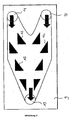
- a plate 1 which can be used according to the invention has a channel system formed by guide channels 2, which allows a substantially meandering course of the fluid flow over the surface of the plate.
- the side walls 3 of the guide channels 2 consist in this figure of webs with a width of 3 mm, which have a plurality of apertures 4 with a width of 3.5 mm.
- the plate further has a first feed opening 5 and a first discharge opening 6 for a fluid flow, each in the form of a bore with a radius of 30 mm.
- a second feed opening 7 and a second discharge opening 8, which serve as a passage for supplying a neighboring chamber with another medium, are provided.
- the second feed opening and second discharge opening each consist of holes with a radius of 32 mm.
- the total length of the plate in this embodiment is 500 mm and its width is 200 mm.
- the channel system in this embodiment has a mirror symmetry. This mirror symmetry makes it possible for the plates to be alternately stacked against each other rotated through 180 °, so that the feed openings are alternately once on the left and once on the right.
- the Figure 2 shows a reactor plate 9 can be used according to the invention with a first feed opening 10 for a first fluid flow and a second Feed port 11 for a second fluid stream.
- the two fluid streams are then supplied to each other through the baffles 12 so that an intensive mixing of the fluid streams takes place.
- the mixed stream is then removed via the discharge opening 13.
- Figures 3a and 3b show how metallic flanges are clamped to a ceramic monolith.
- a ceramic heat exchanger is used with heat exchanger plates of the type illustration 1 produced.
- the plates have a length of 500 mm, a bottom thickness of 3 mm and guide channels with a height of 3.5 mm.
- the side walls have openings of a width of 3 mm.
- For the production of the heat exchanger block four heat exchanger plates according to the invention and a cover plate are used, wherein all components consist of sintered silicon carbide with bimodal particle size distribution. All ceramic panels are stacked and bonded together to form a monolithic block.
- the plates are arranged in the block so that two streams can exchange heat in countercurrent.
- the hermetically sealed sintered silicon carbide heat exchanger block is provided with four 50mm internal diameter flanges.
- the heat exchanger apparatus is operated with aqueous media. At a flow rate of 1000 l / h, a pressure drop of 100 mbar occurs and 6000 W / m 2 K are transferred.
Landscapes
- Engineering & Computer Science (AREA)
- Physics & Mathematics (AREA)
- Thermal Sciences (AREA)
- Mechanical Engineering (AREA)
- General Engineering & Computer Science (AREA)
- Ceramic Engineering (AREA)
- Heat-Exchange Devices With Radiators And Conduit Assemblies (AREA)
- Details Of Heat-Exchange And Heat-Transfer (AREA)
- Pressure Welding/Diffusion-Bonding (AREA)
Claims (26)
- Echangeur de chaleur à plaques composé d'une pluralité de plaques (1), dans lequel des canaux de guidage de courant de fluide (2) se présentent sous la forme d'un réseau de canaux de manière à obtenir un écoulement sensiblement en forme de méandres du courant de fluide sur la surface de la plaque respective, caractérisé en ce que les parois latérales (3) des canaux de guidage (2) présentent une pluralité de traversées (4) qui entraînent un tourbillonnement du courant de fluide.
- Echangeur de chaleur à plaques selon la revendication 1, dans lequel les plaques (1) sont constituées d'un matériau céramique, de préférence de carbure de silicium (SSiC) fritté, de carbure de silicium renforcé de fibres, de nitrure de silicium ou de combinaisons de ceux-ci.
- Echangeur de chaleur à plaques selon la revendication 2, dans lequel on choisit le matériau céramique fritté en carbure de silicium fritté ayant un dosage granulométrique bimodal, lequel peut contenir au choix jusqu'à 35 % en volume d'autres composants de matériau, tels que le graphite, le carbure de bore ou d'autres particules céramiques.
- Echangeur de chaleur à plaques selon la revendication 3, dans lequel le carbure de silicium fritté à dosage granulométrique bimodal comprend 50 à 90 % en volume de cristallites de SiC prismatiques et lamellaires, d'une longueur de 100 à 1500 µm, et 10 à 50 % en volume de cristallites de SiC prismatiques et lamellaires, d'une longueur de 5 à moins de 100 µm.
- Echangeur de chaleur à plaques selon au moins l'une quelconque des revendications 1 à 4, dans lequel les canaux de guidage (2) des plaques sont raccordés à une première ouverture d'alimentation (5) et à une première ouverture d'évacuation (6) pour un premier fluide.
- Echangeur de chaleur à plaques selon la revendication 5, dans lequel la plaque est pourvue d'une seconde ouverture d'alimentation (7) et d'une seconde ouverture d'évacuation (8) pour un second fluide afin d'alimenter une plaque adjacente.
- Echangeur de chaleur à plaques selon au moins l'une quelconque des revendications 1 à 6, dans lequel une plaque d'un premier type comprend un réseau de canaux pour un premier fluide et une plaque adjacente d'un second type comprend un réseau de canaux pour un second fluide.
- Echangeur de chaleur à plaques selon la revendication 7, dans lequel des plaques d'un premier type et des plaques d'un second type sont empilées les unes sur les autres dans un ordre au choix de l'utilisateur.
- Echangeur de chaleur à plaques selon au moins l'une quelconque des revendications 1 à 8, dans lequel le réseau de canaux présente une symétrie de miroir.
- Echangeur de chaleur à plaques selon au moins l'une quelconque des revendications 1 à 9, dans lequel au moins deux réseaux de canaux séparés pour différents fluides sont prévus à l'intérieur d'une plaque, entre lesquels un transfert de chaleur doit avoir lieu.
- Echangeur de chaleur à plaques selon la revendication 10, dans lequel les différents fluides sont guidés à contre-courant dans des réseaux de canaux séparés.
- Echangeur de chaleur à plaques selon au moins l'une quelconque des revendications 1 à 11, dans lequel les plaques (1) présentent une épaisseur dans une plage de 0,2 à 20 mm, de préférence d'environ 3 mm.
- Echangeur de chaleur à plaques selon au moins l'une quelconque des revendications 1 à 12, dans lequel les parois latérales (3) des canaux de guidage (2) présentent une hauteur dans la plage de 0,2 à 30 mm, de préférence de 0,2 à 10 mm, mieux encore de 0,2 à 5 mm.
- Echangeur de chaleur à plaques selon au moins l'une quelconque des revendications 1 à 13, dans lequel les traversées (4) dans les parois latérales (3) des canaux de guidage (2) présentent une largeur dans la plage de 0,2 à 20 mm, de préférence de 2 à 5 mm.
- Echangeur de chaleur à plaques selon au moins l'une quelconque des revendications 1 à 14, dans lequel les plaques (1) sont empilées et raccordées les unes aux autres au moyen de joints étanches périphériques.
- Echangeur de chaleur à plaques selon au moins l'une quelconque des revendications 1 à 14, dans lequel les plaques (1) sont empilées et assemblées par liaison de matière pour former un bloc monolithique sans soudure.
- Echangeur de chaleur à plaques selon au moins l'une quelconque des revendications 1 à 16, dans lequel au moins deux des plaques (1) respectives sont empilées et assemblées matériellement pour former un bloc monolithique sans soudure et au moins deux de ces blocs monolithiques sont raccordés l'un à l'autre au moyen de joints étanches périphériques.
- Echangeur de chaleur à plaques selon au moins l'une quelconque des revendications 1 à 17, comprenant en outre un système de bridage céramique ou métallique pour l'alimentation et l'évacuation de fluides sur la face supérieure et/ou la face inférieure de l'échangeur de chaleur à plaques.
- Procédé de fabrication d'un échangeur de chaleur à plaques selon au moins l'une quelconque des revendications 1 à 15 et 17, dans lequel les plaques individuelles respectivement les blocs monolithiques sont empilé(e)s et raccordé(e)s respectivement les un(e)s aux autres au moyen de joints étanches périphériques.
- Procédé de fabrication d'un échangeur de chaleur à plaques selon au moins l'une quelconque des revendications 1 à 14 et 16, dans lequel les plaques individuelles sont empilées et assemblées pour former un bloc monolithique sans soudure par un procédé de soudage par diffusion en présence d'une atmosphère de gaz protecteur ou sous vide à une température d'au moins 1600 °C et en appliquant éventuellement une charge.
- Utilisation d'un échangeur de chaleur à plaques selon au moins l'une quelconque des revendications 1 à 18 en tant qu'échangeur de chaleur à température élevée et/ou pour usage avec des milieux corrosifs.
- Utilisation d'un échangeur de chaleur à plaques selon au moins l'une quelconque des revendications 1 à 18 en tant que réacteur doté d'au moins deux circuits de fluide séparés.
- Utilisation d'un échangeur de chaleur à plaques selon au moins l'une quelconque des revendications 1 à 18 en tant que réacteur, dans laquelle on prévoit en complément une ou plusieurs plaques de réacteur (9) entre les plaques (1), les plaques de réacteur (9) présentant un réseau de canaux différent de celui des plaques (1).
- Utilisation selon la revendication 23, dans laquelle les plaques de réacteur (9) contiennent des canaux de guidage de courant de fluide s'étendant parallèlement, dont les parois latérales ne présentent aucune traversée.
- Utilisation selon la revendication 23, dans laquelle le réseau de canaux formé dans les plaques de réacteur (9) permet le mélange d'au moins deux courants de fluide séparés dans un premier temps.
- Utilisation selon au moins l'une quelconque des revendications 23 à 25, dans laquelle les plaques de réacteur (9) sont revêtues par voie catalytique.
Applications Claiming Priority (2)
| Application Number | Priority Date | Filing Date | Title |
|---|---|---|---|
| DE102006013503A DE102006013503A1 (de) | 2006-03-23 | 2006-03-23 | Plattenwärmetauscher, Verfahren zu dessen Herstellung und dessen Verwendung |
| PCT/EP2007/002565 WO2007110196A1 (fr) | 2006-03-23 | 2007-03-22 | Echangeur de chaleur à plaques, procédé de fabrication de celui-ci et utilisation de celui-ci |
Publications (2)
| Publication Number | Publication Date |
|---|---|
| EP1996889A1 EP1996889A1 (fr) | 2008-12-03 |
| EP1996889B1 true EP1996889B1 (fr) | 2011-11-30 |
Family
ID=38267705
Family Applications (1)
| Application Number | Title | Priority Date | Filing Date |
|---|---|---|---|
| EP07723516A Not-in-force EP1996889B1 (fr) | 2006-03-23 | 2007-03-22 | Echangeur de chaleur à plaques, procédé de fabrication de celui-ci et utilisation de celui-ci |
Country Status (9)
| Country | Link |
|---|---|
| US (1) | US8967238B2 (fr) |
| EP (1) | EP1996889B1 (fr) |
| JP (1) | JP2009530582A (fr) |
| CN (1) | CN101405554B (fr) |
| AT (1) | ATE535769T1 (fr) |
| CA (1) | CA2643757C (fr) |
| DE (1) | DE102006013503A1 (fr) |
| ES (1) | ES2373992T3 (fr) |
| WO (1) | WO2007110196A1 (fr) |
Cited By (4)
| Publication number | Priority date | Publication date | Assignee | Title |
|---|---|---|---|---|
| DE102020203223A1 (de) | 2020-03-12 | 2021-09-16 | Sgl Carbon Se | Plattenwärmetauscher |
| US11448468B2 (en) | 2017-05-11 | 2022-09-20 | Alfa Laval Corporate Ab | Plate for heat exchange arrangement and heat exchange arrangement |
| WO2024068738A3 (fr) * | 2022-09-30 | 2024-06-06 | Ineratec Gmbh | Réacteurs de construction microstructurale |
| EP4534940A3 (fr) * | 2023-10-05 | 2025-04-30 | Rygan Corp. | Echangeur de chaleur, element de plaque pour celui-ci et procede de construction |
Families Citing this family (58)
| Publication number | Priority date | Publication date | Assignee | Title |
|---|---|---|---|---|
| DE102004044942A1 (de) * | 2004-09-16 | 2006-03-30 | Esk Ceramics Gmbh & Co. Kg | Verfahren zum verformungsarmen Diffusionsschweißen von keramischen Komponenten |
| DE102008019556A1 (de) | 2008-04-18 | 2009-10-22 | Esk Ceramics Gmbh & Co. Kg | Bauteil aus einem Stapel stoffschlüssig gefügter Platten und Verfahren zu dessen Herstellung |
| DE102009024976A1 (de) | 2008-06-18 | 2009-12-24 | Josch Strahlschweißtechnik GmbH | Wärmetauscher-Element |
| DE102008048014A1 (de) | 2008-09-12 | 2010-04-15 | Esk Ceramics Gmbh & Co. Kg | Bauteil aus einem Stapel keramischer Platten |
| EP2228615B1 (fr) | 2009-03-12 | 2018-04-25 | MAHLE Behr GmbH & Co. KG | Echangeur de chaleur à plaque, en particulier pour récupération de chaleur d'échappement de véhicule automobile |
| DE102009012493A1 (de) * | 2009-03-12 | 2010-09-16 | Behr Gmbh & Co. Kg | Vorrichtung zum Austausch von Wärme und Kraftfahrzeug |
| US9567876B2 (en) * | 2009-06-05 | 2017-02-14 | Gas Technology Institute | Reactor system and solid fuel composite therefor |
| EP2278251A3 (fr) | 2009-06-16 | 2013-03-06 | Josch Strahlschweisstechnik Gmbh | Elément d'échangeur de chaleur |
| DE102009032370A1 (de) | 2009-07-08 | 2011-01-13 | Sartorius Stedim Biotech Gmbh | Plattenwärmetauscher |
| FR2949699B1 (fr) * | 2009-09-07 | 2011-09-30 | Commissariat Energie Atomique | Procede de fabrication d'un module a zone creuse, de preference pour la circulation de fluide |
| DE102009050500B4 (de) | 2009-10-23 | 2011-06-30 | Voith Patent GmbH, 89522 | Wärmeübertragerplatte und Verdampfer mit einer solchen |
| DE102009050482B4 (de) * | 2009-10-23 | 2011-09-01 | Voith Patent Gmbh | Wärmeübertragerplatte und Verdampfer mit einer solchen |
| DE102010010207A1 (de) * | 2010-03-04 | 2011-09-08 | Karlsruher Institut für Technologie | Verfahren zum Diffusionsverschweißen |
| DE202010015615U1 (de) | 2010-06-02 | 2011-03-03 | Gab Neumann Gmbh | Wärmetauscher |
| DE102010051996A1 (de) | 2010-06-02 | 2011-12-22 | Gab Neumann Gmbh | Verfahren zu Herstellung von Bauteilen und ein nach dem Verfahren hergestelltes Bauteil |
| DE102010030781A1 (de) * | 2010-06-30 | 2012-01-05 | Sgl Carbon Se | Wärmeübertragerplatte, damit versehener Plattenwärmeübertrager und Verfahren zum Herstellen eines Plattenwärmeübertragers |
| CN102538546A (zh) * | 2010-12-29 | 2012-07-04 | 中国科学院上海硅酸盐研究所 | 碳化硅陶瓷热交换板及其制造方法 |
| KR101218314B1 (ko) * | 2011-01-27 | 2013-01-04 | 한국과학기술원 | 열교환기용 마이크로채널 판 |
| US9151539B2 (en) * | 2011-04-07 | 2015-10-06 | Hamilton Sundstrand Corporation | Heat exchanger having a core angled between two headers |
| CN104220400B (zh) | 2011-11-29 | 2018-04-03 | 康宁股份有限公司 | 处理陶瓷组件中接头的方法 |
| ES2706986T3 (es) * | 2012-03-28 | 2019-04-02 | Alfa Laval Corp Ab | Nuevo concepto de soldadura fuerte |
| US20150122467A1 (en) * | 2012-05-29 | 2015-05-07 | Hangzhou Shenshi Energy Conservation Technology Co., Ltd. | Micro-channel structure for heat exchanger and integrated type micro-channel heat exchanger |
| WO2013180250A1 (fr) | 2012-05-30 | 2013-12-05 | 京セラ株式会社 | Organe de trajet d'écoulement, et échangeur de chaleur et dispositif de fabrication de semi-conducteurs l'utilisant |
| SE537148C2 (sv) * | 2012-10-22 | 2015-02-17 | Alfa Laval Corp Ab | Plattvärmeväxlarplatta och plattvärmeväxlare |
| CN103063078A (zh) * | 2012-11-08 | 2013-04-24 | 江苏巴威工程技术股份有限公司 | 一种余热回收的换热器 |
| DE102012222019A1 (de) * | 2012-11-30 | 2014-06-05 | Sgl Carbon Se | Plattenwärmeaustauscher in abgedichteter Bauweise |
| JP6216118B2 (ja) * | 2013-01-11 | 2017-10-18 | フタバ産業株式会社 | 熱交換器 |
| DE102013215241A1 (de) | 2013-06-27 | 2014-12-31 | Robert Bosch Gmbh | Wärmeübertrager |
| CN103453680A (zh) * | 2013-08-27 | 2013-12-18 | 山东汉霖太阳能有限公司 | 夹缝式太阳能吸热板芯及采用该板芯的太阳能集热器 |
| US10371454B2 (en) | 2013-10-14 | 2019-08-06 | Alfa Laval Corporate Ab | Plate for heat exchanger and heat exchanger |
| JP5932757B2 (ja) | 2013-11-15 | 2016-06-08 | 株式会社フィルテック | 流体熱交換装置 |
| DE102014001499A1 (de) * | 2014-02-06 | 2015-08-06 | Api Schmidt-Bretten Gmbh & Co. Kg | Zum Wärme- und/oder Stoffaustausch geeigneter Plattenapparat |
| JP6192564B2 (ja) * | 2014-02-18 | 2017-09-06 | 日新製鋼株式会社 | プレート式熱交換器およびその製造方法 |
| TWI529365B (zh) * | 2015-01-19 | 2016-04-11 | 國立中央大學 | 熱交換模組 |
| US10023317B2 (en) * | 2015-06-23 | 2018-07-17 | The Boeing Company | Flight deck takeoff duct and trim air mix muff |
| FR3050519B1 (fr) * | 2016-04-25 | 2019-09-06 | Novares France | Echangeur thermique en matiere plastique et vehicule comprenant cet echangeur thermique |
| CN106099242B (zh) * | 2016-07-04 | 2019-06-14 | 上海蔚来汽车有限公司 | 电池冷却换热器 |
| CN106503390B (zh) * | 2016-11-09 | 2017-08-25 | 中国石油大学(华东) | 一种板翅式换热器的蠕变疲劳强度设计方法 |
| US10184728B2 (en) * | 2017-02-28 | 2019-01-22 | General Electric Company | Additively manufactured heat exchanger including flow turbulators defining internal fluid passageways |
| EP3447429B1 (fr) * | 2017-08-22 | 2023-06-07 | InnoHeat Sweden AB | Plaque de transfert de chaleur et échangeur de chaleur |
| EP3447428A1 (fr) * | 2017-08-22 | 2019-02-27 | Airec AB | Plaque de transfert de chaleur et échangeur de chaleur |
| ES2787017T3 (es) | 2017-08-22 | 2020-10-14 | Innoheat Sweden Ab | Intercambiador de calor |
| WO2019113388A2 (fr) * | 2017-12-06 | 2019-06-13 | Melior Innovations, Inc. | Appareil de refroidissement et de transport pneumatique pour la fabrication par réaction d'extrusion de céramiques dérivées de polymères |
| CN109990630A (zh) * | 2017-12-29 | 2019-07-09 | 核工业西南物理研究院 | 一种适合高温高压换热流道结构 |
| DE102018117738A1 (de) | 2018-07-23 | 2020-01-23 | Fraunhofer-Gesellschaft zur Förderung der angewandten Forschung e.V. | Reaktionsgefügte keramische Bauteile und Verfahren zu ihrer Herstellung |
| CN109099410A (zh) * | 2018-09-06 | 2018-12-28 | 黑龙江赫尔特生物质能源发展有限公司 | 不含燃烧系统的组合式换热装置 |
| DE102018217652A1 (de) * | 2018-10-15 | 2020-04-16 | Danfoss Silicon Power Gmbh | Strömungsverteiler zum Kühlen einer elektrischen Baugruppe, ein Halbleitermodul mit einem derartigen Strömungsverteiler und ein Verfahren zu dessen Herstellung |
| JP7256951B2 (ja) * | 2018-10-29 | 2023-04-13 | 株式会社ノーリツ | プレート式熱交換器およびこれを備えた温水装置 |
| GB2582653B (en) * | 2019-03-29 | 2021-05-26 | Yasa Ltd | Cooling arrangement |
| CN111928705B (zh) * | 2019-05-13 | 2022-03-25 | 亚浩电子五金塑胶(惠州)有限公司 | 具有重力型回路热管的散热装置 |
| EP4022241B1 (fr) | 2019-08-31 | 2025-05-07 | Corning Incorporated | Reacteur echangeur de chaleur en tube ameliore |
| CN119039003A (zh) | 2019-09-30 | 2024-11-29 | 康宁股份有限公司 | 流动反应器模块的制造和所生产的模块 |
| MY197284A (en) * | 2020-10-08 | 2023-06-09 | Petroliam Nasional Berhad | Method and system for production of alkyl polyglucoside |
| US20240157324A1 (en) * | 2021-03-29 | 2024-05-16 | Corning Incorporated | Methods for producing metal flow reactor modules with integrated temperature control and modules produced |
| EP4166883B1 (fr) * | 2021-10-18 | 2026-04-15 | Jun He Technology Co., Ltd. | Échangeur de chaleur |
| CN115070366B (zh) * | 2022-06-14 | 2023-08-15 | 西安热工研究院有限公司 | 一种避免化学蚀刻的pche换热器加工方法 |
| US20250207868A1 (en) * | 2023-12-21 | 2025-06-26 | Amulaire Thermal Technology, Inc. | Liquid cooler having aluminum brazing bead structure |
| US12429293B1 (en) * | 2025-02-04 | 2025-09-30 | Prmf “Ankor-Teploenergo” | Plate heat exchanger comprising plates with cutouts |
Family Cites Families (17)
| Publication number | Priority date | Publication date | Assignee | Title |
|---|---|---|---|---|
| US1770254A (en) * | 1928-03-07 | 1930-07-08 | Seligman Richard | Heat-exchange apparatus |
| US2705617A (en) * | 1950-08-11 | 1955-04-05 | Ekwall Nils Richard Gosta | Pasteurizing apparatus of the plate type |
| NL215577A (fr) * | 1956-03-21 | |||
| SE7508256L (sv) * | 1975-07-18 | 1977-01-19 | Munters Ab Carl | Sett att framstella en vermevexlarkorpp for rekuperativa vexlare |
| FR2314461A1 (fr) * | 1976-05-07 | 1977-01-07 | Dieu Andre | Echangeur de chaleur |
| WO1981000617A1 (fr) * | 1979-08-23 | 1981-03-05 | Hisaka Works Ltd | Echangeur de chaleur du type a plaques |
| US4574876A (en) * | 1981-05-11 | 1986-03-11 | Extracorporeal Medical Specialties, Inc. | Container with tapered walls for heating or cooling fluids |
| FR2526930A1 (fr) * | 1982-05-14 | 1983-11-18 | Bertin & Cie | Echangeur recuperateur de chaleur a effet convecto-radiatif en materiau ceramique |
| US4551436A (en) * | 1984-04-11 | 1985-11-05 | General Electric Company | Fabrication of small dense silicon carbide spheres |
| EP0464874B1 (fr) * | 1987-11-17 | 1996-02-28 | Shinwa Sangyo Co., Ltd. | Echangeur de chaleur pour tour de réfrigération |
| US5658537A (en) * | 1995-07-18 | 1997-08-19 | Basf Corporation | Plate-type chemical reactor |
| JP3858484B2 (ja) * | 1998-11-24 | 2006-12-13 | 松下電器産業株式会社 | 積層式熱交換器 |
| US7241423B2 (en) * | 2000-02-03 | 2007-07-10 | Cellular Process Chemistry, Inc. | Enhancing fluid flow in a stacked plate microreactor |
| US7125540B1 (en) * | 2000-06-06 | 2006-10-24 | Battelle Memorial Institute | Microsystem process networks |
| US6357396B1 (en) * | 2000-06-15 | 2002-03-19 | Aqua-Chem, Inc. | Plate type heat exchanger for exhaust gas heat recovery |
| US7032654B2 (en) * | 2003-08-19 | 2006-04-25 | Flatplate, Inc. | Plate heat exchanger with enhanced surface features |
| DE10361346A1 (de) | 2003-12-16 | 2005-07-14 | Deutsches Zentrum für Luft- und Raumfahrt e.V. | Platten-Wärmeübertrager, Verfahren zur Herstellung eines Platten-Wärmeübertragers und keramischer Faserverbundwerkstoff, insbesondere für einen Platten-Wärmeübertrager |
-
2006
- 2006-03-23 DE DE102006013503A patent/DE102006013503A1/de not_active Withdrawn
-
2007
- 2007-03-22 WO PCT/EP2007/002565 patent/WO2007110196A1/fr not_active Ceased
- 2007-03-22 AT AT07723516T patent/ATE535769T1/de active
- 2007-03-22 JP JP2009500779A patent/JP2009530582A/ja active Pending
- 2007-03-22 EP EP07723516A patent/EP1996889B1/fr not_active Not-in-force
- 2007-03-22 CA CA2643757A patent/CA2643757C/fr not_active Expired - Fee Related
- 2007-03-22 CN CN2007800103720A patent/CN101405554B/zh not_active Expired - Fee Related
- 2007-03-22 US US12/225,425 patent/US8967238B2/en not_active Expired - Fee Related
- 2007-03-22 ES ES07723516T patent/ES2373992T3/es active Active
Cited By (5)
| Publication number | Priority date | Publication date | Assignee | Title |
|---|---|---|---|---|
| US11448468B2 (en) | 2017-05-11 | 2022-09-20 | Alfa Laval Corporate Ab | Plate for heat exchange arrangement and heat exchange arrangement |
| DE102020203223A1 (de) | 2020-03-12 | 2021-09-16 | Sgl Carbon Se | Plattenwärmetauscher |
| WO2021180680A1 (fr) | 2020-03-12 | 2021-09-16 | Sgl Carbon Se | Échangeur de chaleur à plaques |
| WO2024068738A3 (fr) * | 2022-09-30 | 2024-06-06 | Ineratec Gmbh | Réacteurs de construction microstructurale |
| EP4534940A3 (fr) * | 2023-10-05 | 2025-04-30 | Rygan Corp. | Echangeur de chaleur, element de plaque pour celui-ci et procede de construction |
Also Published As
| Publication number | Publication date |
|---|---|
| EP1996889A1 (fr) | 2008-12-03 |
| CN101405554A (zh) | 2009-04-08 |
| CA2643757A1 (fr) | 2007-10-04 |
| CA2643757C (fr) | 2011-09-27 |
| DE102006013503A1 (de) | 2008-01-24 |
| JP2009530582A (ja) | 2009-08-27 |
| ATE535769T1 (de) | 2011-12-15 |
| US20090151917A1 (en) | 2009-06-18 |
| CN101405554B (zh) | 2011-05-11 |
| WO2007110196A1 (fr) | 2007-10-04 |
| US8967238B2 (en) | 2015-03-03 |
| ES2373992T3 (es) | 2012-02-10 |
Similar Documents
| Publication | Publication Date | Title |
|---|---|---|
| EP1996889B1 (fr) | Echangeur de chaleur à plaques, procédé de fabrication de celui-ci et utilisation de celui-ci | |
| EP2335001B1 (fr) | Élément de construction composé d'un empilement de plaques de céramique | |
| EP1506054B1 (fr) | Microreacteur et micro-echangeur thermique | |
| DE102005017452B4 (de) | Mikroverdampfer | |
| EP1091185A2 (fr) | Echangeur de chaleur à plaques | |
| EP2456531A1 (fr) | Dispositif de séparation pour dispositifs à circulation continue tubulaires | |
| DE102009033661A1 (de) | Wärmeübertragermodul und Wärmeübertrager in kompakter Bauweise | |
| WO2007131475A1 (fr) | Dispositif échangeur thermique pour échange thermique entre des fluides et une structure tissée | |
| DE102008019556A1 (de) | Bauteil aus einem Stapel stoffschlüssig gefügter Platten und Verfahren zu dessen Herstellung | |
| DE102005015433A1 (de) | Mischersystem, Reaktor und Reaktorsystem | |
| DE2007033B2 (de) | Plattenwärmetauscher aus Polytetrafluorethylen | |
| EP1413844A2 (fr) | Canaux de contrôle de température | |
| EP2647942B1 (fr) | Composant microfluidique et son procédé de fabrication | |
| WO2006089597A1 (fr) | Micro-echangeur de chaleur | |
| EP3507046B1 (fr) | Procede de fabrication d'un bloc d'echangeur de chaleur a plaques consistant en l'application ciblee de materiau a braser, en particulier sur des ailettes et barres laterales | |
| DE102011113045A1 (de) | Kreuzstrom-Wärmeübertrager | |
| EP1995545B1 (fr) | Appareil à plaques pour processus de transmission thermique | |
| EP3625511A1 (fr) | Dispositif de refroidissement, chauffage ou transfert thermique | |
| DE3339932A1 (de) | Spaltwaermetauscher mit stegen | |
| DE102010030780A1 (de) | Wärmeübertragungselement für einen Wärmeübertrager, Verfahren zum Herstellen eines Wärmeübertragungselements für einen Wärmeübertrager, Wärmeübertrager und Nachrüstverfahren für einen Wärmeübertrager | |
| DE2753189A1 (de) | Oberflaechenausbildung in einer vorrichtung zum fuehren von fluiden | |
| DE19730389C2 (de) | Wärmetauscher | |
| EP3405732A1 (fr) | Nouvel échangeur de chaleur | |
| CH691252A5 (de) | Filterplatte für eine Kammerfilterpresse. | |
| DE102005003964B4 (de) | Kontinuierlich durchströmter Wärmeübertrager für fluide Medien |
Legal Events
| Date | Code | Title | Description |
|---|---|---|---|
| PUAI | Public reference made under article 153(3) epc to a published international application that has entered the european phase |
Free format text: ORIGINAL CODE: 0009012 |
|
| 17P | Request for examination filed |
Effective date: 20080902 |
|
| AK | Designated contracting states |
Kind code of ref document: A1 Designated state(s): AT BE BG CH CY CZ DE DK EE ES FI FR GB GR HU IE IS IT LI LT LU LV MC MT NL PL PT RO SE SI SK TR |
|
| GRAP | Despatch of communication of intention to grant a patent |
Free format text: ORIGINAL CODE: EPIDOSNIGR1 |
|
| DAX | Request for extension of the european patent (deleted) | ||
| GRAS | Grant fee paid |
Free format text: ORIGINAL CODE: EPIDOSNIGR3 |
|
| GRAA | (expected) grant |
Free format text: ORIGINAL CODE: 0009210 |
|
| AK | Designated contracting states |
Kind code of ref document: B1 Designated state(s): AT BE BG CH CY CZ DE DK EE ES FI FR GB GR HU IE IS IT LI LT LU LV MC MT NL PL PT RO SE SI SK TR |
|
| REG | Reference to a national code |
Ref country code: GB Ref legal event code: FG4D Free format text: NOT ENGLISH Ref country code: CH Ref legal event code: EP |
|
| REG | Reference to a national code |
Ref country code: CH Ref legal event code: NV Representative=s name: BOVARD AG |
|
| REG | Reference to a national code |
Ref country code: IE Ref legal event code: FG4D Free format text: LANGUAGE OF EP DOCUMENT: GERMAN |
|
| REG | Reference to a national code |
Ref country code: NL Ref legal event code: T3 |
|
| REG | Reference to a national code |
Ref country code: DE Ref legal event code: R096 Ref document number: 502007008763 Country of ref document: DE Effective date: 20120126 |
|
| REG | Reference to a national code |
Ref country code: ES Ref legal event code: FG2A Ref document number: 2373992 Country of ref document: ES Kind code of ref document: T3 Effective date: 20120210 |
|
| LTIE | Lt: invalidation of european patent or patent extension |
Effective date: 20111130 |
|
| PG25 | Lapsed in a contracting state [announced via postgrant information from national office to epo] |
Ref country code: LT Free format text: LAPSE BECAUSE OF FAILURE TO SUBMIT A TRANSLATION OF THE DESCRIPTION OR TO PAY THE FEE WITHIN THE PRESCRIBED TIME-LIMIT Effective date: 20111130 Ref country code: IS Free format text: LAPSE BECAUSE OF FAILURE TO SUBMIT A TRANSLATION OF THE DESCRIPTION OR TO PAY THE FEE WITHIN THE PRESCRIBED TIME-LIMIT Effective date: 20120330 |
|
| PG25 | Lapsed in a contracting state [announced via postgrant information from national office to epo] |
Ref country code: GR Free format text: LAPSE BECAUSE OF FAILURE TO SUBMIT A TRANSLATION OF THE DESCRIPTION OR TO PAY THE FEE WITHIN THE PRESCRIBED TIME-LIMIT Effective date: 20120301 Ref country code: SE Free format text: LAPSE BECAUSE OF FAILURE TO SUBMIT A TRANSLATION OF THE DESCRIPTION OR TO PAY THE FEE WITHIN THE PRESCRIBED TIME-LIMIT Effective date: 20111130 Ref country code: LV Free format text: LAPSE BECAUSE OF FAILURE TO SUBMIT A TRANSLATION OF THE DESCRIPTION OR TO PAY THE FEE WITHIN THE PRESCRIBED TIME-LIMIT Effective date: 20111130 Ref country code: SI Free format text: LAPSE BECAUSE OF FAILURE TO SUBMIT A TRANSLATION OF THE DESCRIPTION OR TO PAY THE FEE WITHIN THE PRESCRIBED TIME-LIMIT Effective date: 20111130 Ref country code: PT Free format text: LAPSE BECAUSE OF FAILURE TO SUBMIT A TRANSLATION OF THE DESCRIPTION OR TO PAY THE FEE WITHIN THE PRESCRIBED TIME-LIMIT Effective date: 20120330 |
|
| PG25 | Lapsed in a contracting state [announced via postgrant information from national office to epo] |
Ref country code: CY Free format text: LAPSE BECAUSE OF FAILURE TO SUBMIT A TRANSLATION OF THE DESCRIPTION OR TO PAY THE FEE WITHIN THE PRESCRIBED TIME-LIMIT Effective date: 20111130 |
|
| PG25 | Lapsed in a contracting state [announced via postgrant information from national office to epo] |
Ref country code: EE Free format text: LAPSE BECAUSE OF FAILURE TO SUBMIT A TRANSLATION OF THE DESCRIPTION OR TO PAY THE FEE WITHIN THE PRESCRIBED TIME-LIMIT Effective date: 20111130 Ref country code: DK Free format text: LAPSE BECAUSE OF FAILURE TO SUBMIT A TRANSLATION OF THE DESCRIPTION OR TO PAY THE FEE WITHIN THE PRESCRIBED TIME-LIMIT Effective date: 20111130 Ref country code: BG Free format text: LAPSE BECAUSE OF FAILURE TO SUBMIT A TRANSLATION OF THE DESCRIPTION OR TO PAY THE FEE WITHIN THE PRESCRIBED TIME-LIMIT Effective date: 20120229 Ref country code: SK Free format text: LAPSE BECAUSE OF FAILURE TO SUBMIT A TRANSLATION OF THE DESCRIPTION OR TO PAY THE FEE WITHIN THE PRESCRIBED TIME-LIMIT Effective date: 20111130 |
|
| PG25 | Lapsed in a contracting state [announced via postgrant information from national office to epo] |
Ref country code: RO Free format text: LAPSE BECAUSE OF FAILURE TO SUBMIT A TRANSLATION OF THE DESCRIPTION OR TO PAY THE FEE WITHIN THE PRESCRIBED TIME-LIMIT Effective date: 20111130 Ref country code: PL Free format text: LAPSE BECAUSE OF FAILURE TO SUBMIT A TRANSLATION OF THE DESCRIPTION OR TO PAY THE FEE WITHIN THE PRESCRIBED TIME-LIMIT Effective date: 20111130 |
|
| PLBE | No opposition filed within time limit |
Free format text: ORIGINAL CODE: 0009261 |
|
| STAA | Information on the status of an ep patent application or granted ep patent |
Free format text: STATUS: NO OPPOSITION FILED WITHIN TIME LIMIT |
|
| PG25 | Lapsed in a contracting state [announced via postgrant information from national office to epo] |
Ref country code: MC Free format text: LAPSE BECAUSE OF NON-PAYMENT OF DUE FEES Effective date: 20120331 |
|
| 26N | No opposition filed |
Effective date: 20120831 |
|
| REG | Reference to a national code |
Ref country code: DE Ref legal event code: R097 Ref document number: 502007008763 Country of ref document: DE Effective date: 20120831 |
|
| PG25 | Lapsed in a contracting state [announced via postgrant information from national office to epo] |
Ref country code: FI Free format text: LAPSE BECAUSE OF FAILURE TO SUBMIT A TRANSLATION OF THE DESCRIPTION OR TO PAY THE FEE WITHIN THE PRESCRIBED TIME-LIMIT Effective date: 20111130 |
|
| PG25 | Lapsed in a contracting state [announced via postgrant information from national office to epo] |
Ref country code: MT Free format text: LAPSE BECAUSE OF FAILURE TO SUBMIT A TRANSLATION OF THE DESCRIPTION OR TO PAY THE FEE WITHIN THE PRESCRIBED TIME-LIMIT Effective date: 20111130 |
|
| PG25 | Lapsed in a contracting state [announced via postgrant information from national office to epo] |
Ref country code: TR Free format text: LAPSE BECAUSE OF FAILURE TO SUBMIT A TRANSLATION OF THE DESCRIPTION OR TO PAY THE FEE WITHIN THE PRESCRIBED TIME-LIMIT Effective date: 20111130 |
|
| PGFP | Annual fee paid to national office [announced via postgrant information from national office to epo] |
Ref country code: IE Payment date: 20140311 Year of fee payment: 8 Ref country code: CZ Payment date: 20140310 Year of fee payment: 8 |
|
| PG25 | Lapsed in a contracting state [announced via postgrant information from national office to epo] |
Ref country code: LU Free format text: LAPSE BECAUSE OF NON-PAYMENT OF DUE FEES Effective date: 20120322 |
|
| PGFP | Annual fee paid to national office [announced via postgrant information from national office to epo] |
Ref country code: ES Payment date: 20140211 Year of fee payment: 8 Ref country code: AT Payment date: 20140226 Year of fee payment: 8 |
|
| PG25 | Lapsed in a contracting state [announced via postgrant information from national office to epo] |
Ref country code: HU Free format text: LAPSE BECAUSE OF FAILURE TO SUBMIT A TRANSLATION OF THE DESCRIPTION OR TO PAY THE FEE WITHIN THE PRESCRIBED TIME-LIMIT Effective date: 20070322 |
|
| PGFP | Annual fee paid to national office [announced via postgrant information from national office to epo] |
Ref country code: BE Payment date: 20140312 Year of fee payment: 8 |
|
| REG | Reference to a national code |
Ref country code: CH Ref legal event code: NV Representative=s name: E. BLUM AND CO. AG PATENT- UND MARKENANWAELTE , CH Ref country code: CH Ref legal event code: PUE Owner name: 3M INNOVATIVE PROPERTIES COMPANY, US Free format text: FORMER OWNER: ESK CERAMICS GMBH AND CO.KG, DE |
|
| REG | Reference to a national code |
Ref country code: GB Ref legal event code: 732E Free format text: REGISTERED BETWEEN 20150212 AND 20150219 |
|
| REG | Reference to a national code |
Ref country code: DE Ref legal event code: R082 Ref document number: 502007008763 Country of ref document: DE Representative=s name: TER MEER STEINMEISTER & PARTNER PATENTANWAELTE, DE Ref country code: DE Ref legal event code: R081 Ref document number: 502007008763 Country of ref document: DE Owner name: 3M INNOVATIVE PROPERTIES COMPANY, ST. PAUL, US Free format text: FORMER OWNER: ESK CERAMICS GMBH & CO. KG, 87437 KEMPTEN, DE |
|
| REG | Reference to a national code |
Ref country code: NL Ref legal event code: SD Effective date: 20150629 |
|
| REG | Reference to a national code |
Ref country code: FR Ref legal event code: TP Owner name: 3M INNOVATIVE PROPERTIES COMPANY, US Effective date: 20150810 |
|
| PG25 | Lapsed in a contracting state [announced via postgrant information from national office to epo] |
Ref country code: CZ Free format text: LAPSE BECAUSE OF NON-PAYMENT OF DUE FEES Effective date: 20150322 |
|
| REG | Reference to a national code |
Ref country code: AT Ref legal event code: MM01 Ref document number: 535769 Country of ref document: AT Kind code of ref document: T Effective date: 20150322 |
|
| REG | Reference to a national code |
Ref country code: IE Ref legal event code: MM4A |
|
| PG25 | Lapsed in a contracting state [announced via postgrant information from national office to epo] |
Ref country code: IE Free format text: LAPSE BECAUSE OF NON-PAYMENT OF DUE FEES Effective date: 20150322 |
|
| REG | Reference to a national code |
Ref country code: FR Ref legal event code: PLFP Year of fee payment: 10 |
|
| PG25 | Lapsed in a contracting state [announced via postgrant information from national office to epo] |
Ref country code: AT Free format text: LAPSE BECAUSE OF NON-PAYMENT OF DUE FEES Effective date: 20150322 |
|
| REG | Reference to a national code |
Ref country code: ES Ref legal event code: FD2A Effective date: 20161125 |
|
| REG | Reference to a national code |
Ref country code: FR Ref legal event code: PLFP Year of fee payment: 11 |
|
| PG25 | Lapsed in a contracting state [announced via postgrant information from national office to epo] |
Ref country code: ES Free format text: LAPSE BECAUSE OF NON-PAYMENT OF DUE FEES Effective date: 20150323 |
|
| PGFP | Annual fee paid to national office [announced via postgrant information from national office to epo] |
Ref country code: DE Payment date: 20170314 Year of fee payment: 11 Ref country code: FR Payment date: 20170213 Year of fee payment: 11 Ref country code: CH Payment date: 20170314 Year of fee payment: 11 Ref country code: NL Payment date: 20170320 Year of fee payment: 11 |
|
| PGFP | Annual fee paid to national office [announced via postgrant information from national office to epo] |
Ref country code: GB Payment date: 20170322 Year of fee payment: 11 |
|
| PGFP | Annual fee paid to national office [announced via postgrant information from national office to epo] |
Ref country code: IT Payment date: 20170320 Year of fee payment: 11 |
|
| PG25 | Lapsed in a contracting state [announced via postgrant information from national office to epo] |
Ref country code: BE Free format text: LAPSE BECAUSE OF NON-PAYMENT OF DUE FEES Effective date: 20150331 |
|
| REG | Reference to a national code |
Ref country code: DE Ref legal event code: R119 Ref document number: 502007008763 Country of ref document: DE |
|
| REG | Reference to a national code |
Ref country code: CH Ref legal event code: PL |
|
| REG | Reference to a national code |
Ref country code: NL Ref legal event code: MM Effective date: 20180401 |
|
| GBPC | Gb: european patent ceased through non-payment of renewal fee |
Effective date: 20180322 |
|
| PG25 | Lapsed in a contracting state [announced via postgrant information from national office to epo] |
Ref country code: NL Free format text: LAPSE BECAUSE OF NON-PAYMENT OF DUE FEES Effective date: 20180401 |
|
| PG25 | Lapsed in a contracting state [announced via postgrant information from national office to epo] |
Ref country code: DE Free format text: LAPSE BECAUSE OF NON-PAYMENT OF DUE FEES Effective date: 20181002 |
|
| PG25 | Lapsed in a contracting state [announced via postgrant information from national office to epo] |
Ref country code: LI Free format text: LAPSE BECAUSE OF NON-PAYMENT OF DUE FEES Effective date: 20180331 Ref country code: CH Free format text: LAPSE BECAUSE OF NON-PAYMENT OF DUE FEES Effective date: 20180331 Ref country code: GB Free format text: LAPSE BECAUSE OF NON-PAYMENT OF DUE FEES Effective date: 20180322 Ref country code: IT Free format text: LAPSE BECAUSE OF NON-PAYMENT OF DUE FEES Effective date: 20180322 |
|
| PG25 | Lapsed in a contracting state [announced via postgrant information from national office to epo] |
Ref country code: FR Free format text: LAPSE BECAUSE OF NON-PAYMENT OF DUE FEES Effective date: 20180331 |