EP1996904B1 - Coupleur optique composé et mécanisme support - Google Patents
Coupleur optique composé et mécanisme support Download PDFInfo
- Publication number
- EP1996904B1 EP1996904B1 EP07763156.2A EP07763156A EP1996904B1 EP 1996904 B1 EP1996904 B1 EP 1996904B1 EP 07763156 A EP07763156 A EP 07763156A EP 1996904 B1 EP1996904 B1 EP 1996904B1
- Authority
- EP
- European Patent Office
- Prior art keywords
- rings
- support
- friction
- scintillation element
- support mechanism
- Prior art date
- Legal status (The legal status is an assumption and is not a legal conclusion. Google has not performed a legal analysis and makes no representation as to the accuracy of the status listed.)
- Active
Links
- 230000007246 mechanism Effects 0.000 title claims description 87
- 230000003287 optical effect Effects 0.000 title description 44
- 150000001875 compounds Chemical class 0.000 title description 9
- 239000004696 Poly ether ether ketone Substances 0.000 claims description 46
- JUPQTSLXMOCDHR-UHFFFAOYSA-N benzene-1,4-diol;bis(4-fluorophenyl)methanone Chemical compound OC1=CC=C(O)C=C1.C1=CC(F)=CC=C1C(=O)C1=CC=C(F)C=C1 JUPQTSLXMOCDHR-UHFFFAOYSA-N 0.000 claims description 46
- 229920002530 polyetherether ketone Polymers 0.000 claims description 46
- 239000013078 crystal Substances 0.000 description 48
- 239000000463 material Substances 0.000 description 47
- 230000035939 shock Effects 0.000 description 38
- 230000008878 coupling Effects 0.000 description 20
- 238000010168 coupling process Methods 0.000 description 20
- 238000005859 coupling reaction Methods 0.000 description 20
- 230000033001 locomotion Effects 0.000 description 20
- 238000013461 design Methods 0.000 description 16
- 238000005065 mining Methods 0.000 description 16
- 238000000034 method Methods 0.000 description 15
- 238000005553 drilling Methods 0.000 description 13
- 229910001220 stainless steel Inorganic materials 0.000 description 13
- 239000010935 stainless steel Substances 0.000 description 13
- 238000004519 manufacturing process Methods 0.000 description 12
- 238000009736 wetting Methods 0.000 description 12
- 239000004809 Teflon Substances 0.000 description 11
- 229920006362 Teflon® Polymers 0.000 description 11
- 230000006835 compression Effects 0.000 description 10
- 238000007906 compression Methods 0.000 description 10
- 238000009434 installation Methods 0.000 description 10
- 230000001133 acceleration Effects 0.000 description 9
- 230000015572 biosynthetic process Effects 0.000 description 9
- 238000005755 formation reaction Methods 0.000 description 9
- 229910052500 inorganic mineral Inorganic materials 0.000 description 9
- 229910052751 metal Inorganic materials 0.000 description 9
- 239000002184 metal Substances 0.000 description 9
- 239000011707 mineral Substances 0.000 description 9
- 235000010755 mineral Nutrition 0.000 description 9
- FVAUCKIRQBBSSJ-UHFFFAOYSA-M sodium iodide Chemical compound [Na+].[I-] FVAUCKIRQBBSSJ-UHFFFAOYSA-M 0.000 description 9
- 230000006870 function Effects 0.000 description 8
- 239000007787 solid Substances 0.000 description 8
- 229920004482 WACKER® Polymers 0.000 description 6
- 238000013016 damping Methods 0.000 description 6
- 229920001971 elastomer Polymers 0.000 description 6
- 230000004224 protection Effects 0.000 description 6
- 230000005855 radiation Effects 0.000 description 6
- KWYUFKZDYYNOTN-UHFFFAOYSA-M Potassium hydroxide Chemical compound [OH-].[K+] KWYUFKZDYYNOTN-UHFFFAOYSA-M 0.000 description 5
- 239000003245 coal Substances 0.000 description 5
- 238000011068 loading method Methods 0.000 description 5
- 229940072033 potash Drugs 0.000 description 5
- BWHMMNNQKKPAPP-UHFFFAOYSA-L potassium carbonate Substances [K+].[K+].[O-]C([O-])=O BWHMMNNQKKPAPP-UHFFFAOYSA-L 0.000 description 5
- 235000015320 potassium carbonate Nutrition 0.000 description 5
- 230000002829 reductive effect Effects 0.000 description 5
- 230000003068 static effect Effects 0.000 description 5
- 229910000831 Steel Inorganic materials 0.000 description 4
- 238000005520 cutting process Methods 0.000 description 4
- 230000008569 process Effects 0.000 description 4
- 239000010959 steel Substances 0.000 description 4
- 238000012360 testing method Methods 0.000 description 4
- 229920002449 FKM Polymers 0.000 description 3
- CDBYLPFSWZWCQE-UHFFFAOYSA-L Sodium Carbonate Chemical compound [Na+].[Na+].[O-]C([O-])=O CDBYLPFSWZWCQE-UHFFFAOYSA-L 0.000 description 3
- 241001625808 Trona Species 0.000 description 3
- 239000006096 absorbing agent Substances 0.000 description 3
- 230000004323 axial length Effects 0.000 description 3
- 239000000428 dust Substances 0.000 description 3
- 239000000806 elastomer Substances 0.000 description 3
- 239000013536 elastomeric material Substances 0.000 description 3
- 230000006872 improvement Effects 0.000 description 3
- 230000000670 limiting effect Effects 0.000 description 3
- 239000000314 lubricant Substances 0.000 description 3
- 235000009518 sodium iodide Nutrition 0.000 description 3
- 238000005299 abrasion Methods 0.000 description 2
- 238000004458 analytical method Methods 0.000 description 2
- 238000013459 approach Methods 0.000 description 2
- 238000005452 bending Methods 0.000 description 2
- 230000008901 benefit Effects 0.000 description 2
- 230000001419 dependent effect Effects 0.000 description 2
- 238000006073 displacement reaction Methods 0.000 description 2
- 230000000694 effects Effects 0.000 description 2
- 230000007613 environmental effect Effects 0.000 description 2
- 230000005484 gravity Effects 0.000 description 2
- 230000013011 mating Effects 0.000 description 2
- 229920003223 poly(pyromellitimide-1,4-diphenyl ether) Polymers 0.000 description 2
- 230000000452 restraining effect Effects 0.000 description 2
- 238000000926 separation method Methods 0.000 description 2
- 238000007493 shaping process Methods 0.000 description 2
- 229920002379 silicone rubber Polymers 0.000 description 2
- 239000004945 silicone rubber Substances 0.000 description 2
- 239000007779 soft material Substances 0.000 description 2
- 239000000853 adhesive Substances 0.000 description 1
- 230000001070 adhesive effect Effects 0.000 description 1
- 230000002411 adverse Effects 0.000 description 1
- 230000000712 assembly Effects 0.000 description 1
- 238000000429 assembly Methods 0.000 description 1
- 230000004888 barrier function Effects 0.000 description 1
- XQPRBTXUXXVTKB-UHFFFAOYSA-M caesium iodide Chemical compound [I-].[Cs+] XQPRBTXUXXVTKB-UHFFFAOYSA-M 0.000 description 1
- 230000008859 change Effects 0.000 description 1
- 239000011248 coating agent Substances 0.000 description 1
- 238000000576 coating method Methods 0.000 description 1
- 238000011109 contamination Methods 0.000 description 1
- 238000012938 design process Methods 0.000 description 1
- 238000011161 development Methods 0.000 description 1
- 230000018109 developmental process Effects 0.000 description 1
- 230000009977 dual effect Effects 0.000 description 1
- 230000005611 electricity Effects 0.000 description 1
- 230000005672 electromagnetic field Effects 0.000 description 1
- 238000005516 engineering process Methods 0.000 description 1
- 238000011049 filling Methods 0.000 description 1
- 230000008571 general function Effects 0.000 description 1
- 238000010438 heat treatment Methods 0.000 description 1
- 229930195733 hydrocarbon Natural products 0.000 description 1
- 150000002430 hydrocarbons Chemical class 0.000 description 1
- 230000003116 impacting effect Effects 0.000 description 1
- 239000012212 insulator Substances 0.000 description 1
- 238000002955 isolation Methods 0.000 description 1
- 230000007774 longterm Effects 0.000 description 1
- 238000003754 machining Methods 0.000 description 1
- 230000014759 maintenance of location Effects 0.000 description 1
- 238000005259 measurement Methods 0.000 description 1
- 150000002739 metals Chemical class 0.000 description 1
- 230000005012 migration Effects 0.000 description 1
- 238000013508 migration Methods 0.000 description 1
- 239000003129 oil well Substances 0.000 description 1
- 239000002245 particle Substances 0.000 description 1
- 239000004033 plastic Substances 0.000 description 1
- 238000002360 preparation method Methods 0.000 description 1
- 230000001681 protective effect Effects 0.000 description 1
- 230000009979 protective mechanism Effects 0.000 description 1
- 230000002285 radioactive effect Effects 0.000 description 1
- 230000009467 reduction Effects 0.000 description 1
- 230000004044 response Effects 0.000 description 1
- 230000000284 resting effect Effects 0.000 description 1
- 239000011435 rock Substances 0.000 description 1
- 150000003839 salts Chemical class 0.000 description 1
- 238000004513 sizing Methods 0.000 description 1
- 239000002689 soil Substances 0.000 description 1
- 125000006850 spacer group Chemical group 0.000 description 1
- 230000002269 spontaneous effect Effects 0.000 description 1
- 229920001169 thermoplastic Polymers 0.000 description 1
- 239000004416 thermosoftening plastic Substances 0.000 description 1
- 238000012546 transfer Methods 0.000 description 1
- 239000012780 transparent material Substances 0.000 description 1
- XLYOFNOQVPJJNP-UHFFFAOYSA-N water Substances O XLYOFNOQVPJJNP-UHFFFAOYSA-N 0.000 description 1
- 238000003466 welding Methods 0.000 description 1
Images





Classifications
-
- G—PHYSICS
- G01—MEASURING; TESTING
- G01F—MEASURING VOLUME, VOLUME FLOW, MASS FLOW OR LIQUID LEVEL; METERING BY VOLUME
- G01F23/00—Indicating or measuring liquid level or level of fluent solid material, e.g. indicating in terms of volume or indicating by means of an alarm
- G01F23/22—Indicating or measuring liquid level or level of fluent solid material, e.g. indicating in terms of volume or indicating by means of an alarm by measuring physical variables, other than linear dimensions, pressure or weight, dependent on the level to be measured, e.g. by difference of heat transfer of steam or water
- G01F23/28—Indicating or measuring liquid level or level of fluent solid material, e.g. indicating in terms of volume or indicating by means of an alarm by measuring physical variables, other than linear dimensions, pressure or weight, dependent on the level to be measured, e.g. by difference of heat transfer of steam or water by measuring the variations of parameters of electromagnetic or acoustic waves applied directly to the liquid or fluent solid material
- G01F23/284—Electromagnetic waves
- G01F23/288—X-rays; Gamma rays or other forms of ionising radiation
-
- G—PHYSICS
- G01—MEASURING; TESTING
- G01T—MEASUREMENT OF NUCLEAR OR X-RADIATION
- G01T1/00—Measuring X-radiation, gamma radiation, corpuscular radiation, or cosmic radiation
- G01T1/16—Measuring radiation intensity
- G01T1/20—Measuring radiation intensity with scintillation detectors
-
- G—PHYSICS
- G01—MEASURING; TESTING
- G01V—GEOPHYSICS; GRAVITATIONAL MEASUREMENTS; DETECTING MASSES OR OBJECTS; TAGS
- G01V5/00—Prospecting or detecting by the use of ionising radiation, e.g. of natural or induced radioactivity
- G01V5/04—Prospecting or detecting by the use of ionising radiation, e.g. of natural or induced radioactivity specially adapted for well-logging
-
- H—ELECTRICITY
- H01—ELECTRIC ELEMENTS
- H01J—ELECTRIC DISCHARGE TUBES OR DISCHARGE LAMPS
- H01J43/00—Secondary-emission tubes; Electron-multiplier tubes
Definitions
- the invention generally relates to a protective mechanism and an optical coupler for use in systems for detecting the presence of hydrocarbons during mining or drilling operations.
- special optical couplers using Sylgard along with optical coupling oil have been employed with prior support systems to couple light from a scintillation element into a light detector device.
- Such an optical coupler is disclosed in U.S. Patent No. 6,465,788 .
- One drawback to this approach is that, under some extreme cases of high loads, uneven loads, or high vibration, oil used in the optical coupling may migrate out over time and result in degraded detector performance.
- Another drawback is that precision fabrication and/or assembly tolerances must be maintained to prevent loss of oil and degraded performance.
- particulate contamination of the optical coupler can also cause loss of oil and degraded performance.
- Another example of an optical interface is disclosed in U.S. Patent No. 6,222,192 to Sekela et al.
- Optical couplers made from self-wetting type materials have also been used.
- a drawback to these concepts is that the self-wetting materials exhibit viscous behavior and tend to flow outward from the optical interface, allowing the optical interface retaining force to be lost, and thus resulting in degraded performance.
- Wacker is an example of a self-wetting, optically clear material that is used for optical coupling, and is sometimes the material of choice.
- the only materials otherwise suitable for use inside a hermetic housing that contains a sodium iodide crystal, which also is capable of withstanding substantial dynamic loading and stresses, are not optically clear, and or do not provide a consistent high quality optical interface.
- Wacker and other similar materials cannot withstand substantial loading and/or will produce false scintillations under vibration due to movements.
- Previous efforts to use this material include attempting to limit longitudinal loading on the material but result in the crystal assembly moving longitudinally during high longitudinal vibration and/or result in failure to move to maintain optical coupling under large changes in temperature.
- Nuclear detectors such as gamma detectors
- gamma detectors have been used in mining applications and oil drilling operations for many years.
- gamma detectors have been used to measure the radiation that emanates from the formations surrounding the mining or drilling equipment.
- Such gamma detectors operate by utilizing the differences between the natural radioactivity of the target formation and the natural radioactivity of the adjacent formations to determine the boundaries between these formations.
- the most desirable material to be mined from the formation is the most radioactive, typically being surrounded by salt or lower grade mineral.
- Gamma detectors are sensitive and must be protected from harsh environments to survive and to produce accurate, noise free signals. This protection must include protection from physical shock and stress, including force, vibration, and abrasion, encountered during solid mineral mining and oil drilling operations. However, the closer in proximity the gamma detector is to the mineral being mined or drilled, the greater is the shock, vibration and stress to which the detector is subjected.
- a support system must be very effective in protecting the detector from the harsh vibrations and shock, but must also do so while consuming a small amount of space.
- the outer portions of the detector and the armor must provide a high level of shielding from unwanted radiation and must protect the detector from impact and abrasion, all with a minimal use of space.
- Radial springs although effective in other applications, have not been utilized in subject applications, because, for example, radial springs have been found to be difficult to install, particularly for large scintillation elements and especially for large detectors. Also, the selection of the width, thickness, and design of radial springs in the applicable spaces of gamma detectors has been found to be complex, thus discouraging their use in some instances.
- detectors have been protected by a plurality of springs which extended along the axial length of the detector or its scintillation element.
- An example of such a support system is a flexible dynamic housing, as disclosed in U.S. Patents Nos. 6,452,163 and 6,781,130 .
- the springs extend along the axial length of the scintillation element and as such can block radiation from reaching the scintillation element, which is particularly important where rapid motion of the cutter necessitates obtaining the maximum possible gamma count rate.
- the springs of the flexible housing have to be custom made for this specific industrial application.
- the annular gap that exists between the scintillation element and its rigid housing is not always uniform, such as because of dimensions of tolerance. This may complicate the installation or sizing of the system.
- FIG. 10/270,148 Another support mechanism for a detector is disclosed in pending application serial no. 10/270,148.
- This type of support mechanism is a flexible support sleeve which extends along the length of the detector or scintillation element, and suffers from the same drawbacks discussed above with respect to the springs. Furthermore, very high shock conditions, particularly for larger crystals, can over stress flexible sleeves at the bends of such sleeves, causing the contact pressure to be reduce and thereby having insufficient friction remaining for good support.
- the U.S. application No.: 2003/0122082 A1 discloses a scintillation element package and a gamma detector including a a scintillation element and a photomultiplier tube, each comprising a flexible support sleeve made of stainless steel which supports and at least partially surrounds said scintillation element, wherein said flexible support sleeve touches and extends longitudinally along the length of said scintillation element in spring compression.
- the flexible support sleeve includes bends and flat portions, wherein said bends promote friction between a shield and said flexible support sleeve thereby suppressing relative movement between said shield and said flexible support sleeve.
- a coating such as a dry lubricant on said flat portions on a surface facing said scintillation element may be comprised.
- the international application WO 01/46556 A1 relates to gamma detector assembly for use in mining, comprising a scintillation element; a photomultiplier tube optically coupled to said scintillation element with a window; a power supply; an explosion-proof enclosure, wherein said photomultiplier tube and said power supply are encased within said explosion-proof enclosure; and a plurality of springs extending the length of said scintillation element within a housing; a rigid enclosure enclosing said housing and extending the length of the assembly; and an elastomeric material surrounding said rigid enclosure.
- the U.S. application No.: 2002/0056809 A1 is concerned with a scintillation element package, comprising a scintillation element; a shield encompassing said scintillation element; and a flexible support sleeve at least partially surrounding said scintillation element within said shield, said flexible support sleeve providing dynamic support for said scintillation element, wherein the flexible support sleeve is formed of stainless steel and includes bends and flat portions, said flat portions contacting said scintillation element and said bends contacting said shield, wherein the bends promote friction between said shield and said first flexible support sleeve thereby suppressing relative movement between said shield and said first flexible support sleeve.
- EP 0971 243 A1 refers to a scintillation detector including a scintillation crystal coupled to a photomultiplier tube (PMT), wherein the entire device is hermetically sealed in a stainless steel outer case and the crystal and PMT are longitudinally loaded within the outer case by springs in order to minimize vibrations in the crystal and PMT.
- a thermoplastic support sleeve optionally made of PEEK which may be slotted along its longitudinal length circumscribes the crystal and the PMT to protect them from excessive longitudinal loading.
- the inventions provide a gamma detector which, in some aspects, may be utilized in solid mineral mining, such as coal, potash and trona, oil well drilling and/or servicing operations, de-gassing of coal formations, and logging of solid mineral formations.
- the gamma detector includes a photo-multiplier tube; a photo-multiplier tube housing comprising a liner; a scintillation element; a scintillation element housing comprising a liner; an outer housing encompassing said photo-multiplier tube and said scintillation element; and a support mechanism including at least one friction ring, wherein said liner is disposed around said photo-multiplier tube and said scintillation element; and wherein said at least one friction ring is disposed around said liner, characterized in that said support mechanism further comprises at least one O-ring; and in that said liner is a PEEK liner comprising grooves for accommodating each of said at least one friction ring.
- the current invention provides for the use of metallic support rings that utilize friction to support instruments in near-rigid dynamic state through most of the vibration conditions, which helps to maintain a high resonant frequency.
- metallic support rings that utilize friction to support instruments in near-rigid dynamic state through most of the vibration conditions, which helps to maintain a high resonant frequency.
- the friction restraint forces are overcome by high shock, so that the object being supported, such as a scintillation element or photomultiplier tube or other instrumentation element, begins to move, the resulting sliding friction provides a high degree of damping.
- O-Rings are added to serve as shock absorbers and to limit the movement of the elements being supported.
- Friction rings used in combination with O-rings and a compound optical coupler, all within a hermetically sealed shield provides for an extremely robust configuration that also provides for improved operating performance.
- the invention provides a scintillation element package comprising a scintillation element; a scintillation element housing comprising a liner; an outer housing encompassing said scintillation element; and a support mechanism including at least one friction ring, said support mechanism being between said scintillation element and said outer housing, wherein said liner is between said at least one friction ring and said scintillation element, characterized in that said support mechanism further comprises at least one O-ring, and in that said liner (268) is a PEEK liner comprising grooves (380) for accommodating each of said at least one friction ring (302).
- the invention provides a photo-multiplier tube package, comprising a photo-multiplier tube; a photo-multiplier tube housing comprising a liner; an outer housing encompassing said photo-multiplier tube; and a support mechanism including at least one friction ring, said support mechanism being between said photo-multiplier tube and said outer housing, wherein said liner is between said at least one friction ring and said photo-multiplier tube, characterized in that said support mechanism further comprises at least one O-ring, and in that said liner is a PEEK liner comprising grooves for accommodating each of said at least one friction ring.
- a gamma detector comprising: a photomultiplier tube; a first housing surrounding the photomultiplier tube; and a support mechanism including at least one support ring supporting the photomultiplier tube, is provided.
- a support mechanism comprising: a rigid housing and a support mechanism having a support ring, wherein the support mechanism at least partially surrounds an object to be protected, and wherein the support mechanism is between the rigid housing and the object.
- detector comprising: a scintillation element; a first housing and a second housing; an inner support mechanism including at least one support ring, said inner support mechanism supporting the scintillation element; an outer support mechanism including at least one support ring, said outer support mechanism supporting the scintillation element and surrounding said inner support system.
- a compound optical coupling assembly comprising a self-wetting optical coupling gel in an interior portion of the optical coupling assembly, and an elastomeric load ring radially outward of the self wetting optical coupling gel.
- a soft optical coupling material such as Wacker
- a relatively transparent load bearing material such as Sylgard
- Another way to make the optical coupling is to bond the crystal to the photomultiplier tube.
- This invention provides a low cost method of supporting instrumentation systems and/or subsystems within mining equipment, or other equipment used in harsh environments.
- One aspect provides a scintillation element package that includes a scintillation element, a shield encompassing the scintillation element, and a support mechanism having a support ring at least partially surrounding the scintillation element within the shield, the support mechanism providing support for the scintillation element.
- a support mechanism is further provided that includes a support ring surrounding and protecting an object to be protected, wherein the support mechanism provides support for the object.
- the invention provides a support mechanism having a support ring including an inner support mechanism surrounding and protecting an object to be protected and an outer support mechanism surrounding the inner support mechanism, the outer support mechanism fitting within a cavity.
- a gamma detector support mechanism comprising a rigid housing and a support mechanism having at least one friction ring and at least one shock ring, wherein the support mechanism is at least partially surrounding an object to be protected, wherein the support mechanism is between the rigid housing and the object.
- FIG. 1 illustrates a gamma detector 20 installed into armor 70 for mounting a mining module for use in solid mineral mining operations not falling under the scope of the claims.
- the detector 20 is protected by armor 70 that surrounds, shields, and supports the detector.
- the detector 20 also may be used in conjunction with oilfield operations, without the armor 70.
- FIG. 2 shows a cross-sectional view of the gamma detector 20.
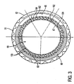
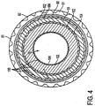
- FIGS. 3 and 4 which are cross-sectional views of FIG. 2 , show the various components that protect the scintillation element 50, the electronics 57 and other sensors. These multiple levels of protection are described in detail below.
- gamma rays 28 entering the gamma detector 20 pass through a non-metallic window 71 to reach the scintillation element 50 within the detector 20.
- Other windows 65 FIG. 3 ) have been cut into a rigid dynamic enclosure 80 which surrounds the scintillation element 50.
- a scintillation element 50 responds to gamma rays 28 that have been emitted from rocks in the soil.
- the response of element 50 is to produce a tiny pulse of light that travels to a window 52 at the window end of the scintillation element 50 or is reflected into the window 52 by a reflector 67 ( FIG. 3 ) that is wrapped around the scintillation element 50.
- the light pulse travels through a first optical coupler 51, through the window 52, and through a second optical coupler 53 into the faceplate of a light detecting element, shown here as a photo-multiplier tube 55.
- An electrical pulse is generated by the photo-multiplier tube 55 and sent to electronics element 57.
- the photo-multiplier tube 55, the electronics element 57 and an accelerometer 60 are located in an assembly called a photo-metric module 58. Since components within the photo-metric module 58 utilize electricity, it is necessary that it be enclosed in an explosion-proof housing 59 to avoid accidental ignition of gas or dust that may be in the vicinity of the detector 20. Also, the explosion-proof housing 59 serves as an effective barrier that protects the electrical elements 57 and the accelerometer 60 from the strong electromagnetic fields generated by heavy electrical equipment.
- FIGS. 3 and 4 The first view in FIG. 3 shows a support mechanism 100 that surrounds the scintillation element 50, and protects it from high levels of lower frequency vibrations.
- the support mechanism 100 will be described in greater detail below.
- the support mechanism 100 between the scintillation element 50 and the scintillation shield 63 supports the fragile scintillation element 50 and provides a high resonant frequency so that it will not resonate with lower frequency vibrations that pass through the outer housing.
- the outer housing 82 encloses another support mechanism 100, the rigid enclosure 80 and a rigid elastomeric shock absorbing sheath 81 which surrounds the enclosure 80.
- a typical size scintillation element 50 for this application is 3.6 cm (1.4 inches) in diameter by 2.5 cm (10 inches) in length, but may be as large as 5.1 cm (2 inches) in diameter.
- the resonant frequency of these outer support elements 81, 80 protect against shock and isolate the scintillation element 50 from high frequencies.
- FIG. 4 illustrates a view of a photo-metric module including a photo-multiplier tube 55 inside a first housing 58, which is within the explosion-proof housing 59.
- the support mechanism 100 is located at three radial elevations about the photo-multiplier tube 55: between the photomultiplier tube 55 and the first housing 58; between the first housing 58 and the explosion-proof housing 59; and between the explosion-proof housing 59 and the rigid enclosure 80.
- the elastomeric shock-absorbing sheath 81 fully covers the entire rigid dynamic enclosure 80. It should be noted that this sheath 81 serves other useful purposes. It provides good mechanical compliance with the armor 70. This is particularly important during installation in which dust and particles will be present. Another purpose of the sheath 81 is to prevent water or dust from entering through the window in the enclosure 80.
- the accelerometer module 60 is afforded the same critical protection from the harsh environment as the photo-multiplier tube 55.
- the exemplary optical coupling between the photo-multiplier tube 55 and the window 52 is a two-piece compound coupling.
- One piece of the coupling is a soft, self-wetting pad typically made from a material called Wacker.
- a ring Surrounding this inner coupling is a ring made from a more substantial material such as Sylgard, also pliable, optically transparent material.
- the photo-multiplier tube 55 must not be free to move more than a few thousands of a cm (an inch) in the radial direction, while at the same time, be pushed with a uniform force against the coupling elements and by a spring. To accomplish these dual requirements, the photo-multiplier tube 55 must be sufficiently free to move in the longitudinal direction while having its motion in the radial direction significantly restrained. Moreover, thermal expansion must not interfere with the two requirements discussed above.
- the support mechanism 100 comprises support rings which are placed around the photo-multiplier tube 55.
- the support mechanism 100 will be described with reference to FIGS. 5 and 6 .
- a main component of the support structure 100 is a support ring 102, an example of which is shown in FIG. 5 .
- Such a support ring 102 is commonly referred to as a tolerance ring in several industrial applications.
- One manufacturer of such rings is USA Tolerance Rings in Pennington, New Jersey.
- the tolerance, or support ring is a device that facilitates fitting of concentric cylindrical parts.
- the support ring 102 has corrugated bumps 104 which have a height 112.
- the support ring 102 also has a height 110 and a diameter 114, and may have a rim 108.
- the corrugated bumps extend, or face, toward the center of the support ring 102.
- the inward facing corrugated bumps 104 compress in proportion to torque or radial load for wider dimensional tolerance.
- the support ring 102 is not continuous, and has an opening 103. In use, the opening 103 allows the support ring 102 to flex to accommodate different diameters, to move and to absorb shock and to thermally expand.
- a support ring with a part number of ANL-R8-9-S from USA Tolerance Rings can be used.
- Such a support ring has a diameter 114 of approximately 2.858 cm (1.125 inches), a height 110 of approximately 0.795 cm (0.313 inches), and a bump height 112 of approximately (0.635 cm (0.25 inches).
- the heights 110, 112 of the support ring 102 and bumps 104, and other parameters, may be varied to accommodate design parameters.
- the support ring 102 is a frictional fastener, capable of handling direct torque transfer, torque slip, axial retention, controlled collapse and radial loading between mating cylindrical components. It is a corrugated metal strip that acts as an interface between two mechanical objects, to secure one to the other by interference fit.
- the corrugated bumps 104 deflect and allow the support ring 102 to act like an elastic shim.
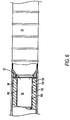
- the number of the support rings 102 is chosen depending on the configuration of the photo-multiplier tube 55. In an exemplary embodiment, between two and five support rings are used. With reference to FIG. 6 , three support rings 102 are shown supporting the photo-multiplier tube 55.
- the support rings 102 may be held in place by metal tape or a metal retainer, designated by numeral 106.
- the metal tape 106 has an adhesive material on its inward facing surface.
- the metal tape, or retainer 106 is installed about the housing 120 of the photo-multiplier tube 55.
- the metal tape or retainer 106 also functions as a spacer to laterally separate the support rings 102.
- the support rings 102 do not extend longitudinally along the photo-multiplier tube 55. Rather, the support rings 102 extend around the circumference of the photo-multiplier tube 55, and are spaced out in intervals along its length.
- FIG. 7 shows the scintillation element 50, photo-multiplier tube 55 and electrical elements 57 supported by the support mechanism 100.
- the support rings 102 are shown at different radial elevations with respect to the supported components 50, 55, 57.
- the support rings 102 at different radial elevations do not have to be concentric and can be spaced apart along the length of the protected elements 50, 55, 57.
- FIG. 8 shows a close-up view of the support mechanism 100.
- the support rings 102 are separated by the metal tape or retainer 106.
- the support rings 102 do not extend axially along the length of the photo-multiplier tube 55. Rather, the support rings 102 are spaced apart axially, and extend around the circumference of the photo-multiplier tube 55.
- the tolerance rings 102 and the photo-multiplier tube housing 120 are of the same material, or material with equivalent thermal expansion coefficient, there will be very little differential expansion due to thermal changes. In applications where the vibration and shock are the most serious environmental challenges and thermal changes are not significant, the choice of materials may not be very significant. In applications such as down-hole drilling for oil and gas, careful attention must be paid to the selection of compatible materials to avoid significant thermal expansion.
- the housing around the photo-multiplier tube 55 is rigidly connected to a crystal outer housing so that the crystal outer housing and the photo-multiplier tube 55 do not move relative to each other. Therefore, if the support rings 102 do not allow excessive motion in the radial direction of the photo-multiplier tube housing 120 relative to the first housing 58, then the photo-multiplier tube 55 would be held sufficiently well relative to the window 52 of the housing and crystal package combination.
- the support rings 102 are made from soft materials, such as elastomers, then they would tend to have a low resonant frequency and a relatively high dynamic transmissibility. This is known to have undesirable consequences. If the rings are made from a rigid material such as solid steel, then the tolerances of all the mating parts would have to be made extremely precise to prevent the elements from being loose, and they would have to be installed in a tight tolerance condition. Yet, if the support rings 102 are tight and rigid, then any errors in tolerances would render the support rings 102 difficult or impossible to install without damaging the delicate instruments. Some instruments for harsh environments are known to be designed in just this manner, and are known to be costly to manufacture. The solution is to use support rings 102 that are made from a strong material, such as stainless steel, but configured such that the support rings 102 have some elastic properties.
- the support rings 102 need to be very thin.
- unique design parameters for the support rings 102 are selected to meet particular requirements of the application for which the support rings 102 are used. Some of the particular requirements are as follows.
- the overall thickness of the support rings 102 is selected to fill gaps and tolerances between two components, and selection of appropriate tolerance rings is made using vendor catalog data.
- Friction forces exerted by the support rings 102 must be sufficient to prevent relative longitudinal motion between two components due to vibration forces, while the size of the support rings 102 must remain small enough to allow ease of assembly. Examples of nominal friction forces are 178 N (40 pounds-force) for a 2.54 cm x 10.16 cm (1 inch x 4 inch) detector, and 556 N (125 pounds-force) for a 5.08 x 25.4 cm (2 inch x 10 inch) detector.
- Support ring 102 data provided by vendors, includes: Torque; Capacity; Diametral Clearance; material thickness; and corrugation pitch. These and other parameters are used to determine the appropriate support ring characteristics.
- a support ring 102 Another consideration when selecting a support ring 102 is protection in a high vibration environment. This is achieved by a natural vibration frequency of the combination of the component and support ring. The natural vibration frequency should not adversely couple with the vibration loads of the environment. Vibration environments that must be protected against are typically in the 100 - 200 Hz range. Thus, support rings 102 would typically be designed to provide a natural vibration frequency greater than 300 Hz. Stiffness of the support ring is the key parameter used to control the natural vibration frequency. Support ring vendor catalogs typically provide data used to determine support ring stiffness.
- Still another consideration is to provide adequate structural support to components in order to prevent structural failure due to damaging acceleration loads.
- Multiple support rings 102 may be used along the length to provide support as needed to reduce mechanical stress.
- Traditional stress analysis techniques are used to determine where and how many support rings are needed.
- the support rings 102 can be selected and installed to provide resistance to movement in the longitudinal direction within acceptable limits while limiting the movement in the axial direction to a few thousands of a cm (an inch).
- the support system 100 comprising the support rings 102 protects optical coupling elements from excessive stress.
- the present inventions offer several advantages, as follows.
- the inventions provide a lower cost method of supporting instrumentation packages and sensors using off-the-shelf commercial parts.
- the inventions provide a more convenient method of delivering stiff support to an undersized component fitted into a standard sized housing (i.e., filling of the gap and tolerance).
- a detector assembly e.g., electronics and crystal elements
- use of tolerance rings allows the parts to be assembled without using sleeves to increase the smaller diameter.
- Another desirable result is that a lesser amount of radiation is blocked from entering into the scintillation element.
- the support mechanism 100 having support rings 102 supports only at two or more locations of the scintillation element. This is possible because of the relative high stiffness of the support ring 102 due to the curved shape of the bumps 104. If the support ring 102 has a rim 108, i.e., the bump 104 does not extend the full height 110 of the support ring 102, the ring will be even stiffer. This improves optical performance of the scintillation element. Since tolerance rings support only at locations of the scintillation element, this leaves a significant portion of the reflective tape along the length of the scintillation element not compressed, and uncompressed reflective tape has superior optical performance.
- the support mechanism having support rings 102 works well where the annular gap between the photo-multiplier tube and its rigid housing is not uniform. Because the support rings do not extend along the axial length of the photo-multiplier tube, variances in the gap dimension in one location will not affect the dynamics of the system in another location. Each support ring 102 acts independently of other support rings 102.
- one method is to use wraps of teflon and steel between the scintillation reflector 67 and the support rings 102.
- the scintillation element 50 is wrapped with teflon tape to about 0.076 cm (0.03 inches), uncompressed, or with approximately 0.038 cm (0.015 inches) thick sheet of skived teflon to serve as a reflector.
- a thin layer of stainless steel ideally 0.005 cm to 0.013 cm (.002 inches to 0.005 inches) thick, is then wrapped around the teflon reflector, with the joint of the stainless steel wrap positioned on the opposite side of the scintillation element 50 from the joint of the skived teflon sheet.
- the inside surface of the steel wrap can be coated white, or with a reflective material to provide additional reflection of any light that may pass through the teflon reflector.
- Support rings 102 are then placed around this assembly with tape or bonded material to hold the rings in place, similar to the way elements 106 in Figure 8 are used in the embodiment described earlier.
- Another method is to wrap the reflector 67, which is around the scintillation element 50, with two layers of stainless steel, the inside surface of the inside layer of stainless steel being coated with a reflecting material.
- the two layers of stainless steel would be separated by an elastomeric material that is molded or bonded, in the form of ridges or strips, to the surface of one of the layers (similar to the ridges of sheath 81 in Figure 3 ).
- This approach is low cost and reduces the compression forces due to the expansion of the scintillation element 50 during temperature changes so that the support rings 102 may be a stiffer configuration to make installation simpler.
- a compound optical coupler that transmits light pulses from a scintillation element 50 into the light detector device (e.g., photomultiplier tube 55).
- the invention includes a self-wetting clear optical coupling gel 202, which can be Wacker, for example, and a special elastomeric load ring 204, which can be Sylgard, for example.
- the load ring 204 can comprise another rubber-type material.
- the elastomeric load ring 204 is molded or otherwise attached to the face of the photomultiplier tube 55 and the window unit 52 to form an annular ring with an outer diameter that is preferably the same as that of photomultiplier tube 55.
- the inner diameter of the load ring 204 is sized based on the forces that it must withstand.
- a self-wetting optical material is then poured into the inner annulus of the load ring 204, forming a slightly convex surface. The convex surface allows for good contact with the self-wetting coupler material prior to engaging the elastomeric load ring 204, thus providing a good optical interface.
- the drawbacks associated with previous attempts to use a self-wetting clear material in an optical coupler are circumvented by the present invention which uses an elastomeric load ring 204.
- the elastomeric load ring 204 made from an elastomeric material can be bonded, or otherwise attached to the light detector device (e.g., photomultiplier tube 55) or to a window of a scintillation element 50 as an annular ring outside the primary light paths.
- the elastomeric load ring 204 serves as: (1) the primary load path to maintain the interface forces between the scintillation element 50 and the light detector device; and (2) as a retainer ring to prevent migration of the soft self-wetting clear material 202 from the interface.
- the result is an interface between the scintillation element 50 and light detector device that is self-healing, is pliable enough to maintain a clear bubble-free interface under extreme loads and vibration, and is more tolerant of fabrication and/or assembly tolerances.
- a gamma detector 250 having a support mechanism 300, which will be described in greater detail below.
- the gamma detector 250 has a scintillation element 50 (or “crystal") and a photo-multiplier tube 55 (or “PMT") separated by an optical coupler 252, which may be a compound optical coupler as described above.
- a photo-multiplier tube/scintillation element separation plane is represented by numeral 266.
- the gamma detector 250 has a wire insulator 254, wire clearance support 256, a hermetic feed through part 260 and an end fitting 258 to accommodate wires coming from the photo-multiplier tube 55.
- the gamma detector 250 has a photo-multiplier tube housing 264 and a scintillation element housing 268.
- the photo-multiplier tube housing 264 is a solid housing
- the scintillation element housing 268 is a split housing.
- the split housing 268 helps restrain the scintillation element crystal at the photomultiplier tube interface, and functions to lock the PMT and crystal together.
- the gamma detector 250 has a reflector 272, and a longitudinal clearance 270 between the reflector 272 and housing 268.
- the gamma detector has longitudinal support springs 262 and an outer housing assembly 276.
- the outer housing assembly may comprise multiple layers of housings, as described and illustrated above with respect to gamma detector 250.
- the support mechanism 300 is illustrated in greater detail in FIGS. 11 and 12 .
- the support mechanism 300 comprises friction rings 302 and shock rings 330.
- the shock rings 330 are elastomeric O-rings comprising viton rubber and having a durometer of 75.
- the friction rings 302 and O-rings 330 are disposed between the outer housing assembly 276 and scintillation element housing 268 or photo-multiplier tube housing 264.
- another preferred embodiment of the support mechanism 300 has friction rings 302 and O-rings 330 disposed between the outer housing assembly 276 and an outer support housing 278.
- a lubricant 280 is disposed between the outer support housing 278 and housing 264, 268.
- the friction rings 302 are described in more detail with reference to FIGS. 13-15 .
- the friction ring is made from a corrugated sheet 320.
- the friction ring comprises 17-7 PH Condition C stainless steel, heat treated to CH 900 after being formed into its final shape.
- the corrugated sheet of metal 320 has peaks 304 and flat portions 306.
- the corrugated sheet 320 has a length 308, a width 310, a height 312 and a thickness 314.
- the width 310 is between approximately 0.64 and 2.54 cm (0.25 and 1.0 inches)
- the height 312 is between approximately 0.025 and 0.254 cm (0.010 and 0.10 inches).
- the length is chosen to accommodate the circumference of the scintillation element 50 and/or photo-multiplier tube 55. As shown in FIG. 15 , the ends of the corrugated sheet 320 are brought together to form the friction ring 302, having a gap 316 between ends of the sheet 320.
- the number of the friction rings 302 is chosen depending on the configuration of the gamma detector 250. In an exemplary embodiment, between four and seven friction rings are used.
- the friction rings 302 do not extend longitudinally along the gamma detector 250. Rather, the friction rings 302 extend around the circumference of the photo-multiplier tube 55 and/or scintillation element 50, and are spaced out in intervals along its length.
- the friction rings 302 may be disposed at different radial elevations with respect to the supported components 50 and 55, as discussed and illustrated above with respect to support rings 102.
- the friction rings 302 at different radial elevations do not have to be concentric and can be spaced apart along the length of the protected elements 50, 55.
- the gamma detector's inner assembly - the scintillation element/photo-multiplier tube and reflective layer 274 - is supported by the friction rings 302 most of the time during operation.
- the friction rings 302 provide static support to the inner assembly for acceleration forces of up to 30 Gs, but not more than 50 Gs, where G is the acceleration due to gravity.
- the numerical value for the acceleration of gravity G is most accurately known as 9.8 m/s 2 , with slight variations dependent primarily upon on altitude.
- the O-rings 330 do not provide support to the inner assembly.
- the shock exerted on the gamma detector 250 exceeds the threshold of the static support of friction rings 302, the inner assembly will begin to move, or slide, relative to the surfaces of the friction rings 302.
- Such sliding friction is a very effective damping mechanism.
- the friction rings 302 cannot prevent the inner assembly from moving to the point of impacting the housings 264, 268.
- the O-rings 330 function as shock absorbers that limit movement of the inner assembly such that the inner assembly does not impact the housings 264, 268. In case the inner assembly does impact the housings 264, 268, the O-rings 330 function to ensure that the effect of the impact is not damaging.
- each friction ring 302 does not allow movement of the inner assembly at the same instant, and friction forces between the friction rings and the inner assembly are reduced once movement, or sliding, begins.
- the O-rings 330 function to distribute the friction forces and to minimize movement of one portion of the inner assembly relative to other portions of the inner assembly.
- the outside diameter (O.D.) of the installed O-rings 330 will typically be slightly smaller than the inside diameter (I.D.) of the housings 264, 268.
- I.D. inside diameter
- a small amount of mechanical interference between the O-rings 330 and the housings 264, 268 will not impair the quality of the support mechanism 300.
- such mechanical interference may complicate installation of the components of the support mechanism 300, and may result in problems caused by differential thermal expansion of the components.
- the O.D. of the installed O-rings 330 is slightly smaller than the I.D. of the housing 276.
- An exemplary difference between the O.D. of the O-rings 330 and the I.D. of the housing 276 is approximately 0.005 cm (0.002 inches).
- a suitable tolerance for an assembly for a scintillation crystal 2.54 cm (one inch) in diameter is +/- 0.010 cm (0.004 inches)
- a suitable tolerance for the I.D. of the housing 276 is +/- 0.005 cm (0.002 inches).
- Friction rings 302 could be made from a thicker material, so that the friction forces between the friction rings 302 and the inner assembly would not be overcome even during high shocks up to 1000 Gs. O-rings 330 would not be needed in such a configuration. However, such a configuration for the support mechanism 250 would not be compliant when temperature cycles as high as 175 °C, or even higher in some applications. The consequences would likely be excessive pressure on the entire assembly due to thermal expansion differential. Such differential expansion could damage the inner assembly, and, for example, cause the face of the photo-multiplier tube 55 to be pulled away from scintillation element 50.
- a desired characteristic of the support mechanism 300 is that the use of friction rings 302 produces a support mechanism with a high resonant frequency.
- a support mechanism with high resonant frequency will not resonate with lower frequency vibrations that pass through the outer housing assembly 276.
- the support mechanism 300 provides a very rigid configuration under high vibration conditions. High vibration conditions, up to approximately 30 G, are typically experienced by mining equipment, whether for coal, potash, trona, oil or gas cutting and/or drilling operations. During the high vibration conditions, the friction rings 302 are essentially not movable, or "locked up" in the support mechanism 300, producing a rigid assembly having a high resonant frequency.
- each peak 304 of the friction rings 302 is pressed against either the outer surface of the inner assembly or against the inner surface of the housings 264, 268, movement between the rings and the surfaces will be constrained by friction forces (unless high shocks overcome the friction forces).
- the peaks 304 will not slide relative to the surface of the inner assembly. Under such conditions, the portions of the flat portions 306 between the peaks 304 will be in either compression or tension, rather than bending.
- friction rings 302 are formed from a thin material - typically 0.005 to 0.015 cm (0.002 to 0.006 inches) thick - when constrained in the manner described and illustrated, compression forces pass through corrugated side walls 307 of the friction ring 302 material between the peaks 304. Such a configuration provides high stiffness.
- the friction ring peaks 304 begin to slide relative to the surfaces of the inner assembly or the housings 264, 268. At such time the friction resistance will be reduced in magnitude, since sliding friction is less than static friction. As the inner assembly moves to one side of the gamma detector 250, the peaks 304 will be forced to spread, and the friction ring material will experience significant bending forces. The resonant frequency is reduced significantly during such sliding as the overall stiffness of the assembly is greatly reduced.
- the sliding friction provides excellent damping.
- the O-rings 330 absorb the energy produced by the relative motion of the inner assembly.
- the damping from the sliding friction prevents the build-up of low resonant frequency even though a significant part of the motion restraint is due to the O-rings 330, which have a relatively low stiffness that would allow low resonance frequency to build up if not adequately damped.
- the inner assembly will once again be captured and restrained by the friction rings 302.
- a scintillation detector using the support mechanism 300 of the invention includes the O-Rings 330, friction rings 302, and housings 264, 268 with grooves to maintain proper alignment and spacing of the friction rings 302 and O-rings 330 during installation.
- the housings 264, 268 comprise a PEEK liner.
- the PEEK liner is a hard surface for the friction rings 302 to press against and spread out the load.
- the design parameters will typically be as described below. These parameters may be adjusted to satisfy application specific design parameters, or engineering and/or manufacturing preferences.
- GRMS is the root-mean-square acceleration (or rms acceleration), which is the square root of the mean square acceleration.
- Mean-square acceleration is the average of the square of the acceleration over time. Adding more friction rings 302 adds more steel around the scintillation element 50. Such would block radiation from reaching the scintillation element 50, so it would not normally be done unless needed for dynamic support under higher vibration levels. Changes should not normally be required for shock considerations since the typical practice would be to add an O-Ring 330 for each friction ring 302 added.
- Operation effectiveness of a particular design for a support mechanism 300 can be easily verified by measuring the force on the end of the scintillation element 50 required to break static friction between the friction rings 302 and the inner assembly - when the inner assembly begins to slide relative to the friction rings 302. This force should be about 30% to 50% greater the force that is expected to result from worst case scenario vibration levels. Incidental shocks are generally not considered because the O-rings 330 will serve as shock absorbers after the static friction between the friction rings 302 and the inner assembly has been exceeded. This force is simply calculated as the product of the weight of the scintillation element 50 and the G levels being designed for.
- the force required to push the scintillation element 50 should be approximately between 44 and 53 N (10 pounds and 12 pounds). This can be easily checked during prototyping by use of a simulator of the scintillation element 50, and can be checked during production as frequently as deemed useful for the assembly process being used. If a prototype is designed using the following exemplary guidelines and is found by testing to not have adequate friction resistance, additional friction rings 302 can be added. Fewer friction rings 302 can be used, but such should be done with caution if there is a chance of the detector receiving high shocks during handling or operational use.
- the design guidelines are discussed with respect to a scintillation element, they are equally applicable to a complete radiation detector assembly which also may include accelerometers, rate gyros, power supplies, microprocessors and other elements.
- the number of friction rings 302 and O-rings 330 can be reduced for the end of the detector which supports the electronics module and/or the number of friction rings 302 used on the heavier end of the detector, having the scintillation element 50, may be increased.
- good engineering judgment must be used. Fortunately, if testing of a new design indicates a problem, the number of friction rings 302 can easily be changed without a major re-start of the development process.
- friction rings 302 for support allows the design process to be greatly simplified over earlier support mechanisms, such as flexible dynamic housings and flexible sleeves.
- typical design parameters for the two major categories of scintillation element 50 sizes are discussed below.
- One typical size category is for scintillation element 50 crystals that are between 1.91 and 3.18 cm (0.75 and 1.25 inches) in diameter
- the other category is for scintillation element 50 crystals between 4.45 and 6.35 cm (1.75 and 2.5 inches) in diameter.
- the following parameters are suitable for complete gamma detectors that include scintillation elements 50, photomultiplier tubes 55, electronics and the like.
- Important parameter selections for scintillation elements between 4.45 and 6.35 cm (1.75 and 2.5 inches) in diameter include the dimensions of the friction rings 302, the number of friction rings 302, dimensions of the O-rings 330, the number of O-rings 330, radial spacing between elements, and the pitch 305, which is the distance between adjacent peaks of the sheet 320 from which friction rings 302 are made.
- the PEEK liner 264, 268 between the scintillation element 50 and the inside diameter of the outer housing 276 would typically have a wall thickness of approximately 0.178 cm (0.070 inches), and the diameter would be selected to leave a gap of approximately 0.076 cm (0.030 inches) between the PEEK liner and the shield.
- Grooves 380 should be cut into, or otherwise formed in the PEEK liner to retain the friction rings 302 ( FIG. 16 ). Making such grooves 0.089 cm (0.035 inches) deep, and making the friction ring waves 306 to have a height 312 of 0.203 cm (0.080 inches) would, in use, compress the friction rings 302 by 0.038 cm (0.015 inches). Similarly, use of standard O-rings 330 that are 0.178 cm (0.070 inches) in diameter, and making O-ring grooves 0.114 cm (0.045 inches) deep would leave the O-rings 330 with no compression, so that the O-rings 330 would not be restraining the scintillation element 50.
- the O-rings 330 would function to cushion the scintillation element 50 when shock forces exceed the friction forces. It is acceptable to choose dimensions so that there is a nominal, small gap between the O-rings 330 and the inside diameter of the shield. Ideally, there will be less than 0.025 cm (0.010 inches) of compression on the O-rings 330 at high temperatures, including tolerances, and the gap at cold temperatures, including tolerances, would be less than 0.025 cm (0.010 inches).
- O-rings 330 are viton O-rings having a hardness durometer of 75.
- the O-ring grooves 380 in the PEEK liner 264, 268 restrain movement of the O-rings in a linear direction.
- a typical arrangement of friction rings 302 and O-rings 330 would be to place friction rings 302, having a width of 1.27 cm (0.5 inches), at approximately 3.81 cm (1.5 inches) from each other along the length of a scintillation element 50.
- One O-ring 330 would be place between each pair of friction rings 302. With this arrangement, the number of O-rings 330 will be one less than the number of friction rings 302. The number of friction rings 302 and O-Rings 330 is dependent on the length of scintillation detector.
- the PEEK liner having 0.102 cm (0.040 inch) thick walls, with a longitudinal slit approximately 0,229 cm (0.090 inches) wide along the entire length of the PEEK liner is provided.
- the outer diameter of the PEEK liner is 0.086 cm (0.034 inches) smaller than the inner diameter of the outer housing assembly 276.
- Circumferential grooves 380 in the PEEK liner which is formed into a tube, are included to retain in place the friction rings 302 and O-rings 330 during and after assembly. Grooves 1.334 cm (0.525 inches) wide by 0.051 cm (0.020 inches) deep are incorporated into the PEEK liner to accommodate friction rings that are 1.27 cm (0.5 inches) wide.
- grooves 0.102 cm (0.040 inches) wide by 0.038 cm (0.015 inches) deep in the PEEK liner accommodate O-rings having a cross-section diameter of 0.081 cm (0.032 inches).
- friction rings 302 have a width of 1.27 cm (0.5 inches), a height of 0.089 cm (0.035 inches), and pitch of 0.64 cm (0.25 inches).
- circular O-rings 330 are made from Viton rubber, having a cross-sectional diameter of 0.081 cm (0.032 inches).
- the O-rings 330 have an outer diameter that is 0.061 cm (0.024 inches) greater than the outer diameter of the PEEK liner tube.
- Such a configuration provides a gap between the outer diameter of the O-Ring and the sleeve.
- the O-rings 330 do not function to restrain the inner assembly under normal low shock operations.
- An installation liner 428 (shown in FIG. 17 ), which in a preferred embodiment is made from 0.005 cm (0.002 inch) thick stainless steel wrap, is installed around the outside of the friction rings 302 and O-rings 330 to facilitate installation of the support mechanism 300 into the sleeve.
- the installation liner 428 covers the assembly so that when it is installed into the outer housing assembly 276, the friction rings 302 and O-rings 330 do not become caught on any rough surfaces and displaced.
- the PEEK liner is fabricated by machining a section of PEEK tube, or solid PEEK material, to the dimensions described above in the design considerations section.
- the fabrication of the PEEK liner includes cutting of a 0.229 cm (0.090 inch) wide longitudinal slit 382 along the PEEK liner, which is formed into a tube.
- PEEK is known to be suitable for use as a liner around a sodium iodide crystal since it has a thermal coefficient of expansion of approximately equal to that of the crystal.
- the PEEK material after being baked at 200 degrees C, will not off-gas or lose its mechanical properties as do many plastic materials.
- Manufacture of friction rings typically starts with cutting 1.27 cm (0.5 inch) wide strips from a 17.7 Ph stainless steel that is 0.005 - 0.015 cm (0.002 - 0.006 inches) thick. Such stainless steel is a condition C material. Length of such strips is optional. It is desirable, however, that the sheets 320 be long enough to fabricate several friction rings 302 from one strip.
- Each of the 1.27 cm (0.5-inch)-wide strips is run between wave shaping wheels on a Beading Machine to create the wave shapes 306 of the friction ring 302.
- An example of such a Beading Machine is Model 0581 from the Roper Whitney Company.
- the strips are cut into sheets 320 having a length 308 equal to the circumferential length of the individual friction ring 302.
- the length 308 for a sheet 320 for use with a 2.54 cm (1 inch) diameter scintillation element crystal would be 7.57 cm (2.98 inches).
- Assembly considerations for a support mechanism 300 are now discussed. Initially, all mechanical parts are cleaned and gathered to prepare for assembly. The window unit is bonded to the two part optical coupler, as discussed above, and thereafter the window unit is welded to the housing. At this stage, all moisture is baked out from all of the parts. Next, the scintillation element crystal is compensated, and the scintillation element crystal interface is polished. Compensation is a preparation procedure for the outer surface of the crystal so that it will reflect light for optimum performance.
- the scintillation element crystal is next wrapped with, in a preferred embodiment, three layers of compressed Teflon tape, and the Teflon tape is covered with reflective layer 274.
- the PEEK liner is installed over the scintillation element crystal package.
- the support mechanism 300 is further assembled by installing O-rings 330 in grooves of the PEEK liner, and friction rings 302 are installed into grooves of the PEEK liner.
- a tape such as kapton tape is used to secure the friction rings into the grooves of the PEEK liner.
- the PEEK liner 264, 268 is wrapped with a 0.002 assembly installation tool, and the assembly is installed into the outer housing 276.
- a reflector 272 is then placed onto a rear surface of the scintillation element crystal 50, and compression plates and shims 263 are added to the rear surface of the scintillation element crystal.
- longitudinal support springs 262 which in a preferred embodiment comprise wave springs, are installed the rear of scintillation crystal package with enough linear force to override the friction force of the friction rings by approximately 25%.
- the end cap is then installed and welded into place.
- the scintillation element crystal is then prepared for assembly as discussed above. Namely, the scintillation element crystal is compensated, and the scintillation element crystal interface is polished. The scintillation element crystal is next wrapped with, in a preferred embodiment, three layers of compressed Teflon tape, and the Teflon tape is covered with reflective layer 274. Next the PEEK liner is installed over the scintillation element crystal package.
- the support mechanism 300 is further assembled by installing O-rings 330 in grooves of the PEEK liner, and friction rings 302 are installed into grooves of the PEEK liner.
- a tape such as kapton tape is used to secure the friction rings into the grooves of the PEEK liner.
- the assembly process continues by inserting the scintillation element crystal package into photomultiplier tube package, with the polished end of crystal resting against the optical coupler.
- the photomultiplier tube and scintillation element crystal are then placed into an assembly fixture.
- a reflector is placed onto the rear of the scintillation element crystal, and compression plates and shims are added on the rear of scintillation crystal package.
- wave springs 262 are installed on rear of the scintillation element crystal package, with enough linear force to override the friction force of the friction rings 25%, approximately.
- the assembly is completed by wrapping the scintillation element crystal package and the photomultiplier tube package with a .002 installation tool, as discussed above.
- the housing is then installed over scintillation element crystal package and photomultiplier tube package, so that the housing is completely seated onto the hermetic feed thru 260.
- the feed thru 260 is welded to the housing, and the unit is thermal cycled prior to performing any tests.
- wires are installed onto the feed thru 260.
- appropriate detector ends 265 are installed onto the detector, and performance and environmental testing can begin.
- FIG. 16 An embodiment of the PEEK liner 264, 268 is shown in FIG. 16 .
- the PEEK liner 264, 268 has grooves 380 into which friction rings 302 and O-rings 330 are installed, as discussed above.
- the PEEK liner 264, 268 also has a longitudinal slit 382, as shown.
- the dimensions shown in FIG. 16 are in inches, and are only an example of a configuration according to a preferred embodiment of the PEEK liner 264, 268.
- FIG. 17 shows a cross-sectional view of an assembled detector having a support mechanism 300 in accordance with an embodiment of the present invention.
- FIG. 17 shows the outer housing 276 having a thickness 410, and having a clearance 412 between it and the PEEK liner 264, 268.
- the outer housing 276 has a clearance 414 between it and the O-ring 330 (not shown in FIG. 17 ).
- the outer housing 276 has an inside diameter 416 and an outside diameter 418.
- FIG. 17 also shows the PEEK liner thickness at the O-ring 330 represented by numeral 420, and at friction ring 302, represented by numeral 422.
- the scintillation element crystal has a diameter 424. Clearance between the PEEK liner and the inside diameter of the outer housing 276 is represented by numeral 426.
- the housing thickness 410 is 0.114 cm (0.045 inches), and the inside diameter 416 is 5.646 cm (2.223 inches) and the outside diameter 418 is 5.875 cm (2.313 inches) to accommodate a scintillation element crystal having a diameter 424 of 5.08 cm (2 inches).
- the PEEK liner thickness 420 (at O-ring) is 0.064 cm (0.025 inches), and the PEEK liner thickness (at friction ring) 422 is 0.089 cm (0.035 inches).
- the available clearance 412 between the friction rings 302 and the outer housing 276 is 0.165 cm (0.065 inches).
- the available clearance 414 between the O-rings 330 and the outer housing 276 is 0.191 cm (0.075 inches).
- the clearance 426 between the PEEK liner 264, 268 and the inside diameter of the outer housing 276 is 0.076 cm (0.030 inches).
- the friction ring 302 has a height of 0.203 cm (0.080 inches) at 0.50 pitch
- the O-ring 330 has a diametrical cross-section of 0.178 cm (0.070 inches), and a clearance of 0.013 cm (0.005 inches) to the internal diameter of the outer housing 276.
Landscapes
- Physics & Mathematics (AREA)
- General Physics & Mathematics (AREA)
- Electromagnetism (AREA)
- High Energy & Nuclear Physics (AREA)
- Life Sciences & Earth Sciences (AREA)
- General Life Sciences & Earth Sciences (AREA)
- Geophysics (AREA)
- Thermal Sciences (AREA)
- Fluid Mechanics (AREA)
- Health & Medical Sciences (AREA)
- Molecular Biology (AREA)
- Spectroscopy & Molecular Physics (AREA)
- Measurement Of Radiation (AREA)
- Gyroscopes (AREA)
Claims (4)
- Kit d'élément de scintillation, comprenant :un élément de scintillation (50) ;un logement d'élément de scintillation (268) comprenant un revêtement (268) ;un logement externe (276) qui contient ledit élément de scintillation (50) ; etun mécanisme de support (300) comprenant au moins une bague de frottement (302), ledit mécanisme de support (300) se trouvant entre ledit élément de scintillation (50) et ledit logement externe (276),dans lequel ledit revêtement (268) se trouve entre ladite au moins une bague de frottement (302) et ledit élément de scintillation (50),caractérisé en ce que ledit mécanisme de support (300) comprend en outre au moins un joint torique (330), eten ce que ledit revêtement (268) est un revêtement en PEEK qui comprend des rainures (380) destinées à contenir chacune desdites au moins une bague de frottement (302).
- Kit de tube de photomultiplicateur, comprenant :un tube de photomultiplicateur (55) ;un logement de tube de photomultiplicateur (264) comprenant un revêtement (264) ;un logement externe (276) qui contient ledit tube de photomultiplicateur (55) ; etun mécanisme de support (300) comprenant au moins une bague de frottement (302), ledit mécanisme de support (300) se trouvant entre ledit tube de photomultiplicateur (55) et ledit logement externe (276),dans lequel ledit revêtement (264) se trouve entre ladite au moins une bague de frottement (302) et ledit tube de photomultiplicateur (55),caractérisé en ce que ledit mécanisme de support (300) comprend en outre au moins un joint torique (330), eten ce que ledit revêtement (264) est un revêtement en PEEK comprenant des rainures (380) destinées à contenir chacune desdites au moins une bague de frottement (302).
- Ensemble de détecteur gamma (250), comprenant :un tube de photomultiplicateur (55) ;un logement de tube de photomultiplicateur (264) comprenant un revêtement (264) ;un élément de scintillation (50) ;un logement d'élément de scintillation (268) comprenant un revêtement (268) ;un logement externe (276) qui contient ledit tube de photomultiplicateur (55) et ledit élément de scintillation (50) ; etun mécanisme de support (300) comprenant au moins une bague de frottement (302),dans lequel ledit revêtement (264, 268) est disposé autour dudit tube de photomultiplicateur (55) et dudit élément de scintillation (50) ; etdans lequel ladite au moins une bague de frottement (302) est disposée autour dudit revêtement (264, 268),caractérisé en ce que ledit mécanisme de support (300) comprend en outre au moins un joint torique (330) ; eten ce que ledit revêtement (264, 268) est un revêtement en PEEK comprenant des rainures (380) destinées à contenir chacune desdites au moins une bague de frottement.
- Appareil selon les revendications 1, 2 et 3, dans lequel ladite au moins une bague de frottement (302) possède au moins deux crêtes (304) et une partie plate (306) entre lesdites au moins deux crêtes (304).
Priority Applications (1)
| Application Number | Priority Date | Filing Date | Title |
|---|---|---|---|
| PL07763156T PL1996904T3 (pl) | 2006-02-06 | 2007-02-06 | Złożony sprzęgacz optyczny i mechanizm podtrzymujący |
Applications Claiming Priority (2)
| Application Number | Priority Date | Filing Date | Title |
|---|---|---|---|
| US11/347,567 US7381957B2 (en) | 2004-08-05 | 2006-02-06 | Compound optical coupler and support mechanism |
| PCT/US2007/003254 WO2007092497A2 (fr) | 2006-02-06 | 2007-02-06 | Coupleur optique composé et mécanisme support |
Publications (3)
| Publication Number | Publication Date |
|---|---|
| EP1996904A2 EP1996904A2 (fr) | 2008-12-03 |
| EP1996904A4 EP1996904A4 (fr) | 2015-04-29 |
| EP1996904B1 true EP1996904B1 (fr) | 2019-05-29 |
Family
ID=38345775
Family Applications (1)
| Application Number | Title | Priority Date | Filing Date |
|---|---|---|---|
| EP07763156.2A Active EP1996904B1 (fr) | 2006-02-06 | 2007-02-06 | Coupleur optique composé et mécanisme support |
Country Status (6)
| Country | Link |
|---|---|
| US (2) | US7381957B2 (fr) |
| EP (1) | EP1996904B1 (fr) |
| CA (3) | CA2897090C (fr) |
| MX (1) | MX2008010076A (fr) |
| PL (1) | PL1996904T3 (fr) |
| WO (1) | WO2007092497A2 (fr) |
Families Citing this family (16)
| Publication number | Priority date | Publication date | Assignee | Title |
|---|---|---|---|---|
| US8217356B2 (en) * | 2008-08-11 | 2012-07-10 | Saint-Gobain Ceramics & Plastics, Inc. | Radiation detector including elongated elements |
| WO2010135301A2 (fr) * | 2009-05-20 | 2010-11-25 | Schlumberger Canada Limited | Scintillateurs et détecteurs souterrains |
| US8588619B2 (en) * | 2009-08-18 | 2013-11-19 | Baker Hughes Incorporated | Optical telemetry network |
| WO2013090175A1 (fr) | 2011-12-12 | 2013-06-20 | Saint-Gobain Ceramics & Plastics, Inc. | Ensemble capteur photosensible autonome |
| GB201216850D0 (en) * | 2012-09-21 | 2012-11-07 | Johnson Matthey Plc | Photomultiplier apparatus and radiation detector incorporating such apparatus |
| US9395464B2 (en) | 2013-05-15 | 2016-07-19 | Schlumberger Technology Corporation | Scintillation detector package having radioactive reflective material therein |
| US8785841B1 (en) * | 2013-05-15 | 2014-07-22 | Schlumberger Technology Corporation | Scintillation detector package having radioactive window therein |
| US9715022B2 (en) | 2013-05-15 | 2017-07-25 | Schlumberger Technology Corporation | Scintillation detector package having radioactive support apparatus |
| RU2683798C2 (ru) * | 2014-05-03 | 2019-04-02 | Толтек Груп, Ллс | Защита детектора гамма-излучения для скважинных операций |
| EP3196607B1 (fr) * | 2016-01-25 | 2020-03-04 | Berthold Technologies GmbH & Co. KG | Systeme de mesure de processus radiometrique |
| CA2980336A1 (fr) | 2017-09-25 | 2019-03-25 | Qcd Technology Inc. | Dispositif detecteur de rayon gamma en fond de trou resistant aux chocs |
| US11078763B2 (en) | 2018-08-10 | 2021-08-03 | Gr Energy Services Management, Lp | Downhole perforating tool with integrated detonation assembly and method of using same |
| US10858919B2 (en) | 2018-08-10 | 2020-12-08 | Gr Energy Services Management, Lp | Quick-locking detonation assembly of a downhole perforating tool and method of using same |
| US11994008B2 (en) | 2018-08-10 | 2024-05-28 | Gr Energy Services Management, Lp | Loaded perforating gun with plunging charge assembly and method of using same |
| US11060393B1 (en) | 2020-07-31 | 2021-07-13 | Rime Downhole Technologies, Llc | Shock isolated gamma probe |
| DE102020209901A1 (de) | 2020-08-05 | 2022-02-10 | Vega Grieshaber Kg | Radiometrisches Messgerät, Fensterelement und Verfahren zur Herstellung eines Fensterelements |
Family Cites Families (11)
| Publication number | Priority date | Publication date | Assignee | Title |
|---|---|---|---|---|
| US5070249A (en) | 1989-12-12 | 1991-12-03 | Bicron Corporation | Photomultiplier tube mounting for well logging detectors |
| US6375574B1 (en) | 1997-03-27 | 2002-04-23 | Ap Tmf Limited | Torsional vibration dampers |
| US6222192B1 (en) | 1998-07-06 | 2001-04-24 | Saint-Gobain Industrial Ceramics, Inc. | Scintillation detector without optical window |
| US6241055B1 (en) * | 1998-09-11 | 2001-06-05 | Hayes Lemmerz International, Inc. | Rotor with viscoelastic vibration reducing element and method of making the same |
| US6465788B1 (en) | 1999-12-23 | 2002-10-15 | Frederick Energy Products Llc | Ruggedized photomultiplier tube and optical coupling in armored detector |
| US6781130B2 (en) | 1999-12-23 | 2004-08-24 | Geosteering Mining Services, Llc | Geosteering of solid mineral mining machines |
| US20020056809A1 (en) | 2000-10-06 | 2002-05-16 | Frederick Larry D. | Armored rock detector |
| US6435619B1 (en) | 1999-12-23 | 2002-08-20 | Geosteering Mining Services, Llc | Method for sensing coal-rock interface |
| US20030122082A1 (en) | 2001-03-20 | 2003-07-03 | Frederick Larry D. | Flexible support mechanism |
| US20040087933A1 (en) * | 2002-09-18 | 2004-05-06 | Lee Jeong S. | Stiff guiding catheter liner material |
| US6827056B2 (en) * | 2003-01-14 | 2004-12-07 | Daimlerchrysler Corporation | Vibration friction damper |
-
2006
- 2006-02-06 US US11/347,567 patent/US7381957B2/en not_active Expired - Lifetime
-
2007
- 2007-02-06 WO PCT/US2007/003254 patent/WO2007092497A2/fr not_active Ceased
- 2007-02-06 MX MX2008010076A patent/MX2008010076A/es active IP Right Grant
- 2007-02-06 EP EP07763156.2A patent/EP1996904B1/fr active Active
- 2007-02-06 CA CA2897090A patent/CA2897090C/fr active Active
- 2007-02-06 PL PL07763156T patent/PL1996904T3/pl unknown
- 2007-02-06 CA CA2897089A patent/CA2897089C/fr active Active
- 2007-02-06 CA CA2641527A patent/CA2641527C/fr active Active
-
2008
- 2008-02-05 US US12/068,324 patent/US7485865B2/en not_active Expired - Lifetime
Non-Patent Citations (1)
| Title |
|---|
| None * |
Also Published As
| Publication number | Publication date |
|---|---|
| US20080169415A1 (en) | 2008-07-17 |
| MX2008010076A (es) | 2009-01-19 |
| CA2897089C (fr) | 2018-01-16 |
| PL1996904T3 (pl) | 2019-11-29 |
| US7381957B2 (en) | 2008-06-03 |
| US20060192126A1 (en) | 2006-08-31 |
| CA2641527C (fr) | 2018-02-20 |
| CA2897089A1 (fr) | 2007-08-16 |
| WO2007092497A3 (fr) | 2008-04-24 |
| EP1996904A2 (fr) | 2008-12-03 |
| US7485865B2 (en) | 2009-02-03 |
| CA2897090A1 (fr) | 2007-08-16 |
| CA2897090C (fr) | 2017-08-22 |
| WO2007092497A2 (fr) | 2007-08-16 |
| CA2641527A1 (fr) | 2007-08-16 |
| EP1996904A4 (fr) | 2015-04-29 |
Similar Documents
| Publication | Publication Date | Title |
|---|---|---|
| EP1996904B1 (fr) | Coupleur optique composé et mécanisme support | |
| US5962855A (en) | Maximum volume ruggedized scintillation package | |
| US6355932B1 (en) | Maximum volume ruggedized nuclear detector | |
| EP2191299B1 (fr) | Coupleur optique de compose et mecanisme de support | |
| EP0971243B1 (fr) | Détecteur à scintillations | |
| EP1399760B1 (fr) | Boitier dynamique flexible | |
| CA2789987C (fr) | Boitier d'instruments et detecteur de rayonnements integre | |
| US5742057A (en) | Unitized scintillation detector assembly with axial and radial suspension systems | |
| US8646519B2 (en) | Low-profile suspension of logging sensor and method | |
| US9018591B2 (en) | Ruggedized tool and detector device | |
| AU2002312336A1 (en) | Flexible dynamic housing | |
| US7115873B2 (en) | Compound optical coupler and support mechanism |
Legal Events
| Date | Code | Title | Description |
|---|---|---|---|
| PUAI | Public reference made under article 153(3) epc to a published international application that has entered the european phase |
Free format text: ORIGINAL CODE: 0009012 |
|
| 17P | Request for examination filed |
Effective date: 20080905 |
|
| AK | Designated contracting states |
Kind code of ref document: A2 Designated state(s): AT BE BG CH CY CZ DE DK EE ES FI FR GB GR HU IE IS IT LI LT LU LV MC NL PL PT RO SE SI SK TR |
|
| RAP1 | Party data changed (applicant data changed or rights of an application transferred) |
Owner name: TITAN SPECIALITIES, LTD. |
|
| DAX | Request for extension of the european patent (deleted) | ||
| RAP1 | Party data changed (applicant data changed or rights of an application transferred) |
Owner name: HUNTING TITAN, LTD. |
|
| RAP1 | Party data changed (applicant data changed or rights of an application transferred) |
Owner name: HUNTING TITAN, INC. |
|
| RIC1 | Information provided on ipc code assigned before grant |
Ipc: G01F 23/00 20060101AFI20141128BHEP Ipc: G01T 1/20 20060101ALI20141128BHEP Ipc: G01V 5/04 20060101ALI20141128BHEP |
|
| A4 | Supplementary search report drawn up and despatched |
Effective date: 20150331 |
|
| RIC1 | Information provided on ipc code assigned before grant |
Ipc: G01T 1/20 20060101ALI20150325BHEP Ipc: G01F 23/00 20060101AFI20150325BHEP Ipc: G01V 5/04 20060101ALI20150325BHEP |
|
| STAA | Information on the status of an ep patent application or granted ep patent |
Free format text: STATUS: EXAMINATION IS IN PROGRESS |
|
| 17Q | First examination report despatched |
Effective date: 20180511 |
|
| GRAP | Despatch of communication of intention to grant a patent |
Free format text: ORIGINAL CODE: EPIDOSNIGR1 |
|
| STAA | Information on the status of an ep patent application or granted ep patent |
Free format text: STATUS: GRANT OF PATENT IS INTENDED |
|
| INTG | Intention to grant announced |
Effective date: 20190111 |
|
| GRAS | Grant fee paid |
Free format text: ORIGINAL CODE: EPIDOSNIGR3 |
|
| GRAA | (expected) grant |
Free format text: ORIGINAL CODE: 0009210 |
|
| STAA | Information on the status of an ep patent application or granted ep patent |
Free format text: STATUS: THE PATENT HAS BEEN GRANTED |
|
| RAP1 | Party data changed (applicant data changed or rights of an application transferred) |
Owner name: HUNTING TITAN, INC. |
|
| AK | Designated contracting states |
Kind code of ref document: B1 Designated state(s): AT BE BG CH CY CZ DE DK EE ES FI FR GB GR HU IE IS IT LI LT LU LV MC NL PL PT RO SE SI SK TR |
|
| REG | Reference to a national code |
Ref country code: GB Ref legal event code: FG4D |
|
| REG | Reference to a national code |
Ref country code: CH Ref legal event code: EP |
|
| REG | Reference to a national code |
Ref country code: AT Ref legal event code: REF Ref document number: 1138543 Country of ref document: AT Kind code of ref document: T Effective date: 20190615 |
|
| REG | Reference to a national code |
Ref country code: DE Ref legal event code: R096 Ref document number: 602007058487 Country of ref document: DE |
|
| REG | Reference to a national code |
Ref country code: IE Ref legal event code: FG4D |
|
| REG | Reference to a national code |
Ref country code: SE Ref legal event code: TRGR |
|
| REG | Reference to a national code |
Ref country code: NL Ref legal event code: FP |
|
| REG | Reference to a national code |
Ref country code: LT Ref legal event code: MG4D |
|
| PG25 | Lapsed in a contracting state [announced via postgrant information from national office to epo] |
Ref country code: LT Free format text: LAPSE BECAUSE OF FAILURE TO SUBMIT A TRANSLATION OF THE DESCRIPTION OR TO PAY THE FEE WITHIN THE PRESCRIBED TIME-LIMIT Effective date: 20190529 Ref country code: PT Free format text: LAPSE BECAUSE OF FAILURE TO SUBMIT A TRANSLATION OF THE DESCRIPTION OR TO PAY THE FEE WITHIN THE PRESCRIBED TIME-LIMIT Effective date: 20190930 Ref country code: FI Free format text: LAPSE BECAUSE OF FAILURE TO SUBMIT A TRANSLATION OF THE DESCRIPTION OR TO PAY THE FEE WITHIN THE PRESCRIBED TIME-LIMIT Effective date: 20190529 Ref country code: ES Free format text: LAPSE BECAUSE OF FAILURE TO SUBMIT A TRANSLATION OF THE DESCRIPTION OR TO PAY THE FEE WITHIN THE PRESCRIBED TIME-LIMIT Effective date: 20190529 |
|
| PG25 | Lapsed in a contracting state [announced via postgrant information from national office to epo] |
Ref country code: LV Free format text: LAPSE BECAUSE OF FAILURE TO SUBMIT A TRANSLATION OF THE DESCRIPTION OR TO PAY THE FEE WITHIN THE PRESCRIBED TIME-LIMIT Effective date: 20190529 Ref country code: GR Free format text: LAPSE BECAUSE OF FAILURE TO SUBMIT A TRANSLATION OF THE DESCRIPTION OR TO PAY THE FEE WITHIN THE PRESCRIBED TIME-LIMIT Effective date: 20190830 Ref country code: BG Free format text: LAPSE BECAUSE OF FAILURE TO SUBMIT A TRANSLATION OF THE DESCRIPTION OR TO PAY THE FEE WITHIN THE PRESCRIBED TIME-LIMIT Effective date: 20190829 |
|
| REG | Reference to a national code |
Ref country code: AT Ref legal event code: MK05 Ref document number: 1138543 Country of ref document: AT Kind code of ref document: T Effective date: 20190529 |
|
| PG25 | Lapsed in a contracting state [announced via postgrant information from national office to epo] |
Ref country code: CZ Free format text: LAPSE BECAUSE OF FAILURE TO SUBMIT A TRANSLATION OF THE DESCRIPTION OR TO PAY THE FEE WITHIN THE PRESCRIBED TIME-LIMIT Effective date: 20190529 Ref country code: RO Free format text: LAPSE BECAUSE OF FAILURE TO SUBMIT A TRANSLATION OF THE DESCRIPTION OR TO PAY THE FEE WITHIN THE PRESCRIBED TIME-LIMIT Effective date: 20190529 Ref country code: SK Free format text: LAPSE BECAUSE OF FAILURE TO SUBMIT A TRANSLATION OF THE DESCRIPTION OR TO PAY THE FEE WITHIN THE PRESCRIBED TIME-LIMIT Effective date: 20190529 Ref country code: AT Free format text: LAPSE BECAUSE OF FAILURE TO SUBMIT A TRANSLATION OF THE DESCRIPTION OR TO PAY THE FEE WITHIN THE PRESCRIBED TIME-LIMIT Effective date: 20190529 Ref country code: DK Free format text: LAPSE BECAUSE OF FAILURE TO SUBMIT A TRANSLATION OF THE DESCRIPTION OR TO PAY THE FEE WITHIN THE PRESCRIBED TIME-LIMIT Effective date: 20190529 Ref country code: EE Free format text: LAPSE BECAUSE OF FAILURE TO SUBMIT A TRANSLATION OF THE DESCRIPTION OR TO PAY THE FEE WITHIN THE PRESCRIBED TIME-LIMIT Effective date: 20190529 |
|
| PG25 | Lapsed in a contracting state [announced via postgrant information from national office to epo] |
Ref country code: IT Free format text: LAPSE BECAUSE OF FAILURE TO SUBMIT A TRANSLATION OF THE DESCRIPTION OR TO PAY THE FEE WITHIN THE PRESCRIBED TIME-LIMIT Effective date: 20190529 |
|
| REG | Reference to a national code |
Ref country code: DE Ref legal event code: R097 Ref document number: 602007058487 Country of ref document: DE |
|
| PG25 | Lapsed in a contracting state [announced via postgrant information from national office to epo] |
Ref country code: TR Free format text: LAPSE BECAUSE OF FAILURE TO SUBMIT A TRANSLATION OF THE DESCRIPTION OR TO PAY THE FEE WITHIN THE PRESCRIBED TIME-LIMIT Effective date: 20190529 |
|
| PLBE | No opposition filed within time limit |
Free format text: ORIGINAL CODE: 0009261 |
|
| STAA | Information on the status of an ep patent application or granted ep patent |
Free format text: STATUS: NO OPPOSITION FILED WITHIN TIME LIMIT |
|
| PGFP | Annual fee paid to national office [announced via postgrant information from national office to epo] |
Ref country code: SE Payment date: 20200325 Year of fee payment: 14 Ref country code: PL Payment date: 20200325 Year of fee payment: 14 |
|
| 26N | No opposition filed |
Effective date: 20200303 |
|
| PG25 | Lapsed in a contracting state [announced via postgrant information from national office to epo] |
Ref country code: SI Free format text: LAPSE BECAUSE OF FAILURE TO SUBMIT A TRANSLATION OF THE DESCRIPTION OR TO PAY THE FEE WITHIN THE PRESCRIBED TIME-LIMIT Effective date: 20190529 |
|
| REG | Reference to a national code |
Ref country code: CH Ref legal event code: PL |
|
| REG | Reference to a national code |
Ref country code: BE Ref legal event code: MM Effective date: 20200229 |
|
| PG25 | Lapsed in a contracting state [announced via postgrant information from national office to epo] |
Ref country code: LU Free format text: LAPSE BECAUSE OF NON-PAYMENT OF DUE FEES Effective date: 20200206 Ref country code: MC Free format text: LAPSE BECAUSE OF FAILURE TO SUBMIT A TRANSLATION OF THE DESCRIPTION OR TO PAY THE FEE WITHIN THE PRESCRIBED TIME-LIMIT Effective date: 20190529 |
|
| PG25 | Lapsed in a contracting state [announced via postgrant information from national office to epo] |
Ref country code: LI Free format text: LAPSE BECAUSE OF NON-PAYMENT OF DUE FEES Effective date: 20200229 Ref country code: CH Free format text: LAPSE BECAUSE OF NON-PAYMENT OF DUE FEES Effective date: 20200229 |
|
| PG25 | Lapsed in a contracting state [announced via postgrant information from national office to epo] |
Ref country code: IE Free format text: LAPSE BECAUSE OF NON-PAYMENT OF DUE FEES Effective date: 20200206 |
|
| PG25 | Lapsed in a contracting state [announced via postgrant information from national office to epo] |
Ref country code: BE Free format text: LAPSE BECAUSE OF NON-PAYMENT OF DUE FEES Effective date: 20200229 |
|
| PGFP | Annual fee paid to national office [announced via postgrant information from national office to epo] |
Ref country code: NL Payment date: 20210218 Year of fee payment: 15 |
|
| REG | Reference to a national code |
Ref country code: SE Ref legal event code: EUG |
|
| PG25 | Lapsed in a contracting state [announced via postgrant information from national office to epo] |
Ref country code: SE Free format text: LAPSE BECAUSE OF NON-PAYMENT OF DUE FEES Effective date: 20210207 |
|
| PGFP | Annual fee paid to national office [announced via postgrant information from national office to epo] |
Ref country code: GB Payment date: 20220221 Year of fee payment: 16 Ref country code: DE Payment date: 20220225 Year of fee payment: 16 |
|
| PG25 | Lapsed in a contracting state [announced via postgrant information from national office to epo] |
Ref country code: CY Free format text: LAPSE BECAUSE OF FAILURE TO SUBMIT A TRANSLATION OF THE DESCRIPTION OR TO PAY THE FEE WITHIN THE PRESCRIBED TIME-LIMIT Effective date: 20190529 |
|
| PGFP | Annual fee paid to national office [announced via postgrant information from national office to epo] |
Ref country code: FR Payment date: 20220221 Year of fee payment: 16 |
|
| PG25 | Lapsed in a contracting state [announced via postgrant information from national office to epo] |
Ref country code: IS Free format text: LAPSE BECAUSE OF FAILURE TO SUBMIT A TRANSLATION OF THE DESCRIPTION OR TO PAY THE FEE WITHIN THE PRESCRIBED TIME-LIMIT Effective date: 20190929 |
|
| REG | Reference to a national code |
Ref country code: NL Ref legal event code: MM Effective date: 20220301 |
|
| PG25 | Lapsed in a contracting state [announced via postgrant information from national office to epo] |
Ref country code: NL Free format text: LAPSE BECAUSE OF NON-PAYMENT OF DUE FEES Effective date: 20220301 |
|
| REG | Reference to a national code |
Ref country code: DE Ref legal event code: R119 Ref document number: 602007058487 Country of ref document: DE |
|
| GBPC | Gb: european patent ceased through non-payment of renewal fee |
Effective date: 20230206 |
|
| PG25 | Lapsed in a contracting state [announced via postgrant information from national office to epo] |
Ref country code: GB Free format text: LAPSE BECAUSE OF NON-PAYMENT OF DUE FEES Effective date: 20230206 |
|
| PG25 | Lapsed in a contracting state [announced via postgrant information from national office to epo] |
Ref country code: GB Free format text: LAPSE BECAUSE OF NON-PAYMENT OF DUE FEES Effective date: 20230206 Ref country code: FR Free format text: LAPSE BECAUSE OF NON-PAYMENT OF DUE FEES Effective date: 20230228 Ref country code: DE Free format text: LAPSE BECAUSE OF NON-PAYMENT OF DUE FEES Effective date: 20230901 |
|
| PG25 | Lapsed in a contracting state [announced via postgrant information from national office to epo] |
Ref country code: PL Free format text: LAPSE BECAUSE OF NON-PAYMENT OF DUE FEES Effective date: 20210206 |