EP1996984B1 - Verfahren zum steuern eines rolladens unter vermeidung von zu viel belastung bei einem hindernis - Google Patents
Verfahren zum steuern eines rolladens unter vermeidung von zu viel belastung bei einem hindernis Download PDFInfo
- Publication number
- EP1996984B1 EP1996984B1 EP07713134A EP07713134A EP1996984B1 EP 1996984 B1 EP1996984 B1 EP 1996984B1 EP 07713134 A EP07713134 A EP 07713134A EP 07713134 A EP07713134 A EP 07713134A EP 1996984 B1 EP1996984 B1 EP 1996984B1
- Authority
- EP
- European Patent Office
- Prior art keywords
- moving load
- value
- obstacle
- mobile element
- controlling method
- Prior art date
- Legal status (The legal status is an assumption and is not a legal conclusion. Google has not performed a legal analysis and makes no representation as to the accuracy of the status listed.)
- Active
Links
Images


Classifications
-
- G—PHYSICS
- G05—CONTROLLING; REGULATING
- G05B—CONTROL OR REGULATING SYSTEMS IN GENERAL; FUNCTIONAL ELEMENTS OF SUCH SYSTEMS; MONITORING OR TESTING ARRANGEMENTS FOR SUCH SYSTEMS OR ELEMENTS
- G05B19/00—Program-control systems
- G05B19/02—Program-control systems electric
- G05B19/18—Numerical control [NC], i.e. automatically operating machines, in particular machine tools, e.g. in a manufacturing environment, so as to execute positioning, movement or co-ordinated operations by means of program data in numerical form
- G05B19/406—Numerical control [NC], i.e. automatically operating machines, in particular machine tools, e.g. in a manufacturing environment, so as to execute positioning, movement or co-ordinated operations by means of program data in numerical form characterised by monitoring or safety
- G05B19/4062—Monitoring servoloop, e.g. overload of servomotor, loss of feedback or reference
-
- G—PHYSICS
- G05—CONTROLLING; REGULATING
- G05B—CONTROL OR REGULATING SYSTEMS IN GENERAL; FUNCTIONAL ELEMENTS OF SUCH SYSTEMS; MONITORING OR TESTING ARRANGEMENTS FOR SUCH SYSTEMS OR ELEMENTS
- G05B2219/00—Program-control systems
- G05B2219/30—Nc systems
- G05B2219/37—Measurements
- G05B2219/37626—By measuring changing forces in different position zones
-
- G—PHYSICS
- G05—CONTROLLING; REGULATING
- G05B—CONTROL OR REGULATING SYSTEMS IN GENERAL; FUNCTIONAL ELEMENTS OF SUCH SYSTEMS; MONITORING OR TESTING ARRANGEMENTS FOR SUCH SYSTEMS OR ELEMENTS
- G05B2219/00—Program-control systems
- G05B2219/30—Nc systems
- G05B2219/45—Nc applications
- G05B2219/45015—Roller blind, shutter
Definitions
- the invention relates to a control method of a home automation equipment according to the preamble of claim 1.
- the invention also relates to an actuator for the implementation of such a method.
- This method has a drawback: the reaction times of the system are not taken into account or poorly taken into account. Indeed, the execution a stop command depends on the electronic processing time of the information from the sensor and also the mechanical response time of the system These two response times correspond to the inertia of the system. Thus, when the setpoint value is reached, the stop command is given but, in view of the reaction times, when the movable element is actually stopped, the force exerted by the movable element may be well. greater than that corresponding to the set point. This leads to choosing setpoints corresponding to efforts on obstacles well below the maximum allowable effort and to stop, therefore, the movable element well before the maximum allowable effort is reached. In the case of home automation equipment, this disadvantage is particularly sensitive that the inertia of the moving devices are far from negligible.
- DE 44 42 171 a device for making a measurement of the evolution of the actuating force applied by an actuator to a movable element as a function of time. This measurement makes it possible to deduce the force applied by the mobile element on an obstacle and to control its stopping.
- the object of the invention is to provide a control method of an actuator of a home automation equipment that obviates the disadvantages mentioned and improves the control methods known from the prior art.
- the invention makes it possible to ensure very good control of the force applied to an obstacle and to maintain a maneuvering force always lower than a predetermined value.
- control method according to the invention is characterized by the characterizing part of claim 1.
- the actuator according to the invention is provided with a motor. It is characterized in that it comprises hardware and software means for implementing the previously defined control method.
- the attached drawing shows, by way of example, an embodiment of an actuator according to the invention and two embodiments of a control method according to the invention.
- the figure 1 is a diagram of an installation comprising an actuator according to the invention.
- the Figures 2 to 5 are graphs illustrating the evolutions of the mechanical actions exerted by an actuator in different configurations.
- FIGS. 6 and 7 are graphs illustrating the evolutions of the mechanical actions exerted by an actuator from the moment when the movable element comes into contact with an obstacle in the cases where the rigidity of the obstacle is fixed and in the case where it evolves as a function of the deformation of it.
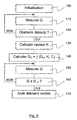
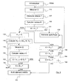
- the figures 8 and 9 are flowcharts of two embodiments of the control method according to the invention.
- the installation represented at figure 1 comprises ACT actuator capable of driving a movable element 2 closing, occultation or sunscreen equipping a building.
- This movable element can be moved in two opposite directions.
- the movable element may for example be a roller shutter comprising an apron consisting of blades, rollable on a winding tube 1 and having a lower end 3 movable between an upper extreme position 5 and a lower extreme position 4.
- the actuator is kinematically connected to the winding tube and powered by a power source ALIM. It mainly comprises a MOT engine, a ULT logic processing unit and means SW for controlling the motor power supply, these means being controlled by an output of the logic processing unit.
- the power supply control means comprise for example one or more controlled switches such as relays or semiconductor devices.
- the logic processing unit comprises for example a microcontroller and is provided with a MEM memory.
- the actuator further comprises a PS position sensor of the movable member and a TS sensor for measuring the forces applied to the winding tube.
- the position sensor of the movable member may be installed at the motor shaft and determine the position of the movable member by calculating that of the motor shaft.
- the force measuring sensor can be installed at the power supply conductors of the motor and measure the power that it consumes. Alternatively, the force measurement sensor could measure the forces at the motor shaft.
- the engine torque applied by the actuator changes differently depending on the direction of maneuver.
- the motor when raising the flap, the motor must provide a significant torque to lift the load constituted by the flap.
- the engine torque generated is directly applied to the shutter deck.
- the engine exerts a resistant torque which varies depending on the deployment of the screen.
- the motor acts as a brake to prevent the flap from coming down too quickly.
- the figure 2 illustrates the variations of the motor torque as a function of time.
- the couple increases strongly first. This increase corresponds to the stripping of the apron blades 4.
- the actuator must gradually produce sufficient torque to lift the entire weight of the deck. Then, the apron 2 wraps around the tube 1 which causes a gradual decrease in torque. Finally, the apron 2 will abut in extreme position 5. The torque then increases abruptly until the actuator is stopped.
- the engine torque has a characteristic similar to that described below with reference to the figure 3 . If the deck encounters an obstacle, the engine torque increases rapidly in a substantially linear variation whose slope is proportional to the rigidity K m1 . Subsequently, stiffness or stiffness K, the derivative of a magnitude representative of the maneuvering force of the shutter with respect to time, will be called stiffness. Derivative means the variation of this quantity with respect to a corresponding time variation, without, however, including a derivative in the strict sense of the term.
- This rigidity or stiffness associated with an obstacle corresponds to the actual stiffness of the obstacle, but also that of the entire kinematic chain between the actuator and the flap, including the apron blades which have a different stiffness extension and in compression.
- the representative magnitude is the driving torque.
- the obstacle is detected at a torque GB, this torque increasing along a slope K M1 until the actuator is stopped.
- K B5 is noted the stiffness associated with this high stop.
- the figure 4 illustrates the variations of the motor torque as a function of time.
- the starting torque is close to zero.
- the actuator opposes the friction and inertia of the installation and begins to deploy the shutter.
- the deck exerts a torque driving the engine.
- the actuator then brakes the apron. Indeed, as the deck unfolds, the suspended mass of the flap increases.
- the motor then operates as a brake.
- the deck 2 reaches the lower extreme position 4
- the blades are stacked. Once all the blades are stacked, the deck load is zero.
- the actuator no longer brakes the flap.
- the torque applied by the actuator becomes a driving torque which increases until the supply of the actuator is cut off.
- the engine torque has a characteristic close to that described below with reference to the figure 5 .
- the apron blades stack up and the resisting torque of the actuator quickly becomes motor.
- the evolution of it is first independent of the rigidity K D1 of the obstacle (stacking of the blades) and then becomes proportional to this rigidity.
- the evolution of the torque is determined by the rigidity K B4 of the lower stop.
- the obstacle encountered has a stiffness K 1 .
- the obstacle is firstly detected by a significant variation of a magnitude representative of the maneuvering force. This magnitude can be the motor torque as seen previously. This quantity is measured at regular intervals by the measurement sensor applied forces. From a break in the slope value of the measured quantity, corresponding to the value Go, the arrival of the flap in contact with the obstacle is detected. We continue to measure the evolution of the magnitude over time. We then deduce a stiffness K 1 which is the image of the rigidity of the system consisting of the kinematic drive chain of the roller shutter and the obstacle encountered. The user or the installer has previously defined a limit value Gu of the measured quantity corresponding to the maximum allowable force on the rolling shutter.
- the reference value G C1 takes into account the electronic response time T E1 and the mechanical response time of the installation T M1 , being related to the inertia of the installation.
- the mechanical response time essentially corresponds to the inertia of the motor.
- This time T M1 is more important than the electronic response time T E1 .
- We write Ti the sum of these two response times. This value is variable depending on the position of the flap and the rigidity of the obstacle.
- the time Ti can be set by the user, the installer, the manufacturer or any other person, be defined during a learning phase. This may be the case, for example, during the initialization of the actuator. To do this, the actuator executes a descent order of the shutter. At the moment when the stop is detected, the time taken by the screen to actually stop is measured. The reaction time Ti can then be estimated from this measured time. This value can also be extrapolated to the other response times Ti relative to different obstacle stiffnesses.
- the formula for calculating the set value G C1 is thus based on an extrapolation over time of the maneuvering force.
- the extrapolation is based on a polynomial law and, more exactly, on an affine law in which the derivative of the maneuvering force with respect to time is used as parameter, this parameter being multiplied by the temporal variable. .
- the rigidity of the obstacle varies with its deformation.
- the stiffness of the obstacle is calculated several times after the obstacle has been detected and the setpoint is modified following each stiffness calculation so that it corresponds to the last calculated stiffness.
- the calculated stiffness is K 2
- the calculated reference value is then G C2 .
- the stiffness of the obstacle increases to reach K 1 .
- the new calculated target value is then G C1 .
- a limit value Gu of the measured quantity corresponding to the maximum allowable force on the shutter is set. It can be set by the user, the installer, the manufacturer or any other person. It can be determined according to the position of the screen. It may, for example, wish that the maximum allowable force is greater at the beginning of the descent end of the race, when the deck reaches the extreme lower position. On the other hand, this value can be modified in time with a specific adjustment.
- the TS sensor measures the magnitude representative of the maneuvering force continuously, throughout the movement of the flap.
- the measurement frequency is defined according to the desired accuracy. In fact, the more the measurements are spaced apart, the less control of the force applied to the obstacle by the shutter during its shutdown is accurate.
- a step 120 it is analyzed whether the screen has encountered a stop. To do this, the last measured quantity is compared with the previous measurements. If the evolution is marked by a significant slope break, it means that an obstacle is encountered: then we go to a step 130. Otherwise, we loop on step 110.
- a stiffness K is calculated by analyzing the evolution of the measured quantity. For a time interval Dt, this stiffness K corresponds to the difference between the values of the quantity measured at the ends of the time interval divided by the amplitude of the time interval Dt.
- a set value Gc of the quantity measured is calculated from the stiffness K, the limit value Gu and the inertia of the installation Ti. This setpoint triggers, when the measured quantity reaches it, an order to stop the motor supply. It is determined so that, once the stop command has been executed, the shutter actually stops before the limit value Gu is reached and therefore the allowable limit force on the flap is reached.
- the calculation of this set value Gc is similar to that detailed above.
- a step 150 the value G of the measured quantity is measured again, as in step 110.
- step 160 the value G of the quantity measured in step 150 is compared with the set value Gc. If the value G is lower than the setpoint value, step 150 is looped. Otherwise, step 170 is proceeded to.
- step 170 the power supply to the motor is cut off. This has the effect of stopping the flap so that the maneuvering force applied to the obstacle is less than or equal to the maximum allowable force.
- a second embodiment, enriched with new functionalities, is described in the flowchart of the figure 9 .
- Steps 110, 120, 130, 140, 150, 160 and 170 are identical to those described above.
- the initialization step 100bis comprises two operations additional to the operation of setting the limit value Gu.
- the first is definition of a threshold value Ks. It corresponds to a significant obstacle stiffness beyond which it is desired to execute a specific scenario. It may be different depending on the position of the shutter.
- the second operation is the definition of a second threshold value Ko. It corresponds to a stiffness value below which, it is considered that an obstacle is not binding for the installation.
- the stiffness K calculated is compared with the threshold stiffness Ks previously defined. If the stiffness K is greater than the stiffness threshold Ks, then we go to a step 132. Otherwise, we go to a step 133.
- a specific scenario is executed in response to exceeding the threshold stiffness Ks.
- This scenario can be a safety scenario in which the engine power is immediately cut off and in which a slight movement is controlled, if necessary. reverse motor.
- step 133 the instantaneous value K 1 of the calculated stiffness K is stored in memory.
- steps 140 and 150 then comes a step 151 where the stiffness K is calculated again, as in step 130.
- a step 152 the new value of the stiffness is compared with the stiffness K, stored in step 133. If this value is stable, that is to say, within an interval corresponding to K, plus or minus 15%. then go to step 160. If not, go to step 153.
- step 153 the value G of the quantity of the quantity measured in step 150 is compared with the set value Gc. If the value G is greater than or equal to the set value, go to step 170 otherwise, proceed to a step 154.
- step 154 the new value of stiffness K is compared with the stiffness threshold Ks defined previously. If the stiffness value K exceeds the threshold, then the specific scenario of step 132 is executed. Alternatively, we go to a step 155.
- step 155 the new stiffness value K is compared with the other previously defined threshold value Ko.
- the goal is to check if the obstacle is still present. For example, it happens that the obstacle detected results from the friction of the apron blades in the wings. After the passage of the hard point, there is more stiffness and therefore more obstacle detected. It is then necessary to restart the monitoring. Thus, if the stiffness value is less than or equal to the value Ko, we go to step 110. If the value of the stiffness K is greater than the value of the stiffness Ko then, the obstacle has a variable stiffness for which it is necessary to recalculate the value of setpoint: one thus passes to the step 133.
- the control method according to the invention can also provide a relaxation step.
- a relaxation step may in particular be implemented when a force greater than the maximum allowable force is detected after the effective shutdown of the shutter. This step includes a slight reverse movement of the motor.
Landscapes
- Engineering & Computer Science (AREA)
- Human Computer Interaction (AREA)
- Manufacturing & Machinery (AREA)
- Physics & Mathematics (AREA)
- General Physics & Mathematics (AREA)
- Automation & Control Theory (AREA)
- Operating, Guiding And Securing Of Roll- Type Closing Members (AREA)
- Power-Operated Mechanisms For Wings (AREA)
- Housing For Livestock And Birds (AREA)
Claims (9)
- Verfahren zur Steuerung einer domotischen Ausrüstung mit einem elektrischen Betätigungsgerät (ACT), mit einem beweglichen Schliess-, Verdunkelungs- oder Sonnenschutzelement, das in einem Gebäude installiert ist und von dem Betätigungsgerät betätigt wird, sowie mit einem Mittel (TS) zum Messen der auf das bewegliche Element ausgeübten Betätigungskraft, wobei das Verfahren einen Schritt umfasst, bei dem ein automatischer Stoppbefehl ausgeführt wird, sobald ein Sollwert (Gc) der Betätigungskraft erreicht ist, dadurch gekennzeichnet, dass der Sollwert der Betätigungskraft während der Bewegung des beweglichen Elements berechnet wird, indem der zeitliche Verlauf der Betätigungskraft extrapoliert wird, um zu vermeiden, dass ein vorbestimmter Schwellwert (Gu) der Betätigungskraft während des automatschen Stopps überschritten wird.
- Verfahren nach Anspruch 1, dadurch gekennzeichnet, dass die Extrapolation des zeitlichen Verlaufs der Betätigungskraft gemäss einem polynomischen Gesetz erfolgt.
- Verfahren nach Anspruch 2, dadurch gekennzeichnet, dass die Extrapolation des zeitlichen Verlaufs der Betätigungskraft gemäss einem affinen Gesetz erfolgt.
- Verfahren nach einem der vorangehenden Ansprüche, dadurch gekennzeichnet, dass die Extrapolation des zeitlichen Verlaufs der Betätigungskraft gemäss einem mathematischen Gesetz erfolgt, das als Parameter die Ableitung der Betätigungskraft in bezug auf die Zeit verwendet.
- Verfahren nach einem der vorangehenden Ansprüche, dadurch gekennzeichnet, dass die Berechnung des Sollwerts der Betätigungskraft in regelmässigen Zeitintervallen erfolgt.
- Verfahren nach einem der vorangehenden Ansprüche, dadurch gekennzeichnet, dass der vorbestimmte Schwellenwert der Betätigungskraft von der Position des beweglichen Elements abhängt.
- Verfahren nach einem der vorangehenden Ansprüche, dadurch gekennzeichnet, dass der Sollwert der Betätigungskraft vom vorbestimmten Schwellenwert und den elektronischen und mechanischen Ansprechzeiten der domotischen Ausrüstung auf den automatischen Stopp abgeleitet wird.
- Verfahren nach einem der vorangehenden Ansprüche, dadurch gekennzeichnet, dass das Verfahren einen zusätzlichen Schritt der Relaxation des beweglichen Elements umfasst, der darin besteht, dass dem beweglichen Element ein Befehl gegeben wird, eine umgekehrte Bewegung auszuführen, bis die Betätigungskraft kleiner als der vorbestimmte Schwellenwert wird.
- Betätigungsgerät (ACT), das mit einem Motor (MOT) ausgerüstet ist, dadurch gekennzeichnet, dass es zur Durchführung des Steuerungsverfahrens nach einem der Ansprüche 1 bis 8 Hardware (ULT, MEM, TS, PS, SW) und Software aufweist.
Applications Claiming Priority (2)
| Application Number | Priority Date | Filing Date | Title |
|---|---|---|---|
| FR0602525A FR2898994B1 (fr) | 2006-03-23 | 2006-03-23 | Procede de commande d'un volet roulant evitant l'application d'un effort trop important sur un obstacle |
| PCT/IB2007/000709 WO2007107864A1 (fr) | 2006-03-23 | 2007-03-20 | Procede de commande d'un volet roulant evitant l'application d'un effort trop important sur un obstacle |
Publications (2)
| Publication Number | Publication Date |
|---|---|
| EP1996984A1 EP1996984A1 (de) | 2008-12-03 |
| EP1996984B1 true EP1996984B1 (de) | 2010-03-10 |
Family
ID=37420837
Family Applications (1)
| Application Number | Title | Priority Date | Filing Date |
|---|---|---|---|
| EP07713134A Active EP1996984B1 (de) | 2006-03-23 | 2007-03-20 | Verfahren zum steuern eines rolladens unter vermeidung von zu viel belastung bei einem hindernis |
Country Status (5)
| Country | Link |
|---|---|
| EP (1) | EP1996984B1 (de) |
| AT (1) | ATE460693T1 (de) |
| DE (1) | DE602007005232D1 (de) |
| FR (1) | FR2898994B1 (de) |
| WO (1) | WO2007107864A1 (de) |
Families Citing this family (2)
| Publication number | Priority date | Publication date | Assignee | Title |
|---|---|---|---|---|
| FR2922385A1 (fr) * | 2007-10-16 | 2009-04-17 | Somfy Sas | Procede d'analyse du fonctionnement d'un actionneur electromecanique pour la manoeuvre motorisee d'un ecran et actionneur pour sa mise en oeuvre. |
| FR2978791B1 (fr) * | 2011-08-05 | 2013-09-20 | Somfy Sas | Procede de commande d'un ecran et actionneur adapte pour un tel procede |
Family Cites Families (5)
| Publication number | Priority date | Publication date | Assignee | Title |
|---|---|---|---|---|
| DE4442171A1 (de) * | 1994-11-26 | 1996-06-13 | Telefunken Microelectron | Verfahren zur Überwachung des Öffnungs- und Schließvorgangs bei einem System mit mindestens einem elektromotorisch bewegten Teil |
| DE19628238C2 (de) * | 1996-07-12 | 1999-01-07 | Berner Kurt | Verfahren zum Steuern eines elektrischen Torantriebes |
| DE19700828C5 (de) * | 1997-01-13 | 2013-06-06 | Geze Gmbh | Verfahren zum Betrieb einer automatischen Türanlage |
| NZ511124A (en) * | 1999-05-21 | 2003-08-29 | Automatic Tech Au Pty Ltd | Control system and method for an automatic door or gate |
| DE10310480B4 (de) * | 2003-03-11 | 2006-10-12 | Sommer Antriebs- Und Funktechnik Gmbh | Verfahren und Vorrichtung zum Steuern eines Torantriebes |
-
2006
- 2006-03-23 FR FR0602525A patent/FR2898994B1/fr not_active Expired - Fee Related
-
2007
- 2007-03-20 AT AT07713134T patent/ATE460693T1/de not_active IP Right Cessation
- 2007-03-20 WO PCT/IB2007/000709 patent/WO2007107864A1/fr not_active Ceased
- 2007-03-20 EP EP07713134A patent/EP1996984B1/de active Active
- 2007-03-20 DE DE602007005232T patent/DE602007005232D1/de active Active
Also Published As
| Publication number | Publication date |
|---|---|
| FR2898994A1 (fr) | 2007-09-28 |
| ATE460693T1 (de) | 2010-03-15 |
| DE602007005232D1 (de) | 2010-04-22 |
| EP1996984A1 (de) | 2008-12-03 |
| FR2898994B1 (fr) | 2008-06-06 |
| WO2007107864A1 (fr) | 2007-09-27 |
Similar Documents
| Publication | Publication Date | Title |
|---|---|---|
| EP2075401B1 (de) | Method of adjusting a motorised solar protection installation not comprising an end-stop. | |
| EP1510649B1 (de) | Verfahren zur Initialisierung eines Rollladens | |
| EP0784146B1 (de) | Motorbetriebene Schliess- oder Sonnenschutzeinrichtung | |
| EP1508844A1 (de) | Verfahren zur Initialisierung eines motorisierten Rolladens | |
| EP3172394A1 (de) | Verfahren zur betriebssteuerung einer motorisch angetriebenen vorrichtung zum antrieb einer automatisierten schliess- oder sonnenschutzvorrichtung und zugehörige vorrichtung | |
| EP2442197A1 (de) | Betriebsverfahren eines Stellgliedes eines beweglichen, aufrollbaren Elementes eines Haushaltvorrichtung und Stellglied, das nach diesem Verfahren funktioniert | |
| EP2201674B1 (de) | Verfahren zur analyse des betriebs eines elektromechanischen aktors für die angetriebene steuerung eines bildschirms und aktor zur ausführung | |
| EP1497702B1 (de) | Verfahren zur ermittlung einer durchbrechenden lage eines roll-ladens | |
| WO2016177736A1 (fr) | Procédés de configuration et de commande en fonctionnement d'un dispositif d'entraînement motorisé d'une installation domotique, dispositif d'entraînement motorisé et installation associés | |
| WO2007107864A1 (fr) | Procede de commande d'un volet roulant evitant l'application d'un effort trop important sur un obstacle | |
| CH701707A2 (fr) | Procédé de fonctionnement d'un système de commande d'un moteur électrique d'un actionneur de store. | |
| EP2808479B1 (de) | Verfahren und Vorrichtung zur Betätigung eines mobilen Verschluss-, Verdunkelungs-, Sonnenschutz- oder Leinwandelements | |
| EP1820258A1 (de) | Verfahren zur speisung eines betriebsmotors eines rolladen und einrichtung für einen angetriebenen rolladen | |
| EP2015156B1 (de) | Verfahren zum Betrieb einer Heiminstallation und Heiminstallation zur Durchführung dieses Verfahrens | |
| EP2652234A1 (de) | Verfahren zur betätigung eines stellgliedes zum betrieb eines rollladens | |
| EP1530284B1 (de) | Verfahren und Vorrichtung zur Drehzahlregelung eines Motors für einen Rollladen | |
| EP2725182B1 (de) | Funktionsverfahren eines Betätigungsstellglieds eines beweglichen Elements einer Haustechnikanlage, und Stellglied, das nach diesem Verfahren funktioniert | |
| EP1748528B1 (de) | Verfahren zur Steuerung eines Asynchronmotors | |
| EP2450761B1 (de) | Gerät und Verfahren zum Ansteuern einer Schließvorrichtung umfassend einen Schrittmotor. | |
| FR2900959A1 (fr) | Dispositif et procede de commande d'un store ou d'un volet roulant | |
| EP2051369A2 (de) | Verfahren zur Bestimmung einer inneren Größe eines Bedienungsschalters eines beweglichen Haushaltselements | |
| EP3470615A1 (de) | Verfahren zur regulierung einer mit einem schloss ausgestatteten rollladenanlage und rollladenanlage | |
| FR2937810A1 (fr) | Procede de commande du deplacement d'une paroi mobile motorisee | |
| EP2005270A2 (de) | Verfahren zum initialisieren eines motorgetriebenen rolladens |
Legal Events
| Date | Code | Title | Description |
|---|---|---|---|
| PUAI | Public reference made under article 153(3) epc to a published international application that has entered the european phase |
Free format text: ORIGINAL CODE: 0009012 |
|
| 17P | Request for examination filed |
Effective date: 20080922 |
|
| AK | Designated contracting states |
Kind code of ref document: A1 Designated state(s): AT BE BG CH CY CZ DE DK EE ES FI FR GB GR HU IE IS IT LI LT LU LV MC MT NL PL PT RO SE SI SK TR |
|
| GRAP | Despatch of communication of intention to grant a patent |
Free format text: ORIGINAL CODE: EPIDOSNIGR1 |
|
| GRAS | Grant fee paid |
Free format text: ORIGINAL CODE: EPIDOSNIGR3 |
|
| GRAA | (expected) grant |
Free format text: ORIGINAL CODE: 0009210 |
|
| AK | Designated contracting states |
Kind code of ref document: B1 Designated state(s): AT BE BG CH CY CZ DE DK EE ES FI FR GB GR HU IE IS IT LI LT LU LV MC MT NL PL PT RO SE SI SK TR |
|
| REG | Reference to a national code |
Ref country code: GB Ref legal event code: FG4D Free format text: NOT ENGLISH |
|
| REG | Reference to a national code |
Ref country code: CH Ref legal event code: EP |
|
| REG | Reference to a national code |
Ref country code: IE Ref legal event code: FG4D |
|
| REF | Corresponds to: |
Ref document number: 602007005232 Country of ref document: DE Date of ref document: 20100422 Kind code of ref document: P |
|
| REG | Reference to a national code |
Ref country code: NL Ref legal event code: VDEP Effective date: 20100310 |
|
| PG25 | Lapsed in a contracting state [announced via postgrant information from national office to epo] |
Ref country code: LT Free format text: LAPSE BECAUSE OF FAILURE TO SUBMIT A TRANSLATION OF THE DESCRIPTION OR TO PAY THE FEE WITHIN THE PRESCRIBED TIME-LIMIT Effective date: 20100310 |
|
| LTIE | Lt: invalidation of european patent or patent extension |
Effective date: 20100310 |
|
| PG25 | Lapsed in a contracting state [announced via postgrant information from national office to epo] |
Ref country code: LV Free format text: LAPSE BECAUSE OF FAILURE TO SUBMIT A TRANSLATION OF THE DESCRIPTION OR TO PAY THE FEE WITHIN THE PRESCRIBED TIME-LIMIT Effective date: 20100310 Ref country code: PL Free format text: LAPSE BECAUSE OF FAILURE TO SUBMIT A TRANSLATION OF THE DESCRIPTION OR TO PAY THE FEE WITHIN THE PRESCRIBED TIME-LIMIT Effective date: 20100310 Ref country code: SI Free format text: LAPSE BECAUSE OF FAILURE TO SUBMIT A TRANSLATION OF THE DESCRIPTION OR TO PAY THE FEE WITHIN THE PRESCRIBED TIME-LIMIT Effective date: 20100310 Ref country code: AT Free format text: LAPSE BECAUSE OF FAILURE TO SUBMIT A TRANSLATION OF THE DESCRIPTION OR TO PAY THE FEE WITHIN THE PRESCRIBED TIME-LIMIT Effective date: 20100310 Ref country code: FI Free format text: LAPSE BECAUSE OF FAILURE TO SUBMIT A TRANSLATION OF THE DESCRIPTION OR TO PAY THE FEE WITHIN THE PRESCRIBED TIME-LIMIT Effective date: 20100310 |
|
| REG | Reference to a national code |
Ref country code: IE Ref legal event code: FD4D |
|
| PG25 | Lapsed in a contracting state [announced via postgrant information from national office to epo] |
Ref country code: GR Free format text: LAPSE BECAUSE OF FAILURE TO SUBMIT A TRANSLATION OF THE DESCRIPTION OR TO PAY THE FEE WITHIN THE PRESCRIBED TIME-LIMIT Effective date: 20100611 Ref country code: EE Free format text: LAPSE BECAUSE OF FAILURE TO SUBMIT A TRANSLATION OF THE DESCRIPTION OR TO PAY THE FEE WITHIN THE PRESCRIBED TIME-LIMIT Effective date: 20100310 Ref country code: CY Free format text: LAPSE BECAUSE OF FAILURE TO SUBMIT A TRANSLATION OF THE DESCRIPTION OR TO PAY THE FEE WITHIN THE PRESCRIBED TIME-LIMIT Effective date: 20100310 Ref country code: RO Free format text: LAPSE BECAUSE OF FAILURE TO SUBMIT A TRANSLATION OF THE DESCRIPTION OR TO PAY THE FEE WITHIN THE PRESCRIBED TIME-LIMIT Effective date: 20100310 Ref country code: SE Free format text: LAPSE BECAUSE OF FAILURE TO SUBMIT A TRANSLATION OF THE DESCRIPTION OR TO PAY THE FEE WITHIN THE PRESCRIBED TIME-LIMIT Effective date: 20100310 Ref country code: MC Free format text: LAPSE BECAUSE OF NON-PAYMENT OF DUE FEES Effective date: 20100331 Ref country code: NL Free format text: LAPSE BECAUSE OF FAILURE TO SUBMIT A TRANSLATION OF THE DESCRIPTION OR TO PAY THE FEE WITHIN THE PRESCRIBED TIME-LIMIT Effective date: 20100310 Ref country code: ES Free format text: LAPSE BECAUSE OF FAILURE TO SUBMIT A TRANSLATION OF THE DESCRIPTION OR TO PAY THE FEE WITHIN THE PRESCRIBED TIME-LIMIT Effective date: 20100621 |
|
| PG25 | Lapsed in a contracting state [announced via postgrant information from national office to epo] |
Ref country code: SK Free format text: LAPSE BECAUSE OF FAILURE TO SUBMIT A TRANSLATION OF THE DESCRIPTION OR TO PAY THE FEE WITHIN THE PRESCRIBED TIME-LIMIT Effective date: 20100310 Ref country code: BG Free format text: LAPSE BECAUSE OF FAILURE TO SUBMIT A TRANSLATION OF THE DESCRIPTION OR TO PAY THE FEE WITHIN THE PRESCRIBED TIME-LIMIT Effective date: 20100610 Ref country code: CZ Free format text: LAPSE BECAUSE OF FAILURE TO SUBMIT A TRANSLATION OF THE DESCRIPTION OR TO PAY THE FEE WITHIN THE PRESCRIBED TIME-LIMIT Effective date: 20100310 Ref country code: IS Free format text: LAPSE BECAUSE OF FAILURE TO SUBMIT A TRANSLATION OF THE DESCRIPTION OR TO PAY THE FEE WITHIN THE PRESCRIBED TIME-LIMIT Effective date: 20100710 |
|
| PLBE | No opposition filed within time limit |
Free format text: ORIGINAL CODE: 0009261 |
|
| STAA | Information on the status of an ep patent application or granted ep patent |
Free format text: STATUS: NO OPPOSITION FILED WITHIN TIME LIMIT |
|
| PG25 | Lapsed in a contracting state [announced via postgrant information from national office to epo] |
Ref country code: PT Free format text: LAPSE BECAUSE OF FAILURE TO SUBMIT A TRANSLATION OF THE DESCRIPTION OR TO PAY THE FEE WITHIN THE PRESCRIBED TIME-LIMIT Effective date: 20100712 Ref country code: IE Free format text: LAPSE BECAUSE OF FAILURE TO SUBMIT A TRANSLATION OF THE DESCRIPTION OR TO PAY THE FEE WITHIN THE PRESCRIBED TIME-LIMIT Effective date: 20100310 Ref country code: DK Free format text: LAPSE BECAUSE OF FAILURE TO SUBMIT A TRANSLATION OF THE DESCRIPTION OR TO PAY THE FEE WITHIN THE PRESCRIBED TIME-LIMIT Effective date: 20100310 |
|
| 26N | No opposition filed |
Effective date: 20101213 |
|
| PG25 | Lapsed in a contracting state [announced via postgrant information from national office to epo] |
Ref country code: IT Free format text: LAPSE BECAUSE OF FAILURE TO SUBMIT A TRANSLATION OF THE DESCRIPTION OR TO PAY THE FEE WITHIN THE PRESCRIBED TIME-LIMIT Effective date: 20100310 |
|
| PG25 | Lapsed in a contracting state [announced via postgrant information from national office to epo] |
Ref country code: MT Free format text: LAPSE BECAUSE OF FAILURE TO SUBMIT A TRANSLATION OF THE DESCRIPTION OR TO PAY THE FEE WITHIN THE PRESCRIBED TIME-LIMIT Effective date: 20100310 |
|
| REG | Reference to a national code |
Ref country code: CH Ref legal event code: PL |
|
| GBPC | Gb: european patent ceased through non-payment of renewal fee |
Effective date: 20110320 |
|
| PG25 | Lapsed in a contracting state [announced via postgrant information from national office to epo] |
Ref country code: LI Free format text: LAPSE BECAUSE OF NON-PAYMENT OF DUE FEES Effective date: 20110331 Ref country code: CH Free format text: LAPSE BECAUSE OF NON-PAYMENT OF DUE FEES Effective date: 20110331 |
|
| PG25 | Lapsed in a contracting state [announced via postgrant information from national office to epo] |
Ref country code: GB Free format text: LAPSE BECAUSE OF NON-PAYMENT OF DUE FEES Effective date: 20110320 |
|
| PG25 | Lapsed in a contracting state [announced via postgrant information from national office to epo] |
Ref country code: LU Free format text: LAPSE BECAUSE OF NON-PAYMENT OF DUE FEES Effective date: 20100320 Ref country code: HU Free format text: LAPSE BECAUSE OF FAILURE TO SUBMIT A TRANSLATION OF THE DESCRIPTION OR TO PAY THE FEE WITHIN THE PRESCRIBED TIME-LIMIT Effective date: 20100911 |
|
| PG25 | Lapsed in a contracting state [announced via postgrant information from national office to epo] |
Ref country code: TR Free format text: LAPSE BECAUSE OF FAILURE TO SUBMIT A TRANSLATION OF THE DESCRIPTION OR TO PAY THE FEE WITHIN THE PRESCRIBED TIME-LIMIT Effective date: 20100310 |
|
| REG | Reference to a national code |
Ref country code: FR Ref legal event code: PLFP Year of fee payment: 10 |
|
| REG | Reference to a national code |
Ref country code: FR Ref legal event code: PLFP Year of fee payment: 11 |
|
| REG | Reference to a national code |
Ref country code: FR Ref legal event code: PLFP Year of fee payment: 12 |
|
| REG | Reference to a national code |
Ref country code: DE Ref legal event code: R082 Ref document number: 602007005232 Country of ref document: DE Ref country code: DE Ref legal event code: R081 Ref document number: 602007005232 Country of ref document: DE Owner name: SOMFY ACTIVITES SA, FR Free format text: FORMER OWNER: SOMFY SAS, CLUSES, FR |
|
| PGFP | Annual fee paid to national office [announced via postgrant information from national office to epo] |
Ref country code: DE Payment date: 20250226 Year of fee payment: 19 |
|
| PGFP | Annual fee paid to national office [announced via postgrant information from national office to epo] |
Ref country code: BE Payment date: 20250324 Year of fee payment: 19 |
|
| PGFP | Annual fee paid to national office [announced via postgrant information from national office to epo] |
Ref country code: FR Payment date: 20250204 Year of fee payment: 19 |