EP1997423B1 - Microscope d'opération doté d'un dispositif d'éclairage - Google Patents
Microscope d'opération doté d'un dispositif d'éclairage Download PDFInfo
- Publication number
- EP1997423B1 EP1997423B1 EP08156255A EP08156255A EP1997423B1 EP 1997423 B1 EP1997423 B1 EP 1997423B1 EP 08156255 A EP08156255 A EP 08156255A EP 08156255 A EP08156255 A EP 08156255A EP 1997423 B1 EP1997423 B1 EP 1997423B1
- Authority
- EP
- European Patent Office
- Prior art keywords
- illumination
- beam path
- surgical microscope
- light
- microscope according
- Prior art date
- Legal status (The legal status is an assumption and is not a legal conclusion. Google has not performed a legal analysis and makes no representation as to the accuracy of the status listed.)
- Active
Links
Images


Classifications
-
- G—PHYSICS
- G02—OPTICS
- G02B—OPTICAL ELEMENTS, SYSTEMS OR APPARATUS
- G02B21/00—Microscopes
- G02B21/06—Means for illuminating specimens
- G02B21/08—Condensers
- G02B21/082—Condensers for incident illumination only
-
- A—HUMAN NECESSITIES
- A61—MEDICAL OR VETERINARY SCIENCE; HYGIENE
- A61B—DIAGNOSIS; SURGERY; IDENTIFICATION
- A61B3/00—Apparatus for testing the eyes; Instruments for examining the eyes
- A61B3/10—Objective types, i.e. instruments for examining the eyes independent of the patients' perceptions or reactions
- A61B3/13—Ophthalmic microscopes
- A61B3/135—Slit-lamp microscopes
-
- G—PHYSICS
- G02—OPTICS
- G02B—OPTICAL ELEMENTS, SYSTEMS OR APPARATUS
- G02B21/00—Microscopes
- G02B21/0004—Microscopes specially adapted for specific applications
- G02B21/0012—Surgical microscopes
-
- G—PHYSICS
- G02—OPTICS
- G02B—OPTICAL ELEMENTS, SYSTEMS OR APPARATUS
- G02B21/00—Microscopes
- G02B21/18—Arrangements with more than one light path, e.g. for comparing two specimens
- G02B21/20—Binocular arrangements
- G02B21/22—Stereoscopic arrangements
-
- A—HUMAN NECESSITIES
- A61—MEDICAL OR VETERINARY SCIENCE; HYGIENE
- A61B—DIAGNOSIS; SURGERY; IDENTIFICATION
- A61B90/00—Instruments, implements or accessories specially adapted for surgery or diagnosis and not covered by any of the groups A61B1/00 - A61B50/00, e.g. for luxation treatment or for protecting wound edges
- A61B90/20—Surgical microscopes characterised by non-optical aspects
-
- A—HUMAN NECESSITIES
- A61—MEDICAL OR VETERINARY SCIENCE; HYGIENE
- A61B—DIAGNOSIS; SURGERY; IDENTIFICATION
- A61B90/00—Instruments, implements or accessories specially adapted for surgery or diagnosis and not covered by any of the groups A61B1/00 - A61B50/00, e.g. for luxation treatment or for protecting wound edges
- A61B90/30—Devices for illuminating a surgical field, the devices having an interrelation with other surgical devices or with a surgical procedure
-
- A—HUMAN NECESSITIES
- A61—MEDICAL OR VETERINARY SCIENCE; HYGIENE
- A61F—FILTERS IMPLANTABLE INTO BLOOD VESSELS; PROSTHESES; DEVICES PROVIDING PATENCY TO, OR PREVENTING COLLAPSING OF, TUBULAR STRUCTURES OF THE BODY, e.g. STENTS; ORTHOPAEDIC, NURSING OR CONTRACEPTIVE DEVICES; FOMENTATION; TREATMENT OR PROTECTION OF EYES OR EARS; BANDAGES, DRESSINGS OR ABSORBENT PADS; FIRST-AID KITS
- A61F9/00—Methods or devices for treatment of the eyes; Devices for putting in contact-lenses; Devices to correct squinting; Apparatus to guide the blind; Protective devices for the eyes, carried on the body or in the hand
- A61F9/007—Methods or devices for eye surgery
Definitions
- the invention relates to a surgical microscope with an illumination device which can provide illumination light for the object region with a first illumination beam path and with a second illumination beam path, a first light emission unit being provided for providing light in the first illumination beam path and a field diaphragm being arranged in the second illumination beam path. and wherein the first illumination beam path has an illumination optical system which images the light exit plane of the first light exit unit or a plane conjugate to this light exit plane into a first image plane.
- a surgical microscope of the type mentioned is from the DE 40 28 605 C2 known.
- This surgical microscope contains a lighting device in which illumination light is provided over the exit end of a light guide perpendicular to the optical axis of the microscope main objective.
- illumination light is deflected toward the microscope main objective with a beam path which is parallel to the optical axis of the microscope main objective.
- the illumination light is thus guided with a first beam path through the microscope main objective to the object area, which is close to the axis of the optical axes of the observation beam paths of the microscope, and with a second beam path, which illuminates the object area with obliquely and a distant axis with respect to the optical Has axes of observation beam paths of the surgical microscope.
- the luminous field corresponds to the image produced by the illumination optics of a arranged at the exit end of the light guide field stop in the object area.
- an illumination device for an ophthalmic surgical microscope which has an illumination beam path, which causes an image of the illumination pupil of the illumination device on the retina of an examined patient's eye.
- the DE 10 2004 050 651 A1 discloses a surgical microscope with an illumination device in which a beam splitter element is provided in the stereoscopic observation beam paths in order to coaxially superimpose illumination illumination light onto the observation beam paths, which light beam is directed to the object region by the microscope main objective.
- a surgical microscope with a lighting device that provides illumination light with an illumination beam path that is guided through the microscope main objective to the object area.
- the illumination device comprises a Köhler illumination optics.
- a reflex diaphragm is arranged in the illumination beam path. The reflex diaphragm causes a shading of such illumination light, which would reach the observation beam paths of the surgical microscope due to reflections on the microscope main objective. In this way disturbing reflexes in the observation image of the surgical microscope can be avoided.
- an ophthalmic surgical microscope with a lighting device which includes a one in the illumination beam path and swing out Retinaschutzblende.
- the Retinatikblende is designed as an annular aperture. In the pivoted state, it is located in a plane conjugate to the object plane of the surgical microscope and blocks illumination light or attenuates such illumination light, which otherwise can pass through the iris of a patient's eye onto its retina.
- a surgical microscope that includes a lighting device that makes it possible to illuminate the object area in different configurations for illumination light.
- the illumination device can on the one hand provide illumination light via a field diaphragm, which is imaged by the microscope main objective into the object region.
- the illumination device can illuminate the object area with illumination light in a configuration in which the incandescent filament of a lamp or the outlet end of a light guide is imaged by the microscope main objective into the object area.
- the DE 20 2004 019 849 U1 discloses a surgical microscope that allows illumination of an object area with differently configured illuminating light through the microscope main objective.
- a first configuration for illumination light is according to the DE 43 44 770 A1 imaged via the microscope main objective a field diaphragm in the object area.
- the illumination light according to the second configuration passes through a diffuser disposed at a light source which is imaged in the object area.
- the DE 196 11 044 A1 discloses a surgical microscope with a light source; a first illumination optical system for projecting light from the light source onto an eye to be examined from a first direction and a second illumination optical system for projecting light from the light source onto the eye to be examined Eye out of one direction, different from the first direction; and an observation optical system for thereby viewing the eye to be examined illuminated by at least one of the first illumination optical system and the second illumination optical system.
- the EP 1 109 046 A1 discloses an illumination device for a surgical microscope, with which the illumination takes place through the microscope objective.
- the angle of the incident light with the optical axis of the microscope objective and also the intensity of the various light beams can be changed independently of each other with the aid of two independently movable reflection elements.
- the object of the invention is to provide a surgical microscope which is suitable for use in ophthalmology and makes it possible to visualize transparent structures in the anterior section of a patient's eye with good contrast.
- This object is achieved by a surgical microscope of the type mentioned above, in which an illumination optical unit is provided in the second illumination beam path, which images the field diaphragm into a second image plane different from the first image plane.
- the first illumination beam path is moved relative to at least one optical axis of the observation beam path of the surgical microscope with a course close to the axis to the object region. In this way, a red reflex with good homogeneity can be generated on a patient's eye.
- the second illumination beam path is guided relative to at least one optical axis of the surgical microscope with an off-axis course to the object area. In this way, a good plasticity of an image of the object area is effected in the surgical microscope, since the obliquely incident illumination light causes structures in the object area shadowing.
- the second image plane in which the image of the field stop lies in the second illumination beam path, coincides with or lies in the vicinity of the object plane of the surgical microscope. In this way, a clean limitation of the light field in the object area is effected.
- a surgical microscope is created in this way, in which a large light field is guaranteed with clean boundary and in which at the same time a bright red reflex can be generated on a patient's eye examined.
- the first illumination beam path and / or the second illumination beam path penetrate the microscope main objective. In this way, a large free working area between the microscope main objective and the object area is made possible.
- a first or a second deflection element is provided in the surgical microscope, which directs near-axis or off-axis illumination light through the microscope main objective to the object area. In this way, a lateral coupling of illumination light into the system with respect to the optical axis of the microscope main objective is made possible.
- the first deflection element is designed as a partially transmissive mirror, which is penetrated by an observation beam path of the surgical microscope.
- the partially transparent mirror can be designed in particular as a geometric or physical beam splitter. In this way, a beam path for illumination light without vignetting can be guided close to the observation beam paths of the surgical microscope.
- the first deflecting element serves to coaxially superimpose a stereoscopic observation beam path, preferably a left and a right stereoscopic illumination beam path, illumination light close to the axis. In this way, illumination light is moved coaxially to the observation beam path on the object area.
- a stereoscopic observation beam path preferably a left and a right stereoscopic illumination beam path
- illumination light is moved coaxially to the observation beam path on the object area.
- a second deflection element which directs illumination light through the microscope main objective to the object region. In this way, a compact design of the surgical microscope is possible.
- the second field diaphragm is designed as a diaphragm with a variable, in particular adjustable diaphragm opening. In this way, the size of the light field in the object area can be adjusted.
- a further diaphragm is arranged in the field diaphragm.
- the further diaphragm is designed as Retinatikblende. In this way, the exposure of the retina to illumination light in ophthalmological operations can be reduced or prevented.
- an aperture diaphragm is arranged in the second illumination beam path.
- this aperture diaphragm is made adjustable.
- the brightness of the light field in the surgical microscope can be varied without the need to control a light source power for this purpose.
- a diaphragm with a variable, in particular adjustable diaphragm opening is formed in the first illumination beam path in order to control the amount of light in the beam path.
- a common user-operable control element is provided for adjusting the diaphragm in the second illumination beam path and / or the aperture diaphragm and / or the diaphragm in the first illumination beam path. In this way, an ergonomically manageable surgical microscope is provided.
- the user-operable control element is designed as a rotary knob. In this way, a safe adjustment of aperture configurations is made possible, with incorrect operation can be largely excluded, which would result in damage to a patient's eye with illumination light.
- the rotary knob is coupled to a shaft unit which is operatively connected to the diaphragm in the first illumination beam path via a first control cam and a first output unit, which is operatively connected to the adjustable diaphragm in the second illumination beam path via a second control cam and a second output unit , and which is in operative connection with the aperture diaphragm via a third control cam and a third output unit.
- a common light source is assigned to the first illumination beam path and the second illumination beam path. This way will created a cost-effective design for a surgical microscope with lighting device.
- a light guide with branching is provided in the surgical microscope, which supplies the light of the common light source to the first illumination beam path and the second illumination beam path.
- the light source can be arranged at a distance from the optics of the surgical microscope.
- the light guide has a first light exit unit and a second light exit unit. In this way, it is possible to simultaneously provide illumination light for a near-axis and an off-axis illumination beam path using a single light source.
- a first illumination pupil and a second illumination pupil are formed on the first light emission unit. In this way, an optimized red-reflex illumination can be achieved for both stereoscopic observation beam paths of a surgical microscope.
- a single illumination pupil is formed on the second light exit unit. In this way, a homogeneous illuminated field can be displayed in the object area of the surgical microscope.
- a reflection diaphragm is provided in the first illumination beam path of the surgical microscope, which shadows illumination beams which cause reflections on optical elements in the surgical microscope, in particular reflections on the microscope main objective, disturbing scattered light in the observation beam paths of the surgical microscope. In this way, the contrast of the image visible to an observer in the binocular tube of the surgical microscope can be maximized.
- the reflected diaphragm in the first illumination beam path of the surgical microscope is arranged such that no observation beams are masked out in the surgical microscope and no trimming of the image of the field diaphragm in the second image plane by the reflective diaphragm. In this way, a bright observation image in the surgical microscope is effected, in which no disturbing reflections occur, wherein the light field is uniformly illuminated in all areas.
- the illumination device in the surgical microscope is designed such that on the retina of an ideal patient eye with illumination light from the first illumination beam path at least one illumination spot, preferably a first and a second illumination spot with a diameter in the range 0.5 mm to 1.5 mm can be generated. In this way, a red reflex can be generated on a patient's eye, which is visible with excellent contrast in the surgical microscope.
- the surgical microscope 100 in FIG Fig. 1 has a microscope main objective 101 with an optical axis 150, which is penetrated by a stereoscopic observation beam path 102.
- a stereoscopic observation beam path 102 In the Fig. 1 the left partial beam path of the stereoscopic observation beam path 102 is shown. This partial beam path has an optical axis 161.
- the surgical microscope 100 allows an observer via an enlargement system 103 and a binocular tube 104 to examine an object region 105 in an object plane 355.
- the surgical microscope 100 is designed as an ophthalmic surgical microscope and is particularly suitable for examining a patient's eye 106.
- the surgical microscope 100 includes an illumination device 110, which provides an illumination beam path 111 for near-axis illumination with respect to the stereoscopic observation beam path 102 and an illumination beam path 112 for off-axis illumination of the object region.
- the illumination device 110 comprises a light-permeable mirror 113, which acts as a first deflection element, in order to overlap the stereoscopic observation beam path with its optical axes 102 illumination light near the axis and coaxially.
- the illumination device 110 includes a mirror 114 as a second deflection element, which directs illumination light through the main microscope objective 101 with off-axis course, ie at an angle to the optical axis of the observation beam paths, to the object region 105.
- the Fig. 2 shows a section along the II - II Fig. 1 , As far as in Fig. 2 the same assemblies or objects as in Fig. 1 can be seen, the same reference numerals as in Fig. 1 used.
- the stereoscopic viewing beam 102 passes through the main microscope objective 101 with left and right partial optical paths with optical axes 161 and 162.
- the light from a light exit unit in the form of a light guide exit end 201 is fed via an adjustable aperture 202 and a field stop 203 through illumination optics 204 to the mirror 114, which passes it through the main microscope objective 101 to the object area 105 directs.
- the aperture 202 can be adjusted for a Retinaschutzbrende effect.
- there is a ring stop in the illumination beam path 112, as in the patent DE 33 39 172 C2 can be specified.
- the field stop 203 is imaged in an image plane 250.
- This image plane 250 is close to, but not exactly, in the object plane 355 of the surgical microscope 100 Fig. 1 ,
- the luminous field in the object plane which does not abruptly but smoothly changes from bright to dark in its edge region. This ensures a pleasing visual impression for an observer in the eyepiece also in the edge region of the illuminated field.
- a sharp image of the field stop can be provided in the object plane of a surgical microscope.
- this measure is also associated with the disadvantage that the light passage opening of the field diaphragm, which often has production-related mechanical defects, is displayed as an enlarged image in the object plane of the surgical microscope, where these defects are then visible.
- the diaphragm 202 is set to act as a retina protective screen, illumination light is prevented from entering the interior of the patient's eye 106 to the ocular fundus, where it could under certain circumstances have a damaging effect.
- the diaphragm 202 is imaged in the object region 105, ie at the in Fig. 1
- an adjustable aperture 205 is provided, which can be adjusted according to the double arrow 206 to the illumination beam path from the light guide exit end 201 to release or block. The aperture 205 can thus be adjusted so that it can release or block the illumination beam path continuously or in stages.
- the Fig. 3 shows a schematic section of the surgical microscope along the line III - III Fig. 1 , As far as the in Fig. 3 shown assemblies of the operating microscope modules, from Fig. 1 are the same reference numerals are used to their name.
- a field stop 304 is illuminated with the light from a light exit unit in the form of an optical exit end 301 via an adjustable aperture diaphragm 302 and a first illumination optics 303.
- This field stop 304 is arranged in a plane 305. From the field diaphragm 304, the illumination light is directed with a folded illumination beam path via a mirror element 306, a double diaphragm 307 with two diaphragm openings 308 and 309 to a mirror element 310.
- This mirror element 310 directs the illumination light via a second illumination optical system 311 perpendicular to the optical axis 150 of the microscope main objective 101 through a reflection aperture 324 acting as a scattered light diaphragm to the deflection element 113 which is designed as a beam splitter and from the left and the right stereoscopic observation beam path 102 of the surgical microscope is enforced.
- the deflection element 113 directs the illumination light parallel to the optical axis 150 of the microscope main objective 101 through the microscope main objective 101 coaxially with the stereoscopic observation beam path 102 to the object region 105.
- the double diaphragm 307 acts as an aperture diaphragm. It is arranged in a plane 312 which is conjugate to the light exit plane 313 of the light guide exit end 301. At the light guide exit end 301, a first light exit unit 314 with a first illumination pupil and a second light exit unit 315 with a second illumination pupil are formed. These first and second light exit units 314, 315 are enlarged with the first illumination optical system 303 in the plane 312 of the double diaphragm 307 with the diaphragm openings 308 and 309.
- the field diaphragm 304 is imaged via the mirror elements 306, 310 with the second illumination optical system 311 through the microscope main objective 101 into the image plane 250 in the object region 105. That is, the plane 305 of the field stop 304 is conjugate to this image plane 250. This in turn results in a clean boundary of the illumination field caused by this illumination beam path in the object area.
- the apertures 308, 309 of the double diaphragm 307 are imaged via the mirror element 310, the second illumination optical unit 311 through the microscope main objective 101 and the patient's eye 106 into an image plane 350 different from the image plane 250 of the field diaphragm 304.
- the image plane 350 is thus conjugate to the plane 312 of the double diaphragm 307 and to the light exit plane 313 of the optical fiber exit end.
- the optical axis 318, 319 of the imaging beam path for the diaphragm openings 308, 309 of the double diaphragm 307 is transferred with the deflecting element 113 into the optical axes 161, 162 of the left and right stereoscopic observation beam paths 102.
- this imaging beam path is parallel or approximately parallel. That is, without the refractive effect of cornea 361 and lens 362 of the patient's eye 106, the image plane 350 for the double iris 307 is infinite or far from the focal plane, ie, the object plane 355 of the microscope main objective 101. It is possible that the corresponding imaging beam path for the double diaphragm 307 on the exit side of the microscope main objective 101 extends slightly widened. Then, without the refractive effect of the cornea 361 and lens 362 of the patient's eye 106, the image plane 350 is disposed on the side of the microscope main objective 101 facing away from the object, and is virtual nature. If the imaging beam path is slightly convergent on the exit side of the microscope main objective 101, the image plane 350 is real and is located on the side of the microscope main objective 101 facing the object.
- the cornea 361 and natural lens 362 in the eye cause the parallel or approximately parallel illumination beam path that runs along the optical axes 161, 162 to be focused.
- the refractive power of cornea 361 and natural lens 362 results in that the focus of the illumination beam gene lies on the retina 363 of the patient's eye 106, ie the image plane 350 is arranged at the retina 363 of the patient's eye 106.
- the double diaphragm 307 on the retina 363 of the patient's eye 106.
- a first illumination spot 322 and a second illumination spot 323 are thus created on the retina 363 of the patient's eye 106.
- Particularly small illumination spots are achieved by imaging the double diaphragm 307 or the light exit plane 313 of the light guide exit end 301 onto the retina 363 of the patient's eye 106, ie when the image plane 350 lies on the retina 363, ie the background of the patient's eye 106 offers for an observer in the eyepiece vision of the surgical microscope.
- a too small spot size is disadvantageous: if the spot size is too small, the homogeneity of the red reflex, that is, it will deteriorate. the red reflex darkens outward in its peripheral area.
- a too small illumination spot on the retina poses the risk that the retina of the patient's eye is damaged because of the high irradiance of the illumination light prevailing there.
- the illumination beam path for near-axis illumination light does not necessarily have to be designed folded, if a correspondingly larger volume of construction is accepted. It should also be noted that the mirror elements 306 and 310 or the illumination optics 303, 311 can also be designed in several parts, so that the illumination light coupled into the left and right stereoscopic observation beam paths is guided over different mirrors or objectives.
- the fiber optic exit end 301 could be located in plane 312 of the double iris 307. With this measure, it is accepted that the illumination beam path occurring from the light guide exit end does not cause a sharply delimited illuminated field in the object area. However, the lighting system can be built in this way particularly space-saving.
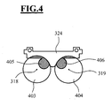
- Fig. 4 shows a section of the reflective panel 324 along the line IV - IV Fig. 3
- the illumination beam path at the reflex stop 324 has an optical axis 318 and a optical axis 319 with cross-sectional areas 403 and 404. From the illumination beam path in the areas 405 and 406 by means of the reflective aperture 324 those illumination beams are shadowed, which after deflecting by the deflecting element 113 by reflections on the microscope main objective 101 in Fig. 1 Induce scattered light, the about the magnification system 103 in the surgical microscope 100 from Fig. 1 so that the observational image visible to an observer in the binocular tube 104 is compromised.
- Fig. 5 shows a 3-dimensional view of a central unit 500 of the lighting device 110 from Fig. 1 , As far as the modules of the unit 500 in the FIGS. 1 . 2 . 3 or 4 can be seen, the same reference numerals are used to their name.
- the illumination unit unit 500 has a light guide end receptacle 501 that provides light for off-axis illumination.
- the unit 500 comprises a receptacle 502 for a light guide end, emerges from the light for near-axis illumination light.
- a rotary knob 503 is provided which can be rotated about an axis 504 corresponding to the double arrow 505.
- the rotary knob 503 is connected to a shaft 506 in which a first control cam 507, a second control cam 508 and a third control cam 509 is formed.
- the first control cam 507 is operatively connected to a first output unit 510, by means of which the diaphragm 302 is made Fig. 3 can be adjusted.
- the second control cam 508 acts on a second output unit 511, around the retinal protective shield 202 Fig. 2 to adjust.
- the third control cam 509 is in operative connection with a third output element 512 which forms the diaphragm 205 Fig. 2 controls.
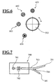
- the FIG. 6 shows various possible settings of the knob 503 Fig. 5 ,
- the setting 601 the beam path for off-axis illumination light is obstructed and only near-illumination light is guided to the object area.
- the setting 602 takes the Intensity of that illumination light, which is guided in the surgical microscope with off-axis course with respect to the optical axis of the observation beam path to the object area.
- both near-axis and off-axis illumination light is provided.
- the knob 503 can be moved to the position 603.
- the beam path for near-axis illumination light is interrupted and only off-axis illumination light is guided to the object area.
- a setting 604 is possible for the rotary knob 503.
- the beam path for near-axis illumination light is interrupted.
- illumination light is provided corresponding to the illumination beam path for off-axis illumination light, wherein the retinal protection diaphragm is switched on in the illumination beam path.
- the illumination device 110 of the surgical microscope 100 Fig. 1 is associated with a light source 700, which in Fig. 7 is shown.
- the light source 700 comprises a halogen lamp 701, whose light is fed via an optical unit 702 to a light guide 703.
- a light guide 703 has a branch 704 for providing illuminating light for off-axis illumination at a first exit end 201.
- the light guide has a second exit end 301, out of the light for near-axis illumination of the object area in the surgical microscope 100 Fig. 1 exit.
- the Fig. 8 shows the exit end 301 of the light guide 703. Exit end 301 is formed as a light exit unit having a first illumination pupil 314 and a second illumination pupil 315.
- Fig. 9 the exit end 201 of the light guide 703 is shown.
- the exit end 201 also acts as a light exit unit. Here, however, there is only one illumination pupil 901.
- the illumination device 110 of the in Fig. 1 shown operating microscope 100 allows extremely versatile illumination of the object area 105 of the Operation Microscope 100: By Adjusting the Aperture 302 Fig. 3 In the illumination beam path 111 for near-illumination light, the brightness of a red reflex caused on a patient's eye can be adjusted.
- the diaphragm 302 is placed in the illumination beam path 111 of the surgical microscope 100 so that when the diaphragm 302 is closed, the light field becomes uniformly darker without unilateral shadowing or diminishing of the illumination field diameter.
- the diaphragm 205 is in turn placed in the beam path 112 in such a way that the light field caused by the beam path 112 in the object region 105 of the surgical microscope is uniformly darker when it is dark, without unilateral shading or the light field diameter being reduced.
- the illumination of the object area exclusively with achsnahem illumination light from the illumination beam path 111 from Fig. 1 is particularly advantageous when using video documentation systems. If no off-axis illumination light reaches the subject area, a patient's eye is prevented from scattering excess light on its skelera. This results in a good image contrast and it is avoided that due to an automatic adjustment of exposure time or amplification by means of a camera captured images of a patient's eye in the area of the pupil are too dark and too low contrast.
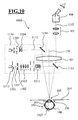
- the Fig. 10 shows another surgical microscope 1000.
- the assemblies of the surgical microscope 100 from Fig. 1 same, these are in Fig. 10 identical reference numerals as in Fig. 1 assigned.
- the surgical microscope 1000 is in turn designed as an ophthalmic surgical microscope and is particularly suitable for Examination of a patient's eye 106 arranged in an object area 105.
- the object plane 355 lies in the region of the cornea 361 of the patient's eye 106, ie the surgical microscope is focused on the cornea of the patient's eye.
- the surgical microscope 1000 includes a lighting device 1110, which provides a first illumination beam path 1111 for near-axis illumination with respect to the stereoscopic observation beam path 102 and a second illumination beam path 1112 for off-axis illumination of the object region.
- the illumination device 1110 comprises a light-transmissive mirror 1113, which acts as a first deflection element to superimpose illumination light on the stereoscopic observation beam path 102 on the side of the microscope main objective 101 assigned to the object.
- the illumination device 1110 includes a mirror 1114 as the second deflection element, which directs the illumination light remote from the axis to the object region 105 through the microscope main objective 101.
- the basic structure of the illumination device 1110 corresponds to that of the illumination device 110 Fig. 1
- illumination optics 1303, 1311 in the illumination device 1110 a light exit unit 1301 in a light exit plane 1313 in the first illumination beam path 1111 is imaged by an adjustable aperture stop 1302 into a first image plane 350.
- the second illumination beam path 1112 contains a field diaphragm 1203, which is imaged with illumination optics 1204 through the microscope main objective into a second image plane 250 different from the first image plane 350.
- the illumination optics 1302, 1303, 1311 is designed so that an illumination spot 1322 is generated on the retina 363 of the patient's eye 106, the diameter of which is in the range 0.5 mm to 1.5 mm.
- FIG. 11 Another surgical microscope is in Fig. 11 shown.
- the surgical microscope 2000 in Fig. 11 has 1000 according to the surgical microscope Fig. 10 a microscope main lens 101 with an optical axis 150, which is a stereoscopic Observation beam 102 is penetrated. It allows an observer via an enlargement system 103 and a binocular tube 104 to examine an object region 105 in an object plane 355.
- the surgical microscope 2000 is also designed as an ophthalmic surgical microscope for examining a patient's eye 106.
- the surgical microscope 2000 includes a lighting device 2110, which provides a first illumination beam path 2111 for near-axis illumination and a second illumination beam path 2112 for achs distant illumination of the object area with respect to the stereoscopic observation beam path 102.
- the illumination device 2110 comprises a light-transmissive mirror 2113, which acts as a first deflection element to superimpose illumination light on the stereoscopic observation beam path 102 on the side of the microscope main objective 101 assigned to the object.
- the illumination device 2110 includes a mirror 2114 as the second deflection element, which directs the illumination light away from the microscope main objective 101 past the object region 105.
- the operation of the illumination device 2110 corresponds to that of the illumination device 110 Fig. 1 or 1110 off Fig. 10
- a light exit unit 2301 with a light exit plane 2323 in the first illumination beam path 2111 is imaged by an adjustable aperture stop 2302 into a first image plane 350.
- the second illumination beam path 2112 contains a field diaphragm 2203, which in turn is imaged with an illumination optical unit 2204 into a second image plane 250 that is different from the first image plane 350.
- the illumination optics 2302, 2303, 2311 in the first illumination beam path is likewise designed so that an illumination spot 2322 is generated on the retina 363 of the patient's eye 106, the diameter of which is in the range 0.5 mm to 1.5 mm.
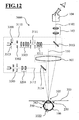
- the Fig. 12 shows a surgical microscope 3000.
- the surgical microscope 3000 has a microscope main objective 101 with an optical axis 150, which is penetrated by a stereoscopic observation beam 102. It allows one Observant on a magnification system 103 and a binocular tube 104 to examine an object area 105 in an object plane 355.
- the surgical microscope 3000 is likewise designed as an ophthalmic surgical microscope and is therefore particularly suitable for examining a patient's eye 106.
- the surgical microscope 3000 in turn contains, like the surgical microscopes described above, a lighting device 3110, which provides a first illumination beam path 3111 for near-axis illumination and a second illumination beam path 3112 for achs distant illumination of the object area with respect to the stereoscopic observation beam path 102.
- the illumination device 3110 comprises a light-permeable mirror 3113, which acts as a first deflection element to superimpose illumination light on the stereoscopic observation beam path 102 through the microscope main objective 101.
- the illumination device 3110 contains a mirror 3114 as the second deflection element, which directs the illumination light away from the microscope main objective 101 past the object region 105.
- a light exit unit 3301 with a light exit plane 3323 in the first illumination beam path 3111 is imaged into a first image plane 350.
- the second illumination beam path 3112 contains a field diaphragm 3203, which in turn is imaged by illumination optics 3204 into a second image plane 250 different from the first image plane 350.
- the illumination optics 3302, 3303, 3311 and 101 in the first illumination beam path 3111 of the illumination device 3110 is designed so that an illumination spot 3322 is generated on the retina 363 of the patient's eye 106, whose diameter is in the range 0.5 mm to 1.5 mm.
- a surgical microscope having a plurality of stereoscopic observation beam paths, such as a main observation stereoscopic observation beam path and a co-observation stereoscopic observation beam path
- a first illumination beam path providing illuminating light guided to the object section with a plurality of optical axes which correspond to the optical axes of the observation beam paths.
Landscapes
- Physics & Mathematics (AREA)
- Health & Medical Sciences (AREA)
- Chemical & Material Sciences (AREA)
- Analytical Chemistry (AREA)
- General Physics & Mathematics (AREA)
- Optics & Photonics (AREA)
- Life Sciences & Earth Sciences (AREA)
- General Health & Medical Sciences (AREA)
- Surgery (AREA)
- Ophthalmology & Optometry (AREA)
- Biophysics (AREA)
- Engineering & Computer Science (AREA)
- Biomedical Technology (AREA)
- Heart & Thoracic Surgery (AREA)
- Medical Informatics (AREA)
- Molecular Biology (AREA)
- Animal Behavior & Ethology (AREA)
- Public Health (AREA)
- Veterinary Medicine (AREA)
- Microscoopes, Condenser (AREA)
Claims (26)
- Microscope d'opération (100, 1000, 2000, 3000) doté d'un dispositif d'éclairage (110, 1110, 2110, 3110)- dans lequel le dispositif d'éclairage (110, 1110, 2110, 3110) peut fournir de la lumière d'éclairage pour l'espace objet (105) au moyen d'un premier chemin de faisceau d'éclairage (111, 1111, 2111, 3111) et de la lumière d'éclairage pour l'espace objet au moyen d'un deuxième chemin de faisceau d'éclairage (112, 1112, 2112, 3112),- une première unité de sortie de lumière (301, 1301, 2301, 3301) étant prévue pour fournir de la lumière au premier chemin de faisceau d'éclairage (111, 1111, 2111, 3111) ; et- un diaphragme du champ d'éclairage (203, 1203, 2203, 3203) étant disposé sur le deuxième chemin de faisceau d'éclairage (112, 1112, 2112, 3112),- le premier chemin de faisceau d'éclairage (111, 1111, 2111, 3111) comportant une optique d'éclairage (302, 303, 306, 310, 311, 101, 1302, 1303, 1311, 2302, 2303, 2311, 3302, 3303, 3311, 101) qui reproduit dans un premier plan image (350) à l'infini, le plan de sortie de la lumière (313, 1313, 2323, 3323) de la première unité de sortie de lumière (301, 1301, 2301, 3301) ou un plan conjugué du plan de sortie de la lumière (313, 1313, 2323, 3323),- une optique d'éclairage (204, 101, 1204, 101, 2204, 3204) étant prévue sur le deuxième chemin de faisceau d'éclairage (112, 1112, 2112, 3112) qui reproduit le diaphragme du champ d'éclairage (203, 1203, 2203, 3203) dans un deuxième plan image (250) différent du premier plan image (350),- le premier chemin de faisceau d'éclairage (111, 1111, 2111, 3111) étant acheminé vers l'espace objet (105) selon un tracé proche de l'axe par rapport à au moins un axe optique (161) du chemin de faisceau d'observation (102) du microscope d'opération,- le deuxième chemin de faisceau d'éclairage (112, 1112, 2112, 3112) étant acheminé vers l'espace objet (105) selon un tracé éloigné de l'axe par rapport à au moins un axe optique (161) du chemin de faisceau d'observation (102) du microscope d'opération,- le deuxième plan image (250), dans lequel se trouve l'image du diaphragme du champ d'éclairage (203) sur le deuxième chemin de faisceau d'éclairage (112), se trouvant dans la proximité du plan objet (355) ou coïncidant avec le plan objet (355) du microscope d'opération (100).
- Microscope d'opération selon la revendication 1, caractérisé en ce que le premier chemin de faisceau d'éclairage (111, 3111) traverse l'objectif principal (101) du microscope.
- Microscope d'opération selon la revendication 2, caractérisé en ce qu'un premier élément de déviation (113, 3113) est prévu pour diriger la lumière d'éclairage à travers l'objectif principal (101) du microscope vers l'espace objet (105).
- Microscope d'opération selon la revendication 3, caractérisé en ce que le premier élément de déviation (113, 3113) est réalisé sous la forme d'un miroir semi-transparent traversé par un chemin de faisceau d'observation (102) du microscope d'opération (100).
- Microscope d'opération selon la revendication 4, caractérisé en ce que le miroir semi-transparent (113, 3113) est réalisé sous la forme d'un séparateur de faisceau physique ou d'un séparateur de faisceau géométrique.
- Microscope d'opération selon la revendication 3, 4 ou 5, caractérisé en ce que le premier élément de déviation (113, 3113) sert à superposer de manière coaxiale de la lumière d'éclairage à un chemin de faisceau d'observation stéréoscopique (102).
- Microscope d'opération selon la revendication 6, caractérisé en ce que le premier élément de déviation (113, 3113) superpose de manière coaxiale de la lumière d'éclairage à un chemin de faisceau d'observation gauche et à un chemin de faisceau d'observation droit (102).
- Microscope d'opération selon une des revendications 2 à 7, caractérisé en ce qu'un deuxième élément de déviation (114, 1114) est prévu pour diriger la lumière d'éclairage à travers l'objectif principal (101) du microscope vers l'espace objet (105).
- Microscope d'opération selon une des revendications 1 à 8, caractérisé en ce qu'un autre diaphragme (202) est disposé près du diaphragme du champ d'éclairage (203).
- Microscope d'opération selon la revendication 9, caractérisé en ce qu'on peut modifier l'ouverture de l'autre diaphragme (202).
- Microscope d'opération selon la revendication 9 ou 10, caractérisé en ce que l'autre diaphragme (202) est réalisé comme diaphragme de protection de la rétine.
- Microscope d'opération selon une des revendications 1 à 11, caractérisé en ce qu'un diaphragme d'ouverture (205) est disposé sur le deuxième chemin de faisceau d'éclairage (112).
- Microscope d'opération selon la revendication 12, caractérisé en ce que le diaphragme d'ouverture (205) dispose d'une ouverture de diaphragme réglable.
- Microscope d'opération selon une des revendications 1 à 13, caractérisé en ce qu'un diaphragme (302) est réalisé sur le premier chemin de faisceau d'éclairage (111) avec une ouverture de diaphragme fixe réglable pour modifier la quantité de lumière sur le premier chemin de faisceau d'éclairage (111).
- Microscope d'opération selon la revendication 14, dans le mesure où la revendication 14 se réfère à la revendication 13 et la revendication 13 se réfère à la revendication 12, caractérisé en ce qu'un élément de manoeuvre commun (503) pouvant être actionné par l'utilisateur est prévu pour le réglage du diaphragme (202) sur le deuxième chemin de faisceau d'éclairage (112) et/ou du diaphragme d'ouverture (205) sur le deuxième chemin de faisceau d'éclairage (112) et/ou du diaphragme (302) sur le premier chemin de faisceau d'éclairage (111).
- Microscope d'opération selon la revendication 15, caractérisé en ce que l'élément de manoeuvre pouvant être actionné par l'utilisateur est réalisé sous forme de bouton rotatif (503).
- Microscope d'opération selon la revendication 16, caractérisé en ce que le bouton rotatif (503) est accouplé à une unité d'arbre (506) se trouvant en liaison active avec le diaphragme (302) sur le premier chemin de faisceau d'éclairage (111) par l'intermédiaire d'une première came (507) ainsi que d'une première unité d'entraînement (510), qui se trouve en liaison active avec le diaphragme (202) sur le deuxième chemin de faisceau d'éclairage (112) par l'intermédiaire d'une deuxième came (508) ainsi que d'une deuxième unité d'entraînement (511) et qui se trouve en liaison active avec le diaphragme d'ouverture (205) par l'intermédiaire d'une troisième came (509) ainsi que d'une troisième unité d'entraînement (512).
- Microscope d'opération selon une des revendications 1 à 17, caractérisé en ce qu'une source lumineuse commune (700) est attribuée au premier chemin de faisceau d'éclairage (111) et au deuxième chemin de faisceau d'éclairage (112).
- Microscope d'opération selon la revendication 18, caractérisé en ce qu'un conduit de lumière (703) avec bifurcation (704) est prévu pour acheminer la lumière de la source lumineuse commune (700) vers le premier chemin de faisceau d'éclairage (111) et le deuxième chemin de faisceau d'éclairage (112).
- Microscope d'opération selon la revendication 19, caractérisé en ce que le conduit de lumière (703) comporte la première unité de sortie de lumière (301) et une deuxième unité de sortie de lumière (201).
- Microscope d'opération selon une des revendications 1 à 20, caractérisé en ce qu'une première pupille d'éclairage (314) et une deuxième pupille d'éclairage (315) sont réalisées dans la première unité de sortie de lumière (301).
- Microscope d'opération selon la revendication 20 ou la revendication 21, caractérisé en ce qu'une seule pupille d'éclairage (901) est réalisée dans la deuxième unité de sortie de lumière (201).
- Microscope d'opération selon une des revendications 1 à 22, caractérisé en ce qu'un diaphragme reflex (324) est prévu sur le premier chemin de faisceau d'éclairage (111) qui éclipse les rayons d'éclairage générant par réflexion sur les éléments optiques dans le microscope d'opération, de la lumière diffuse dans les chemins de faisceaux d'observation du microscope d'opération (100).
- Microscope d'opération selon la revendication 23, caractérisé en ce que le diaphragme reflex (324) est disposé de telle sorte qu'aucun rayon d'observation n'est occulté dans le microscope d'opération et que le diaphragme reflex (324) n'engendre aucune coupure de l'image du diaphragme du champ d'éclairage (203) dans le deuxième plan image (250).
- Microscope d'opération selon une des revendications 1 à 24, caractérisé en ce que le dispositif d'éclairage (110, 1110, 2110, 3110) est réalisé de telle sorte qu'une tache d'éclairage (322, 323) d'un diamètre situé dans la plage de 0,5 mm à 1,5 mm puisse être générée par la lumière d'éclairage provenant du premier chemin de faisceau d'éclairage (111, 1111, 2111, 3111) sur la rétine (363) d'un oeil idéal (106) de patient.
- Microscope d'opération selon la revendication 25, caractérisé en ce que le dispositif d'éclairage (110, 1110, 2110, 3110) est réalisé de telle sorte que deux taches d'éclairage chacune d'un diamètre situé dans la plage de 0,5 mm à 1,5 mm puissent être générées par la lumière d'éclairage provenant du premier chemin de faisceau d'éclairage (111, 1111, 2111, 3111) sur la rétine (363) d'un oeil idéal (106) de patient.
Applications Claiming Priority (2)
| Application Number | Priority Date | Filing Date | Title |
|---|---|---|---|
| DE102007025606 | 2007-05-31 | ||
| DE102007041003A DE102007041003A1 (de) | 2007-05-31 | 2007-08-29 | Operationsmikroskop mit Beleuchtungseinrichtung |
Publications (2)
| Publication Number | Publication Date |
|---|---|
| EP1997423A1 EP1997423A1 (fr) | 2008-12-03 |
| EP1997423B1 true EP1997423B1 (fr) | 2011-07-06 |
Family
ID=39643166
Family Applications (1)
| Application Number | Title | Priority Date | Filing Date |
|---|---|---|---|
| EP08156255A Active EP1997423B1 (fr) | 2007-05-31 | 2008-05-15 | Microscope d'opération doté d'un dispositif d'éclairage |
Country Status (1)
| Country | Link |
|---|---|
| EP (1) | EP1997423B1 (fr) |
Cited By (1)
| Publication number | Priority date | Publication date | Assignee | Title |
|---|---|---|---|---|
| EP2960704A1 (fr) | 2014-06-26 | 2015-12-30 | Carl Zeiss Meditec AG | Dispositif d'éclairage d'un microscope opératoire |
Families Citing this family (6)
| Publication number | Priority date | Publication date | Assignee | Title |
|---|---|---|---|---|
| DE102012203266A1 (de) | 2012-03-01 | 2013-09-05 | Leica Microsystems (Schweiz) Ag | Mikroskop mit schaltbarem Dokumentations-Strahlengang |
| DE102013226288A1 (de) | 2013-12-17 | 2015-06-18 | Carl Zeiss Meditec Ag | Operationsmikroskop |
| DE102013226784A1 (de) * | 2013-12-19 | 2015-06-25 | Leica Microsysteme (Schweiz) AG | Operationsmikroskop |
| CN107911909A (zh) * | 2017-12-14 | 2018-04-13 | 苏州西默医疗科技有限公司 | 一种手术显微镜及其照明色温连续可调的方法 |
| US12016798B2 (en) * | 2019-09-10 | 2024-06-25 | Carl Zeiss Meditec Ag | Methods for characterizing a laser beam of a laser processing system, diaphragm assembly and laser processing system |
| CN111474699B (zh) * | 2020-04-09 | 2022-08-30 | 浙江未来技术研究院(嘉兴) | 一种可编程孔径的手术显微镜 |
Family Cites Families (8)
| Publication number | Priority date | Publication date | Assignee | Title |
|---|---|---|---|---|
| DE3339172A1 (de) | 1983-10-28 | 1985-05-15 | Fa. Carl Zeiss, 7920 Heidenheim | Lichtfalle fuer augenuntersuchungsgeraete |
| DE4344770A1 (de) | 1993-12-28 | 1995-06-29 | Leica Ag | Schaltbare Beleuchtungseinrichtung für ein Operationsmikroskop |
| JPH08257037A (ja) | 1995-03-20 | 1996-10-08 | Nikon Corp | 手術用顕微鏡 |
| JP3062542U (ja) * | 1999-07-01 | 1999-10-08 | 株式会社オービック・ビジネス・コンサルタント | 複数の通信プログラムに対応したエレクトロニック・バンキング装置 |
| DE59902878D1 (de) | 1999-12-15 | 2002-10-31 | Moeller Wedel Gmbh | Beleuchtungseinrichtung für ein Operationsmikroskop |
| EP1410754B1 (fr) * | 2002-10-16 | 2006-05-24 | Möller-Wedel GmbH | Microscope chirurgical à dispositif d'illumination |
| DE10304267B9 (de) * | 2003-02-03 | 2005-12-15 | Carl Zeiss | Augenchirurgie-Mikroskopiesystem |
| DE202004019849U1 (de) | 2004-12-23 | 2005-02-24 | Leica Microsystems (Schweiz) Ag | Beleuchtungseinrichtung für ein Operationsmikroskop in der Augenchirurgie |
-
2008
- 2008-05-15 EP EP08156255A patent/EP1997423B1/fr active Active
Cited By (2)
| Publication number | Priority date | Publication date | Assignee | Title |
|---|---|---|---|---|
| EP2960704A1 (fr) | 2014-06-26 | 2015-12-30 | Carl Zeiss Meditec AG | Dispositif d'éclairage d'un microscope opératoire |
| DE102014212372A1 (de) | 2014-06-26 | 2015-12-31 | Carl Zeiss Meditec Ag | Beleuchtungseinrichtung eines Operationsmikroskops |
Also Published As
| Publication number | Publication date |
|---|---|
| EP1997423A1 (fr) | 2008-12-03 |
Similar Documents
| Publication | Publication Date | Title |
|---|---|---|
| DE102007041003A1 (de) | Operationsmikroskop mit Beleuchtungseinrichtung | |
| DE102009036913B4 (de) | Operationsmikroskop mit Beleuchtungseinrichtung | |
| DE102016001659B4 (de) | Augenoperationsmikroskop und Augenoperationszusatzgerät | |
| DE102016203473B4 (de) | Augenmikroskop | |
| DE102016203487B4 (de) | Augenmikroskopsystem | |
| EP1997423B1 (fr) | Microscope d'opération doté d'un dispositif d'éclairage | |
| EP1955103B1 (fr) | Microscope pour chirurgie ophthalmologique | |
| EP2452616B1 (fr) | Dispositif d'observation | |
| DE102009017710B4 (de) | Optisches Beobachtungsgerät und Verfahren zum Gewährleisten einer gleich bleibenden Beleuchtungsintensität bei einem Wechsel der Farbtemperatur der Beleuchtung | |
| DE102011088038B4 (de) | Operationsmikroskopsystem für die Ophthalmologie und zugehörige Detektionseinheit | |
| DE102005032501A1 (de) | Vorrichtung zur Untersuchung vorderer und hinterer Augenabschnitte | |
| EP1455215B2 (fr) | Dispositif d'illumination pour un microscope | |
| EP1889567A2 (fr) | Module d'ophtalmoscopie pour un microscope d'opération | |
| DE102012221955A1 (de) | Beleuchtungseinrichtung für ein Operationsmikroskop | |
| DE10144067A1 (de) | Prismenkonstruktion für Simultane 0 DEG - und Schräg-Beleuchtung eines Stereo-Operationsmikroskops | |
| DE102011114523A1 (de) | Modul zur Weiterleitung eines Lichtstrahls | |
| EP1891890A1 (fr) | Appareil optique, utilisation d'un appareil optique selon l'invention tout comme procédé destiné à bloquer les reflets sur une trajectoire de faisceau d'observation d'un appareil optique | |
| DE2914675A1 (de) | Lichtkoagulator | |
| WO2005039404A1 (fr) | Unite d'eclairage pour retinographe et/ou ophtalmoscope | |
| DE102011085527B4 (de) | Beleuchtungseinrichtung für ein Stereomikroskop, insbesondere Operationsmikroskop | |
| DE2202120A1 (de) | Optische einrichtung zur erzeugung von koagulationen, vorzugsweise auf der netzhaut eines auges | |
| DE202007012431U1 (de) | Operationsmikroskop mit einer Beleuchtungseinrichtung | |
| DE102021107297A1 (de) | Optisches System für die Augenchirurgie und Verfahren zum Vermeiden einer zu hohen Lichtintensität an einem digitalen Bildsensor eines Operationsmikroskops | |
| DE102024112777B4 (de) | Optisches Beobachtungsgerät und Verfahren zum Versehen eines optischen Beobachtungsgerätes mit einem Laserschutzfilter | |
| DE19932643A1 (de) | Operationsmikroskop |
Legal Events
| Date | Code | Title | Description |
|---|---|---|---|
| PUAI | Public reference made under article 153(3) epc to a published international application that has entered the european phase |
Free format text: ORIGINAL CODE: 0009012 |
|
| AK | Designated contracting states |
Kind code of ref document: A1 Designated state(s): AT BE BG CH CY CZ DE DK EE ES FI FR GB GR HR HU IE IS IT LI LT LU LV MC MT NL NO PL PT RO SE SI SK TR |
|
| AX | Request for extension of the european patent |
Extension state: AL BA MK RS |
|
| 17P | Request for examination filed |
Effective date: 20090116 |
|
| 17Q | First examination report despatched |
Effective date: 20090220 |
|
| AKX | Designation fees paid |
Designated state(s): DE ES FR GB IT |
|
| GRAP | Despatch of communication of intention to grant a patent |
Free format text: ORIGINAL CODE: EPIDOSNIGR1 |
|
| GRAS | Grant fee paid |
Free format text: ORIGINAL CODE: EPIDOSNIGR3 |
|
| GRAA | (expected) grant |
Free format text: ORIGINAL CODE: 0009210 |
|
| AK | Designated contracting states |
Kind code of ref document: B1 Designated state(s): DE ES FR GB IT |
|
| REG | Reference to a national code |
Ref country code: GB Ref legal event code: FG4D Free format text: NOT ENGLISH |
|
| REG | Reference to a national code |
Ref country code: DE Ref legal event code: R096 Ref document number: 502008004104 Country of ref document: DE Effective date: 20110825 |
|
| REG | Reference to a national code |
Ref country code: ES Ref legal event code: FG2A Ref document number: 2366760 Country of ref document: ES Kind code of ref document: T3 Effective date: 20111025 |
|
| PLBE | No opposition filed within time limit |
Free format text: ORIGINAL CODE: 0009261 |
|
| STAA | Information on the status of an ep patent application or granted ep patent |
Free format text: STATUS: NO OPPOSITION FILED WITHIN TIME LIMIT |
|
| 26N | No opposition filed |
Effective date: 20120411 |
|
| REG | Reference to a national code |
Ref country code: DE Ref legal event code: R097 Ref document number: 502008004104 Country of ref document: DE Effective date: 20120411 |
|
| REG | Reference to a national code |
Ref country code: FR Ref legal event code: PLFP Year of fee payment: 8 |
|
| REG | Reference to a national code |
Ref country code: FR Ref legal event code: PLFP Year of fee payment: 9 |
|
| REG | Reference to a national code |
Ref country code: FR Ref legal event code: PLFP Year of fee payment: 10 |
|
| REG | Reference to a national code |
Ref country code: FR Ref legal event code: PLFP Year of fee payment: 11 |
|
| P01 | Opt-out of the competence of the unified patent court (upc) registered |
Effective date: 20230530 |
|
| PGFP | Annual fee paid to national office [announced via postgrant information from national office to epo] |
Ref country code: GB Payment date: 20240521 Year of fee payment: 17 |
|
| PGFP | Annual fee paid to national office [announced via postgrant information from national office to epo] |
Ref country code: ES Payment date: 20240626 Year of fee payment: 17 |
|
| PGFP | Annual fee paid to national office [announced via postgrant information from national office to epo] |
Ref country code: IT Payment date: 20240524 Year of fee payment: 17 |
|
| PGFP | Annual fee paid to national office [announced via postgrant information from national office to epo] |
Ref country code: DE Payment date: 20250521 Year of fee payment: 18 |
|
| PGFP | Annual fee paid to national office [announced via postgrant information from national office to epo] |
Ref country code: FR Payment date: 20250528 Year of fee payment: 18 |
|
| GBPC | Gb: european patent ceased through non-payment of renewal fee |
Effective date: 20250515 |
|
| PG25 | Lapsed in a contracting state [announced via postgrant information from national office to epo] |
Ref country code: GB Free format text: LAPSE BECAUSE OF NON-PAYMENT OF DUE FEES Effective date: 20250515 |
|
| PG25 | Lapsed in a contracting state [announced via postgrant information from national office to epo] |
Ref country code: IT Free format text: LAPSE BECAUSE OF NON-PAYMENT OF DUE FEES Effective date: 20250515 |