EP1997434B1 - Blutuntersuchungsvorrichtung - Google Patents
Blutuntersuchungsvorrichtung Download PDFInfo
- Publication number
- EP1997434B1 EP1997434B1 EP07739361.9A EP07739361A EP1997434B1 EP 1997434 B1 EP1997434 B1 EP 1997434B1 EP 07739361 A EP07739361 A EP 07739361A EP 1997434 B1 EP1997434 B1 EP 1997434B1
- Authority
- EP
- European Patent Office
- Prior art keywords
- blood
- battery
- power supply
- section
- skin
- Prior art date
- Legal status (The legal status is an assumption and is not a legal conclusion. Google has not performed a legal analysis and makes no representation as to the accuracy of the status listed.)
- Not-in-force
Links
- 239000008280 blood Substances 0.000 title claims description 412
- 210000004369 blood Anatomy 0.000 title claims description 412
- 238000007689 inspection Methods 0.000 title 1
- 238000009534 blood test Methods 0.000 claims description 182
- 238000012360 testing method Methods 0.000 claims description 51
- 238000000034 method Methods 0.000 claims description 27
- 230000008859 change Effects 0.000 claims description 18
- 210000003491 skin Anatomy 0.000 description 240
- 238000005259 measurement Methods 0.000 description 59
- 238000001514 detection method Methods 0.000 description 47
- 239000000758 substrate Substances 0.000 description 28
- 239000013078 crystal Substances 0.000 description 26
- 239000000463 material Substances 0.000 description 24
- 125000006850 spacer group Chemical group 0.000 description 20
- JNDMLEXHDPKVFC-UHFFFAOYSA-N aluminum;oxygen(2-);yttrium(3+) Chemical compound [O-2].[O-2].[O-2].[Al+3].[Y+3] JNDMLEXHDPKVFC-UHFFFAOYSA-N 0.000 description 19
- 229910019901 yttrium aluminum garnet Inorganic materials 0.000 description 19
- XLYOFNOQVPJJNP-UHFFFAOYSA-N water Substances O XLYOFNOQVPJJNP-UHFFFAOYSA-N 0.000 description 17
- WQZGKKKJIJFFOK-GASJEMHNSA-N Glucose Natural products OC[C@H]1OC(O)[C@H](O)[C@@H](O)[C@@H]1O WQZGKKKJIJFFOK-GASJEMHNSA-N 0.000 description 16
- 239000008103 glucose Substances 0.000 description 16
- 230000003287 optical effect Effects 0.000 description 16
- 239000000306 component Substances 0.000 description 14
- NOESYZHRGYRDHS-UHFFFAOYSA-N insulin Chemical compound N1C(=O)C(NC(=O)C(CCC(N)=O)NC(=O)C(CCC(O)=O)NC(=O)C(C(C)C)NC(=O)C(NC(=O)CN)C(C)CC)CSSCC(C(NC(CO)C(=O)NC(CC(C)C)C(=O)NC(CC=2C=CC(O)=CC=2)C(=O)NC(CCC(N)=O)C(=O)NC(CC(C)C)C(=O)NC(CCC(O)=O)C(=O)NC(CC(N)=O)C(=O)NC(CC=2C=CC(O)=CC=2)C(=O)NC(CSSCC(NC(=O)C(C(C)C)NC(=O)C(CC(C)C)NC(=O)C(CC=2C=CC(O)=CC=2)NC(=O)C(CC(C)C)NC(=O)C(C)NC(=O)C(CCC(O)=O)NC(=O)C(C(C)C)NC(=O)C(CC(C)C)NC(=O)C(CC=2NC=NC=2)NC(=O)C(CO)NC(=O)CNC2=O)C(=O)NCC(=O)NC(CCC(O)=O)C(=O)NC(CCCNC(N)=N)C(=O)NCC(=O)NC(CC=3C=CC=CC=3)C(=O)NC(CC=3C=CC=CC=3)C(=O)NC(CC=3C=CC(O)=CC=3)C(=O)NC(C(C)O)C(=O)N3C(CCC3)C(=O)NC(CCCCN)C(=O)NC(C)C(O)=O)C(=O)NC(CC(N)=O)C(O)=O)=O)NC(=O)C(C(C)CC)NC(=O)C(CO)NC(=O)C(C(C)O)NC(=O)C1CSSCC2NC(=O)C(CC(C)C)NC(=O)C(NC(=O)C(CCC(N)=O)NC(=O)C(CC(N)=O)NC(=O)C(NC(=O)C(N)CC=1C=CC=CC=1)C(C)C)CC1=CN=CN1 NOESYZHRGYRDHS-UHFFFAOYSA-N 0.000 description 12
- 239000013307 optical fiber Substances 0.000 description 12
- 239000005871 repellent Substances 0.000 description 12
- 238000010586 diagram Methods 0.000 description 10
- 239000000835 fiber Substances 0.000 description 9
- 239000012503 blood component Substances 0.000 description 7
- 238000011088 calibration curve Methods 0.000 description 7
- 239000003990 capacitor Substances 0.000 description 7
- 239000003153 chemical reaction reagent Substances 0.000 description 7
- 230000007423 decrease Effects 0.000 description 7
- 230000005284 excitation Effects 0.000 description 7
- 229920000139 polyethylene terephthalate Polymers 0.000 description 7
- 239000005020 polyethylene terephthalate Substances 0.000 description 7
- -1 potassium ferricyanide Chemical compound 0.000 description 7
- 102000004877 Insulin Human genes 0.000 description 6
- 108090001061 Insulin Proteins 0.000 description 6
- 239000003795 chemical substances by application Substances 0.000 description 6
- 229940125396 insulin Drugs 0.000 description 6
- 230000010355 oscillation Effects 0.000 description 6
- 238000002360 preparation method Methods 0.000 description 6
- 229920005989 resin Polymers 0.000 description 6
- 239000011347 resin Substances 0.000 description 6
- 230000009471 action Effects 0.000 description 5
- 239000004020 conductor Substances 0.000 description 5
- 206010012601 diabetes mellitus Diseases 0.000 description 5
- 238000002347 injection Methods 0.000 description 5
- 239000007924 injection Substances 0.000 description 5
- 230000001877 deodorizing effect Effects 0.000 description 4
- 210000004207 dermis Anatomy 0.000 description 4
- 230000000694 effects Effects 0.000 description 4
- 210000002615 epidermis Anatomy 0.000 description 4
- 238000005192 partition Methods 0.000 description 4
- 102000004190 Enzymes Human genes 0.000 description 3
- 108090000790 Enzymes Proteins 0.000 description 3
- 229910052691 Erbium Inorganic materials 0.000 description 3
- 238000010521 absorption reaction Methods 0.000 description 3
- 230000017531 blood circulation Effects 0.000 description 3
- UYAHIZSMUZPPFV-UHFFFAOYSA-N erbium Chemical compound [Er] UYAHIZSMUZPPFV-UHFFFAOYSA-N 0.000 description 3
- 238000003780 insertion Methods 0.000 description 3
- 230000037431 insertion Effects 0.000 description 3
- 239000004033 plastic Substances 0.000 description 3
- 229920003023 plastic Polymers 0.000 description 3
- 238000003825 pressing Methods 0.000 description 3
- 239000012780 transparent material Substances 0.000 description 3
- 229910052724 xenon Inorganic materials 0.000 description 3
- FHNFHKCVQCLJFQ-UHFFFAOYSA-N xenon atom Chemical compound [Xe] FHNFHKCVQCLJFQ-UHFFFAOYSA-N 0.000 description 3
- 229910052689 Holmium Inorganic materials 0.000 description 2
- WHXSMMKQMYFTQS-UHFFFAOYSA-N Lithium Chemical compound [Li] WHXSMMKQMYFTQS-UHFFFAOYSA-N 0.000 description 2
- KDLHZDBZIXYQEI-UHFFFAOYSA-N Palladium Chemical compound [Pd] KDLHZDBZIXYQEI-UHFFFAOYSA-N 0.000 description 2
- 239000004642 Polyimide Substances 0.000 description 2
- XUIMIQQOPSSXEZ-UHFFFAOYSA-N Silicon Chemical compound [Si] XUIMIQQOPSSXEZ-UHFFFAOYSA-N 0.000 description 2
- 238000004458 analytical method Methods 0.000 description 2
- 239000002585 base Substances 0.000 description 2
- HVYWMOMLDIMFJA-DPAQBDIFSA-N cholesterol Chemical compound C1C=C2C[C@@H](O)CC[C@]2(C)[C@@H]2[C@@H]1[C@@H]1CC[C@H]([C@H](C)CCCC(C)C)[C@@]1(C)CC2 HVYWMOMLDIMFJA-DPAQBDIFSA-N 0.000 description 2
- 239000012530 fluid Substances 0.000 description 2
- 239000011521 glass Substances 0.000 description 2
- 238000005534 hematocrit Methods 0.000 description 2
- KJZYNXUDTRRSPN-UHFFFAOYSA-N holmium atom Chemical compound [Ho] KJZYNXUDTRRSPN-UHFFFAOYSA-N 0.000 description 2
- 230000002209 hydrophobic effect Effects 0.000 description 2
- 125000002887 hydroxy group Chemical group [H]O* 0.000 description 2
- 238000009413 insulation Methods 0.000 description 2
- 230000001678 irradiating effect Effects 0.000 description 2
- 239000004973 liquid crystal related substance Substances 0.000 description 2
- 229910052744 lithium Inorganic materials 0.000 description 2
- 238000004519 manufacturing process Methods 0.000 description 2
- 230000033116 oxidation-reduction process Effects 0.000 description 2
- BASFCYQUMIYNBI-UHFFFAOYSA-N platinum Chemical compound [Pt] BASFCYQUMIYNBI-UHFFFAOYSA-N 0.000 description 2
- 229920001721 polyimide Polymers 0.000 description 2
- 230000008569 process Effects 0.000 description 2
- 238000012545 processing Methods 0.000 description 2
- 238000004080 punching Methods 0.000 description 2
- 230000002940 repellent Effects 0.000 description 2
- 239000010703 silicon Substances 0.000 description 2
- 229910052710 silicon Inorganic materials 0.000 description 2
- 239000000243 solution Substances 0.000 description 2
- 238000004544 sputter deposition Methods 0.000 description 2
- 238000003860 storage Methods 0.000 description 2
- 239000000126 substance Substances 0.000 description 2
- XOAAWQZATWQOTB-UHFFFAOYSA-N taurine Chemical compound NCCS(O)(=O)=O XOAAWQZATWQOTB-UHFFFAOYSA-N 0.000 description 2
- 238000002834 transmittance Methods 0.000 description 2
- JOYRKODLDBILNP-UHFFFAOYSA-N Ethyl urethane Chemical compound CCOC(N)=O JOYRKODLDBILNP-UHFFFAOYSA-N 0.000 description 1
- 241000447437 Gerreidae Species 0.000 description 1
- JVTAAEKCZFNVCJ-UHFFFAOYSA-M Lactate Chemical compound CC(O)C([O-])=O JVTAAEKCZFNVCJ-UHFFFAOYSA-M 0.000 description 1
- HBBGRARXTFLTSG-UHFFFAOYSA-N Lithium ion Chemical compound [Li+] HBBGRARXTFLTSG-UHFFFAOYSA-N 0.000 description 1
- PWHULOQIROXLJO-UHFFFAOYSA-N Manganese Chemical compound [Mn] PWHULOQIROXLJO-UHFFFAOYSA-N 0.000 description 1
- PXHVJJICTQNCMI-UHFFFAOYSA-N Nickel Chemical compound [Ni] PXHVJJICTQNCMI-UHFFFAOYSA-N 0.000 description 1
- 239000004698 Polyethylene Substances 0.000 description 1
- 239000004743 Polypropylene Substances 0.000 description 1
- 239000002253 acid Substances 0.000 description 1
- 229920000122 acrylonitrile butadiene styrene Polymers 0.000 description 1
- 230000001154 acute effect Effects 0.000 description 1
- 239000003513 alkali Substances 0.000 description 1
- 230000002421 anti-septic effect Effects 0.000 description 1
- 238000013459 approach Methods 0.000 description 1
- 239000007864 aqueous solution Substances 0.000 description 1
- 230000008901 benefit Effects 0.000 description 1
- 230000005540 biological transmission Effects 0.000 description 1
- 230000036770 blood supply Effects 0.000 description 1
- 210000004204 blood vessel Anatomy 0.000 description 1
- 230000036760 body temperature Effects 0.000 description 1
- 235000012000 cholesterol Nutrition 0.000 description 1
- 238000004891 communication Methods 0.000 description 1
- 238000007796 conventional method Methods 0.000 description 1
- 230000008878 coupling Effects 0.000 description 1
- 238000010168 coupling process Methods 0.000 description 1
- 238000005859 coupling reaction Methods 0.000 description 1
- 229940021171 curative drug Drugs 0.000 description 1
- 239000002781 deodorant agent Substances 0.000 description 1
- 230000001419 dependent effect Effects 0.000 description 1
- 230000006866 deterioration Effects 0.000 description 1
- 238000007599 discharging Methods 0.000 description 1
- 238000006073 displacement reaction Methods 0.000 description 1
- 238000009826 distribution Methods 0.000 description 1
- 239000003814 drug Substances 0.000 description 1
- 238000001035 drying Methods 0.000 description 1
- 239000003822 epoxy resin Substances 0.000 description 1
- 230000004438 eyesight Effects 0.000 description 1
- 239000000446 fuel Substances 0.000 description 1
- PCHJSUWPFVWCPO-UHFFFAOYSA-N gold Chemical group [Au] PCHJSUWPFVWCPO-UHFFFAOYSA-N 0.000 description 1
- 229910052737 gold Inorganic materials 0.000 description 1
- 239000010931 gold Substances 0.000 description 1
- 238000007373 indentation Methods 0.000 description 1
- 238000001746 injection moulding Methods 0.000 description 1
- 150000002500 ions Chemical class 0.000 description 1
- 229910001416 lithium ion Inorganic materials 0.000 description 1
- VQHSOMBJVWLPSR-WUJBLJFYSA-N maltitol Chemical compound OC[C@H](O)[C@@H](O)[C@@H]([C@H](O)CO)O[C@H]1O[C@H](CO)[C@@H](O)[C@H](O)[C@H]1O VQHSOMBJVWLPSR-WUJBLJFYSA-N 0.000 description 1
- 229940035436 maltitol Drugs 0.000 description 1
- 235000010449 maltitol Nutrition 0.000 description 1
- 239000000845 maltitol Substances 0.000 description 1
- 229910052748 manganese Inorganic materials 0.000 description 1
- 239000011572 manganese Substances 0.000 description 1
- 239000000155 melt Substances 0.000 description 1
- 238000002156 mixing Methods 0.000 description 1
- 239000000203 mixture Substances 0.000 description 1
- 230000007935 neutral effect Effects 0.000 description 1
- 229910000652 nickel hydride Inorganic materials 0.000 description 1
- 229910052763 palladium Inorganic materials 0.000 description 1
- 239000005011 phenolic resin Substances 0.000 description 1
- 229910052697 platinum Inorganic materials 0.000 description 1
- 229920000647 polyepoxide Polymers 0.000 description 1
- 229920000573 polyethylene Polymers 0.000 description 1
- 229920000642 polymer Polymers 0.000 description 1
- 229920001155 polypropylene Polymers 0.000 description 1
- 229920000915 polyvinyl chloride Polymers 0.000 description 1
- 239000004800 polyvinyl chloride Substances 0.000 description 1
- 238000005070 sampling Methods 0.000 description 1
- 239000004065 semiconductor Substances 0.000 description 1
- 230000035939 shock Effects 0.000 description 1
- 210000000434 stratum corneum Anatomy 0.000 description 1
- 229960003080 taurine Drugs 0.000 description 1
- 229920005992 thermoplastic resin Polymers 0.000 description 1
- 229920001187 thermosetting polymer Polymers 0.000 description 1
- 238000007740 vapor deposition Methods 0.000 description 1
- 210000003462 vein Anatomy 0.000 description 1
- 230000003313 weakening effect Effects 0.000 description 1
Images


Classifications
-
- A—HUMAN NECESSITIES
- A61—MEDICAL OR VETERINARY SCIENCE; HYGIENE
- A61B—DIAGNOSIS; SURGERY; IDENTIFICATION
- A61B5/00—Measuring for diagnostic purposes; Identification of persons
- A61B5/15—Devices for taking samples of blood
- A61B5/157—Devices characterised by integrated means for measuring characteristics of blood
-
- A—HUMAN NECESSITIES
- A61—MEDICAL OR VETERINARY SCIENCE; HYGIENE
- A61B—DIAGNOSIS; SURGERY; IDENTIFICATION
- A61B5/00—Measuring for diagnostic purposes; Identification of persons
- A61B5/15—Devices for taking samples of blood
- A61B5/151—Devices specially adapted for taking samples of capillary blood, e.g. by lancets, needles or blades
-
- A—HUMAN NECESSITIES
- A61—MEDICAL OR VETERINARY SCIENCE; HYGIENE
- A61B—DIAGNOSIS; SURGERY; IDENTIFICATION
- A61B5/00—Measuring for diagnostic purposes; Identification of persons
- A61B5/14—Devices for taking samples of blood ; Measuring characteristics of blood in vivo, e.g. gas concentration within the blood, pH-value of blood
- A61B5/1405—Devices for taking blood samples
-
- A—HUMAN NECESSITIES
- A61—MEDICAL OR VETERINARY SCIENCE; HYGIENE
- A61B—DIAGNOSIS; SURGERY; IDENTIFICATION
- A61B5/00—Measuring for diagnostic purposes; Identification of persons
- A61B5/15—Devices for taking samples of blood
- A61B5/150007—Details
- A61B5/150015—Source of blood
- A61B5/150022—Source of blood for capillary blood or interstitial fluid
-
- A—HUMAN NECESSITIES
- A61—MEDICAL OR VETERINARY SCIENCE; HYGIENE
- A61B—DIAGNOSIS; SURGERY; IDENTIFICATION
- A61B5/00—Measuring for diagnostic purposes; Identification of persons
- A61B5/15—Devices for taking samples of blood
- A61B5/150007—Details
- A61B5/150053—Details for enhanced collection of blood or interstitial fluid at the sample site, e.g. by applying compression, heat, vibration, ultrasound, suction or vacuum to tissue; for reduction of pain or discomfort; Skin piercing elements, e.g. blades, needles, lancets or canulas, with adjustable piercing speed
- A61B5/150061—Means for enhancing collection
- A61B5/150076—Means for enhancing collection by heating
-
- A—HUMAN NECESSITIES
- A61—MEDICAL OR VETERINARY SCIENCE; HYGIENE
- A61B—DIAGNOSIS; SURGERY; IDENTIFICATION
- A61B5/00—Measuring for diagnostic purposes; Identification of persons
- A61B5/15—Devices for taking samples of blood
- A61B5/150007—Details
- A61B5/150053—Details for enhanced collection of blood or interstitial fluid at the sample site, e.g. by applying compression, heat, vibration, ultrasound, suction or vacuum to tissue; for reduction of pain or discomfort; Skin piercing elements, e.g. blades, needles, lancets or canulas, with adjustable piercing speed
- A61B5/150061—Means for enhancing collection
- A61B5/150099—Means for enhancing collection by negative pressure, other than vacuum extraction into a syringe by pulling on the piston rod or into pre-evacuated tubes
-
- A—HUMAN NECESSITIES
- A61—MEDICAL OR VETERINARY SCIENCE; HYGIENE
- A61B—DIAGNOSIS; SURGERY; IDENTIFICATION
- A61B5/00—Measuring for diagnostic purposes; Identification of persons
- A61B5/15—Devices for taking samples of blood
- A61B5/150007—Details
- A61B5/150053—Details for enhanced collection of blood or interstitial fluid at the sample site, e.g. by applying compression, heat, vibration, ultrasound, suction or vacuum to tissue; for reduction of pain or discomfort; Skin piercing elements, e.g. blades, needles, lancets or canulas, with adjustable piercing speed
- A61B5/150106—Means for reducing pain or discomfort applied before puncturing; desensitising the skin at the location where body is to be pierced
- A61B5/150145—Means for reducing pain or discomfort applied before puncturing; desensitising the skin at the location where body is to be pierced by negative pressure, e.g. suction, vacuum
-
- A—HUMAN NECESSITIES
- A61—MEDICAL OR VETERINARY SCIENCE; HYGIENE
- A61B—DIAGNOSIS; SURGERY; IDENTIFICATION
- A61B5/00—Measuring for diagnostic purposes; Identification of persons
- A61B5/15—Devices for taking samples of blood
- A61B5/150007—Details
- A61B5/150206—Construction or design features not otherwise provided for; manufacturing or production; packages; sterilisation of piercing element, piercing device or sampling device
- A61B5/150213—Venting means
-
- A—HUMAN NECESSITIES
- A61—MEDICAL OR VETERINARY SCIENCE; HYGIENE
- A61B—DIAGNOSIS; SURGERY; IDENTIFICATION
- A61B5/00—Measuring for diagnostic purposes; Identification of persons
- A61B5/15—Devices for taking samples of blood
- A61B5/150007—Details
- A61B5/150206—Construction or design features not otherwise provided for; manufacturing or production; packages; sterilisation of piercing element, piercing device or sampling device
- A61B5/150229—Pumps for assisting the blood sampling
-
- A—HUMAN NECESSITIES
- A61—MEDICAL OR VETERINARY SCIENCE; HYGIENE
- A61B—DIAGNOSIS; SURGERY; IDENTIFICATION
- A61B5/00—Measuring for diagnostic purposes; Identification of persons
- A61B5/15—Devices for taking samples of blood
- A61B5/150007—Details
- A61B5/150206—Construction or design features not otherwise provided for; manufacturing or production; packages; sterilisation of piercing element, piercing device or sampling device
- A61B5/150259—Improved gripping, e.g. with high friction pattern or projections on the housing surface or an ergonometric shape
-
- A—HUMAN NECESSITIES
- A61—MEDICAL OR VETERINARY SCIENCE; HYGIENE
- A61B—DIAGNOSIS; SURGERY; IDENTIFICATION
- A61B5/00—Measuring for diagnostic purposes; Identification of persons
- A61B5/15—Devices for taking samples of blood
- A61B5/150007—Details
- A61B5/150358—Strips for collecting blood, e.g. absorbent
-
- A—HUMAN NECESSITIES
- A61—MEDICAL OR VETERINARY SCIENCE; HYGIENE
- A61B—DIAGNOSIS; SURGERY; IDENTIFICATION
- A61B5/00—Measuring for diagnostic purposes; Identification of persons
- A61B5/15—Devices for taking samples of blood
- A61B5/150007—Details
- A61B5/150755—Blood sample preparation for further analysis, e.g. by separating blood components or by mixing
-
- A—HUMAN NECESSITIES
- A61—MEDICAL OR VETERINARY SCIENCE; HYGIENE
- A61B—DIAGNOSIS; SURGERY; IDENTIFICATION
- A61B5/00—Measuring for diagnostic purposes; Identification of persons
- A61B5/15—Devices for taking samples of blood
- A61B5/150007—Details
- A61B5/150954—Means for the detection of operative contact with patient, e.g. by temperature sensitive sensor
-
- A—HUMAN NECESSITIES
- A61—MEDICAL OR VETERINARY SCIENCE; HYGIENE
- A61B—DIAGNOSIS; SURGERY; IDENTIFICATION
- A61B5/00—Measuring for diagnostic purposes; Identification of persons
- A61B5/15—Devices for taking samples of blood
- A61B5/151—Devices specially adapted for taking samples of capillary blood, e.g. by lancets, needles or blades
- A61B5/15134—Bladeless capillary blood sampling devices, i.e. devices for perforating the skin in order to obtain a blood sample but not using a blade, needle, canula, or lancet, e.g. by laser perforation, suction or pressurized fluids
- A61B5/15136—Bladeless capillary blood sampling devices, i.e. devices for perforating the skin in order to obtain a blood sample but not using a blade, needle, canula, or lancet, e.g. by laser perforation, suction or pressurized fluids by use of radiation, e.g. laser
- A61B5/15138—Bladeless capillary blood sampling devices, i.e. devices for perforating the skin in order to obtain a blood sample but not using a blade, needle, canula, or lancet, e.g. by laser perforation, suction or pressurized fluids by use of radiation, e.g. laser provided with means to ensure the protection of the user, e.g. to avoid laser light entering the eyes of a user
-
- A—HUMAN NECESSITIES
- A61—MEDICAL OR VETERINARY SCIENCE; HYGIENE
- A61B—DIAGNOSIS; SURGERY; IDENTIFICATION
- A61B5/00—Measuring for diagnostic purposes; Identification of persons
- A61B5/68—Arrangements of detecting, measuring or recording means, e.g. sensors, in relation to patient
- A61B5/6801—Arrangements of detecting, measuring or recording means, e.g. sensors, in relation to patient specially adapted to be attached to or worn on the body surface
- A61B5/6843—Monitoring or controlling sensor contact pressure
-
- A—HUMAN NECESSITIES
- A61—MEDICAL OR VETERINARY SCIENCE; HYGIENE
- A61B—DIAGNOSIS; SURGERY; IDENTIFICATION
- A61B5/00—Measuring for diagnostic purposes; Identification of persons
- A61B5/145—Measuring characteristics of blood in vivo, e.g. gas concentration or pH-value ; Measuring characteristics of body fluids or tissues, e.g. interstitial fluid or cerebral tissue
- A61B5/14535—Measuring characteristics of blood in vivo, e.g. gas concentration or pH-value ; Measuring characteristics of body fluids or tissues, e.g. interstitial fluid or cerebral tissue for measuring haematocrit
-
- A—HUMAN NECESSITIES
- A61—MEDICAL OR VETERINARY SCIENCE; HYGIENE
- A61B—DIAGNOSIS; SURGERY; IDENTIFICATION
- A61B5/00—Measuring for diagnostic purposes; Identification of persons
- A61B5/145—Measuring characteristics of blood in vivo, e.g. gas concentration or pH-value ; Measuring characteristics of body fluids or tissues, e.g. interstitial fluid or cerebral tissue
- A61B5/1468—Measuring characteristics of blood in vivo, e.g. gas concentration or pH-value ; Measuring characteristics of body fluids or tissues, e.g. interstitial fluid or cerebral tissue using chemical or electrochemical methods, e.g. by polarographic means
- A61B5/1486—Measuring characteristics of blood in vivo, e.g. gas concentration or pH-value ; Measuring characteristics of body fluids or tissues, e.g. interstitial fluid or cerebral tissue using chemical or electrochemical methods, e.g. by polarographic means using enzyme electrodes, e.g. with immobilised oxidase
-
- A—HUMAN NECESSITIES
- A61—MEDICAL OR VETERINARY SCIENCE; HYGIENE
- A61M—DEVICES FOR INTRODUCING MEDIA INTO, OR ONTO, THE BODY; DEVICES FOR TRANSDUCING BODY MEDIA OR FOR TAKING MEDIA FROM THE BODY; DEVICES FOR PRODUCING OR ENDING SLEEP OR STUPOR
- A61M2205/00—General characteristics of the apparatus
- A61M2205/35—Communication
- A61M2205/3576—Communication with non implanted data transmission devices, e.g. using external transmitter or receiver
- A61M2205/3592—Communication with non implanted data transmission devices, e.g. using external transmitter or receiver using telemetric means, e.g. radio or optical transmission
-
- A—HUMAN NECESSITIES
- A61—MEDICAL OR VETERINARY SCIENCE; HYGIENE
- A61M—DEVICES FOR INTRODUCING MEDIA INTO, OR ONTO, THE BODY; DEVICES FOR TRANSDUCING BODY MEDIA OR FOR TAKING MEDIA FROM THE BODY; DEVICES FOR PRODUCING OR ENDING SLEEP OR STUPOR
- A61M5/00—Devices for bringing media into the body in a subcutaneous, intra-vascular or intramuscular way; Accessories therefor, e.g. filling or cleaning devices, arm-rests
- A61M5/178—Syringes
- A61M5/31—Details
- A61M5/315—Pistons; Piston-rods; Guiding, blocking or restricting the movement of the rod or piston; Appliances on the rod for facilitating dosing ; Dosing mechanisms
- A61M5/31525—Dosing
Definitions
- the present invention relates to a blood test apparatus for examining, for example, blood component.
- Diabetes patients need to measure the blood sugar level regularly and administer insulin based on the blood sugar level to maintain a normal blood sugar level. To maintain this normal blood sugar level, diabetes patients need to measure the blood sugar level regularly, sample a small amount of blood from fingertips using a blood test apparatus, and measure the blood sugar level from this sampled blood.
- the conventional blood test apparatus generally uses a needle as a means for puncturing skin (see Patent Document 1, for example).
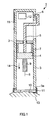
- conventional blood test apparatus 1 which uses a needle as a puncturing means, includes: housing 2 that forms a chassis; cylindrical body 3 having opening at one side included in housing 2; plunger 4 that moves back and forth inside cylindrical body 3; handle 5, one end of which is connected to plunger 4; latch part 6 that latches handle 5 at housing 2; spring 7 that urges handle 5 toward opening part 3a of cylindrical body 3; lancet 9 which has one end held by plunger 4 and the other end attached with blood collection needle (hereinafter "needle") 8; holding part 11 that holds blood sensor 10 on the side of opening part 3a; and electrical circuit section 12 to which the output of sensor 10 is connected.
- needle blood collection needle
- Blood sensor 10 and needle 8 are replaced to eliminate the influence of blood which has already been examined.
- holding part 11 is removed and then sensor 10 after use is removed.
- new blood sensor 10 is attached to holding part 11. Then, holding part 11 is attached to opening part 3a again. If the neighborhood of holding part 11 is stained with, for example, blood, it is cleaned.
- blood test apparatus 1 is abutted on the skin of the patient, and the latching of latch part 6 is released. Then, handle 5, urged by spring 7, is propelled in the direction of arrow 14. By this release of latching of handle 5, needle 8, connected to this handle 5 via plunger 4 and lancet 9, is propelled at the same time. Needle 8 breaks through sensor 10 and punctures skin 13.
- the outflowing blood is guided into inside blood sensor 10.
- the blood guided into blood sensor 10 causes chemical change in sensor 10 according to the blood sugar level of the patient.
- the current produced by the chemical change is led to electrical circuit section 12, and the blood sugar level is measured.
- the calculated blood sugar level is displayed on display section 15. Based on the calculated blood sugar level, for example, basic data showing the amount of insulin to administer to the patient is provided.
- US 2002/0173732 A1 describes a blood withdrawal and analysis system including a disposable fluid displacement device mounted within a portal housing, which has sensor elements mounted on either sides of a removable slide included in the disposable fluid device.
- a logic processing unit controls the pulse rate of the laser and performs the necessary analysis of the blood.
- a laser apparatus consumes a large amount of power, and, for example, when a battery is used for the power supply, the battery capacity may be used up after several times of puncturing.
- the battery for the power supply which is used up, no longer enables puncturing, much less the operation of the measuring circuit for examining blood.
- the blood test apparatus is an apparatus that influences life of the patient (for example, diabetes patient) who is the user, and should be designed so that, even if the puncturing means does not operate, at least blood test (for example, measurement of blood sugar level) can be performed, because puncturing can be performed using a means other than laser light.
- the first example for understanding the present invention relates to the following blood test apparatus.
- the blood test apparatus of [3] and [4] may further include a display section that displays a test result of the blood test.
- the second aspect of the present invention relates to the following method of controlling the blood test apparatus.
- the blood test apparatus of the present invention can prevent a situation wherein test cannot be performed due to power shortage of the power supply although laser light is used as the puncturing means. Particularly, even if the battery with a limited capacity is used for the power supply, the user can perform a test stably. Therefore, the present invention is particularly applicable to a portable blood test apparatus.
- the present invention provides a blood test apparatus using laser light as a means for puncturing skin and can bring skin in a predetermined position by sucking force.
- the focal point of laser light is set correctly with respect to the skin brought in the predetermined position.
- the skin is placed in close contact with the blood sensor by sucking force, so that the blood flowing out from the skin punctured with laser light can be led inside the blood sensor (detecting section) in a reliable manner.
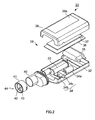
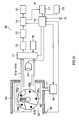
- FIG.2 is an exploded assembly perspective view showing the overall configuration of a first example of the blood test apparatus of the present invention.
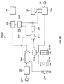
- the interior of lower case 32 of blood test apparatus 31 shown in FIG.2 accommodates components including: laser emitting apparatus 33; negative pressure means 34 which is configured with suction pump (negative pressure pump) 34a, pump valve unit 34b and vent switch 34c; battery 35 which supplies power to electrical components; electrical circuit section 36 which is mounted on these components; and display section 37 which is mounted on electrical circuit section 36, and, for example, made of liquid crystal.
- Apparatus body 39 is configured so that upper case 38 covers lower case 32 that accommodates the components.
- Transparent display window 38a is provided in upper case 38 in the position corresponding to display section 37.
- Apparatus body 39 is connected to blood sensor unit 44 via adapter 40.
- One end of adapter 40 is a cylinder-shaped body, and blood sensor unit 44 is inserted removably into adapter 40.
- Blood sensor unit 44 is configured with holder 41 and blood sensor 42 attached inside holder 41.
- Window 43 provided in the center of blood sensor unit 44 is a part for allowing laser light from the laser emitting hole of laser emitting apparatus 33 to pass through.
- Window 43 may be a hole or a member formed with a material that allows laser light to pass through.
- FIG.3 is an exploded assembly perspective view showing the overall configuration of a second example of the blood test apparatus of the present invention.
- FIG.4 is its side view.
- Blood test apparatus 31a shown in FIG.3 and FIG.4 is different from blood test apparatus 31 shown in FIG.2 in that the apparatus has a manual pump that enables manual suction as a negative pressure pump constituting negative pressure means 140. The difference will be described below.
- Blood test apparatus 31a has negative pressure means 140 including manual pump (negative pressure pump) 141 and manual pump knob 142 that drives manual pump 141 manually. Vent switch 144 releases the negative pressure created in pump valve unit 143 to the atmosphere.
- Manual pump knob 142 has the shape of an arch, and its one end is made spindle 142a and the other end is made operating part 142b (see FIG.4 ). Manual pump knob 142 can rotate about spindle 142a. Operating part 142b transmits power to manual pump 141. The patient holds manual pump knob 142 with apparatus body 39 and can move operating part 142b up and down. By this up-and-down motion manual pump 141 starts to create a negative pressure.
- the exterior of blood sensor unit 44 is preferably formed with a transparent material so that the interior of negative pressure chamber 60 (see FIG.16 , for example) can be seen.
- the whole of the exterior of blood sensor unit 44 may be formed with a transparent material or only the tip 41h side (the negative pressure chamber 60 side) of blood sensor unit 44 may be formed with a transparent material.
- Grip part 142c of manual pump knob 142 may have finger-shaped pattern with indentations and projections to prevent the fingers from slipping.
- the first aspect of the laser emitting apparatus (including a lens)
- the blood test apparatus of the present invention uses laser light as a means for puncturing skin.
- the laser light is absorbed by the OH group of water of the skin, which increases heat instantaneously and evaporates the water.
- the surrounding cells also evaporate at this time, to form a hole in the skin.
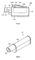
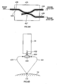
- FIG.5 is an exterior perspective view of laser emitting apparatus 33 accommodated in the blood test apparatus.
- FIG.6A and FIG.6B are cross-sectional views of laser emitting apparatus 33.
- laser crystal 33d is arranged in the internal part surrounded by the walls where partially reflecting mirror 33f and total reflection mirror 33g are provided.
- laser crystal 33d has partially reflecting mirror 33f and total reflection mirror 33g on both sides and is attached on the outer wall and the inner wall (partition) of cylindrical body 33b. That is, in FIG.6B , laser crystal (laser rod) 33d is long and extends beyond the inner wall (partition).
- Laser emitting apparatus 33 is configured with oscillation tube 33a and cylindrical body 33b connected to front side of oscillation tube 33a.
- Laser emitting port 33c is provided in the center of the front side of cylindrical body 33b.
- Oscillation tube 33a accommodates Er:YAG (yttrium aluminum garnet) doped with erbium, or Ho:YAG laser crystal 33d doped with Holmium, and excitation light source 33e which includes a xenon flashlamp.
- Partially reflecting mirror 33f is attached at one end of oscillation tube 33a (particularly, see FIG.6A ).
- the transmittance of partially reflecting mirror 33f may be approximately 1 to 10%.
- Total reflection mirror 33g with a transmittance of 99 to 100% is attached to the other end of oscillation tube 33a (see FIG.6A and FIG.6B ).
- films having the same properties may be placed on the end face of the laser crystal by sputtering.
- Convex lens (focus lens) 33h is mounted inside cylindrical body 33b. Convex lens 33h focuses laser light near the surface of blood sensor 42 (described in detail later). Total reflection mirror 33g, YAG laser crystal 33d, partially reflecting mirror 33f, lens 33h and laser emitting hole 33c are arranged in this order.
- the excitation light emitted from excitation light source 33e penetrates to Er:YAG laser crystal 33d and creates a high energy state by exciting Er (erbium) ion.
- Er:YAG laser crystal 33d becomes a reverse distribution state, and laser light resonates and is amplified in YAG laser crystal 33d while reflecting between total reflection mirror 33g and partially reflecting mirror 33f.
- Ho Ho (Holmium).
- Part of the amplified laser light passes through partially reflecting mirror 33f by stimulated emission.
- the laser light passing through partially reflecting mirror 33f passes through lens 33h and is emitted from laser emitting port 33c. As described later, the laser light emitted from laser emitting port 33c punctures (irradiates) the skin.
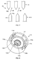
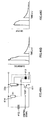
- FIG.7 shows another example of the laser emitting apparatus.
- Laser emitting apparatus 189 shown in FIG.7 irradiates two kinds of laser crystals with excitation light using one flashlamp 185 as an excitation light source. At this time, laser light is outputted from each laser crystal. Use of two kinds of crystals enables output of laser lights of different intensities and wavelengths.
- laser emitting apparatus 189 includes: chassis 188 which has a shape of two overlapping cylindrical bodies having an elliptical cross section; flashlamp 185 for exciting laser light, which is arranged in the central position of chassis 188; and first crystal 186 and second crystal 187 for oscillating laser light, which are arranged at the both sides of flashlamp 185.
- chassis 188 which has a shape of two overlapping cylindrical bodies having an elliptical cross section
- flashlamp 185 for exciting laser light which is arranged in the central position of chassis 188
- first crystal 186 and second crystal 187 for oscillating laser light, which are arranged at the both sides of flashlamp 185.
- Chassis 188 has a shape of two overlapping ellipses. Each ellipse has two focal points and shares one focal point with the other ellipse, so that there are three focal points.
- first crystal 186 is arranged in one of the focal points
- second crystal 187 is
- the intensity of laser light output is proportional to the light emitting intensity of flashlamp 185 and is also proportional to the volumes of crystal 186 and crystal 187. Therefore, by arranging two crystals of the same diameter and different lengths, it is possible to obtain two laser lights of different intensities using one flashlamp 185.
- Er:YAG and Nd:YAG are preferably emitted in this order with a little time lag.
- laser emitting apparatus 189 By using laser emitting apparatus 189, it is possible to use the wavelength of the laser light selectively. Further, by irradiating the same position with two types of laser lights using an optical system, it is possible to improve output intensity.
- the blood test apparatus of the present invention uses a laser emitting apparatus as a means for puncturing the skin of the patient that can perform puncturing without contact with the skin, so that the puncturing needle required in the conventional blood test apparatus, is no longer required. Further, the blood test apparatus uses a puncturing means that does not contact with the skin of the patient, and so is sanitary. Still further, although it is necessary to replace the puncturing needle every test by the conventional blood test apparatus, the test by the blood test apparatus of the present invention does not require this replacement. Further, the blood test apparatus of the present invention does not require moving component for moving a needle required for puncturing with a needle, which reduces troubles. Further, the number of components required in the blood test apparatus of the present invention is reduced, so that components control becomes simple. Further, by providing a transparent waterproof wall on the front face of laser emitting port 33c, it is possible to wash the whole of the blood test apparatus.
- the blood test apparatus of the present invention has a blood sensor for taking in the blood flowing out from the punctured skin and examining the blood components.
- FIG.8 is a cross-sectional view of the first example of the blood sensor.
- Blood sensor 42 shown in FIG.8 has an outer shape of a round or polygon.
- Base plate 45 constituting blood sensor 42 has: substrate 46; spacer 47 stacked on the upper face of substrate 46; and cover 48 stacked on the upper face of spacer 47.
- Blood storing part 49 is provided near the center of base plate 45. Storing part 49 is formed so as to communicate with hole 46a provided in substrate 46 and hole 47a provided in spacer 47. Storing part 49 opens downward to collect blood from the skin.
- the volume of storing part 49 is, for example, 0.904 ⁇ L, but is by no means particularly limited.
- One end of supply channel 50 is connected to storing part 49.
- the volume of supply channel 50 is, for example, 0.144 ⁇ L, but is by no means particularly limited.
- Detecting section 51 is arranged inside supply channel 50. Blood stored in storing part 49 flows into supply channel 50 by capillary action and is led to detecting section 51. The other end of supply channel 50 is connected to air hole 52.
- the diameter of air hole 52 may be approximately 50 ⁇ m to 250 ⁇ m. By making the diameter of air hole 52 small, blood is prevented from flowing out through air hole 52 excessively. Further, in a state where storing part 49 is in close contact with the skin, air hole 52 operates as a negative pressure path through which a negative pressure is created in storing part 49.
- Reagent 53 mounted on detecting section 51 may be prepared as appropriate according to a test target.
- reagent 53 is prepared by dropping a reagent solution on detecting section 51 arranged on substrate 46, and drying the reagent solution, wherein the reagent is prepared by adding and dissolving an enzyme (PQQ-GDH) of 0.1 to 5.0 U/sensor, potassium ferricyanide (10 to 200 mM), maltitol (1 to 50 mM) and taurine (20 to 200 mM) to a 0.01 to 2.0 wt% aqueous solution of CMC.
- PQQ-GDH an enzyme
- Storing part 49 of blood sensor 42 is sealed with face 49a (hereinafter "ceiling farce”).
- the emitted laser light preferably transmits through ceiling face 49a, so that blood flowing out from the skin punctured with laser light does not flow out from ceiling face 49a.
- cover 48 may be formed with the material that allows laser light to transmit (for example, glass or plastic such as polyimide).
- the laser light may perforate ceiling face 49a.
- substrate 46, spacer 47 and cover 48 may be formed with the same material.
- the hole formed in ceiling face 49a can serve as air hole 52, as well as a negative pressure path through which the negative pressure means creates a negative pressure in storing part 49.
- FIG. 9 is a cross-sectional view of the second example of the blood sensor. While ceiling face 49a of storing part 49 of blood sensor 42 shown in FIG.8 is sealed, the ceiling face of storing part 49 of blood sensor 103 shown in FIG.9 is open.
- Hole 103b is formed in cover 48 of blood sensor 103.
- the diameter of hole 103b (for example, 1.0 mm) is smaller than the diameter of storing part 49 (for example, 2.0 mm), and is greater than the diameter of air hole 52 (50 ⁇ m to 250 ⁇ m).
- Hole 103b is preferably located in the center of the ceiling face of storing part 49. Laser light passes through hole 103b and punctures the skin. By providing hole 103b, it is possible to prevent laser light from declining. It is thereby possible to reduce the energy of laser light to be emitted.
- Hole 103b and air hole 52 can serve as a negative pressure path through which negative pressure means 34 and 140 create a negative pressure in storing part 49.
- the surface tension of blood 16 generated inside hole 103b prevents blood 16 collected by puncturing the skin from overflowing out from the upper face of the cover. Blood 16 spreads through inside storing part 49. Therefore, it is possible to collect an adequate amount of blood 16. Blood 16 that fills storing part 49 flows into supply channel 50 by capillary action.
- hole 103b is water-repellent, blood 16 is less likely to overflow through hole 103b. Therefore, the interior of the blood test apparatus is not contaminated with blood.
- PET Polyethylene terephthalate
- Laser light passes through hole 103b of storing part 49, and laser light may pass through the center of hole 103b or pass through a position out of the center of hole 103b. For example, by making laser light pass through a position farther from supply channel 50 than the center of hole 103b, blood 16 flowing out from skin 13 fills the interior of storing part 49 completely, and then flows into supply channel 50, so that it is possible to realize accurate measurement.
- Hole 103b is formed in advance in the ceiling face of storing part 49 of blood sensor 103. In this way, hole 103b is formed in advance, so that it is not necessary to adjust the axis of the laser light to the part to be perforated. Therefore, blood sensor 103 is easily attached to blood sensor unit 44. Hole 103b may be made small, approximately 0.05 to 0.25 mm, and preferably prevents blood 16 from flowing out through the puncturing hole.
- the blood sensors in the blood test apparatus of the present invention preferably has storing part 49 and supply channel 50.
- the inner wall surface of supply channel 50 is preferably hydrophilic so that blood is transferred smoothly to supply channel 50 where detecting section 51 is arranged. Further, the inner wall surface of supply channel 50 is preferably more hydrophilic than the inner wall surface of storing part 49 so that blood stored in storing part 49 is supplied to supply channel 50 smoothly.
- the blood sensor in the blood test apparatus of the present invention has cover 48, and cover 48 forms the ceiling face of storing part 49.
- Upper faces 48a and 103a (faces irradiated with laser light) of cover 48 are preferably water-repellent. More particularly, upper faces 48a and 103a of cover 48 are preferably more water-repellent than the inner wall surface of storing part 49, so that blood stored in storing part 49 is prevented from flowing out through the hole (the hole perforated with laser light or hole 103b) formed on cover 48.
- the third example of the blood sensor is the third example of the blood sensor
- the wetness of skin 13 of the patient varies depending on the environment.
- skin 13 to be punctured with laser light preferably has a certain level of moisture content. Therefore, in order to perform measurement in a stable, a certain level of wetness is preferably maintained by giving a certain level of moisture content to skin 13 by moistening the neighborhood of skin 13 before puncturing with laser light.
- FIG.11 shows blood sensor 42a provided with water storing part 195 that stores water, on the lower face side that comes into contact with on skin 13, of blood sensor 42 (see FIG.8 in detail).
- water storing part 195 of blood sensor 42a shown in FIG.11 breaks to splash a certain amount of water on skin 13 and moisten the skin which is lifted by negative pressure means 34 and 140 before laser light is emitted.
- Water storing part 195 may be, for example, a container which contains water and which is made of a plastic material such as PET, or a soft bag, a sponge or a spongy member that is soaked with water.
- Water storing part 195 is preferably not arranged in transmission part 196 through which laser light passes, because the intensity of the laser light is reduced by water.
- FIG.12 is a perspective plan view of blood sensor 42.
- detection electrodes 54 to 57 are arranged, and in order from storing part 49 toward air hole 52, detection electrode 57 (Hct (hematocrit) electrode), detection electrode 56 (counter electrode), detection electrode 54 (active electrode), detection electrode 56 (counter electrode) and detection electrode 55 (sensing electrode) are arranged.
- Detection electrodes 54 to 56 are arranged in detecting section 51.
- Detection electrodes 54 to 57 are connected to connection electrodes 54a to 57a, respectively.
- Connection electrodes 54a to 57a extend up to the outer periphery of substrate 46.
- Contact parts 54b to 57b are provided in connection electrodes 54a to 57a.
- contact part 56c is also provided in addition to contact part 56b, so that two contact parts are provided.
- Reference electrode 56d may be provided in connection electrode (54a, 55a and 57a) other than connection electrode 56a.
- Contact parts 54b to 57b and contact part 56c are arranged near the outer periphery of sensor 42 at virtually regular intervals.
- connection electrodes 56a, 57a, 54a and 55a are specified clockwise.
- blood sensor 42 has reference electrode 56d, so that it is possible to specify the connection electrodes. Therefore, even if the contact parts (54b to 57b and 56c) are connected casually to the five connectors arranged in apparatus body 39, it is possible to specify the connection electrodes and perform measurement. Accordingly, blood sensor 42 (or blood sensor unit 44 including blood sensor 42) can be made in a symmetrical shape so that blood sensor 42 can be attached to apparatus body 39 casually in a very simple manner.
- Aligning concave part 46c may be provided on the outer periphery of substrate 46. On the outer peripheries of spacer 47 and cover 48, aligning concave parts 47c and 48c are provided so as to correspond to aligning concave part 46c. By using aligning concave parts 46c to 48c, blood sensor 42 can be attached to blood sensor unit 44 so as to meet a predetermined alignment of blood sensor unit 44.
- Connection electrode 56a and reference electrode 56d are connected via laser-machined pattern 56e. By changing the width of pattern 56e, the resistance value between contact part 56b and reference contact part 56c can be changed.
- Reference electrode 56d serves as a reference for specifying the positions of connection electrodes 54a to 57a.
- Reference electrode 56d can be utilized to identify the product specifications of blood sensor 101.
- the blood test apparatus is set so that calibration curve 1 is used when the resistance value of pattern 56e is 200 to 1000 ohms, calibration curve 2 is used when the resistance value is 1000 to 2000 ohms, and calibration curve 3 is used when the resistance value is 2000 to 3000 ohms, the calibration curve of the sensor is recognized automatically, and the blood sugar level is measured using an appropriate calibration curve.
- the reference electrode can be used to identify various product specifications, in addition to use in automatic recognition of the calibration curve.
- the reference electrode can be used to identify the users the product is shipped to, for example, to identify whether the product has the specifications for company A or the specifications for company B.
- pattern 56e By forming pattern 56e with an inductance having arbitrary property, connecting the inductance to a resonator constituting an oscillator and changing the oscillation frequency according to this inductance property, various information can be provided.
- connection electrodes 54a to 57a can be specified. Therefore, when blood sensor unit 44 is attached, the attaching direction does not have to be adjusted visually, so that it is possible to attach blood sensor unit 44 in a simple manner.
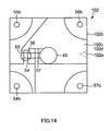
- FIG. 14 is a transparent plan view of a square-shaped blood sensor.
- the outer shape of blood sensor 102 shown in FIG.14 is a square, the outer shape may be a polygonal such as a hexagon and octagon.
- aligning concave part 102a for aligning blood sensor unit 44 may be provided in one of the four sides of blood sensor 102, in such a case blood sensor 102 has an asymmetrical shape.
- Concave part 102a serves as the reference when blood sensor 102 is attached to blood sensor unit 44.
- detection electrodes 54 to 57 can be specified even if reference electrode 56d is not provided.
- FIG.15 is an exploded plan view of blood sensor 42.
- FIG.15A is a plan view of cover 48
- FIG.15B is a plan view of spacer 47
- FIG.15C is a plan view of substrate 46.
- FIG.15C is a plan view of round substrate 46 constituting blood sensor 42.
- the diameter of substrate 46 may be approximately 8.0 mm.
- the material of substrate 46 is resin such as polyethylene terephthalate (PET), and its thickness may be 0.075 to 0.250 mm (for example, 0.188 mm).
- detection electrodes 54 to 57, and connection electrodes 54a to 57a derived from detection electrodes 54 to 57, respectively, are formed in an integrated manner. These detection electrodes and connection electrodes may be formed by applying laser processing to a conductive layer formed with the sputtering method or the vapor deposition method.
- the material of the conductive layer can be gold, platinum and palladium as materials.
- the diameter of hole 46a provided near the center of substrate 46 may be approximately 2.0 mm.
- the wall surface of hole 46a is less hydrophilic than supply channel 50 or is less water-repellent than upper face 48a of cover 48.
- Hole 46a is preferably formed by punching press substrate 46 from the side of detection electrodes 54 to 57, using a convex mold, because it is less likely to damage detection electrodes 54 to 57. Further, even if a burr is produced in hole 46a by this punching, the burr is oriented downward (toward the skin). Therefore, blood 16 is prevented from flowing out from storing part 49.
- Concave part 46c for aligning provided on the outer periphery of substrate 46 engages with a aligning convex part formed in cylindrical body 41e of blood sensor unit 44 (see FIG.16 ). The alignment where blood sensor 42 is attached to blood sensor unit 44 is thereby determined.
- hole 47a provided near the center of spacer 47 is 2.0 mm, and hole 47a is provided in the position corresponding to hole 46a provided in substrate 46.
- the wall surface of hole 47a is less hydrophilic than supply channel 50 or is less water-repellent than upper face 48a of cover 48.
- Storing part 49 is constituted with hole 46a and hole 47a.
- Concave part 47c for aligning provided on the outer periphery of spacer 47 is formed in the position meeting concave part 46c for aligning provided in substrate 46.
- FIG.15A is a plan view of cover 48.
- the diameter of cover 48 may be approximately 5.2 mm.
- the thickness of cover 48 may be approximately 0.050 to 0.125 mm (for example, 0.075 mm).
- Cover 48 can be made of a material that does not absorb laser light. Examples of the material of cover 48 include glass and plastic such as polyimide. When laser light is not absorbed in cover 48, the laser light can pass through ceiling face 49a of storing part 49 to puncture the skin. The laser light does not perforate ceiling face 49a, and so blood 16 does not flow out through the hole, and blood 16 does not flow into apparatus body 39.
- Air hole 52 is provided to meet the tip part of supply channel 50.
- the diameter of air hole 52 is 50 ⁇ m.
- Upper face 48a (see FIG.8 ) of cover 48 that forms the upper face of substrate 45 is preferably subjected to water-repellency treatment.
- the ceiling face of supply channel 50 is preferably subjected to hydrophilicity treatment.
- ceiling face 49a of storing part 49 is subjected to weaker hydrophilicity treatment than supply channel 50 or is subjected to weaker water-repellency treatment than upper face 48a of cover 48.
- the hydrophilicity or water-repellency of the components of blood sensor 42 can be adjusted as follows. Upper face 48a of cover 48 is subjected to water-repellency treatment in advance. On the other hand, the overall lower face of cover 48 is subjected to hydrophilicity treatment. The lower face of cover 48 includes the ceiling face of supply channel 50. Next, substrate 46, spacer 47 and cover 48 are stacked. After substrate 46, spacer 47 and cover 48 are stacked, the hydrophilic material of ceiling face 49e may be dissolved and removed by radiating short-wavelength UV from the opening of storing part 49.
- the ratio of the volume of storing part 49 (0. 904 ⁇ L) and the volume of supply channel 50 (0.144 ⁇ L) may be approximately 6:1, but the ratio is not particularly limited. By this means, test does not become incorrect, even when the amount of blood 16 is small. Further, the volume of storing part 49 is not too large with respect to the volume of supply channel 50 required, so that a large amount of blood 16 does not flow into supply channel 50 and does not wash away reagent 53 (see FIG.8 ). Therefore, the rate of flow of blood 16 becomes constant, which does not generate variation in concentration of reagent 53, so that it is possible to examine blood 16 accurately.
- the blood sensor unit The blood sensor unit
- the blood sensor in the blood test apparatus of the present invention may be included in the blood sensor unit.
- the blood sensor unit can be attached to and removed from the apparatus body and is a replaceable member.
- FIG.16 is a cross-sectional view of blood sensor unit 44 and the neighborhood of blood sensor unit 44.
- the cross section of blood sensor unit 44 is configured in the shape of "H” by cylinder-shaped holder 41 that opens upward and downward, and attaching part 41b that is provided so as to seal the interior of holder 41.
- the material of holder 41 is preferably resin that is applicable to injection molding, including ABS resin, AS resin and thermoplastic resin such as polyethylene, polypropylene, polyvinyl chloride and polyethylene terephthalate, or thermosetting resin such as phenol resin, epoxide resin and silicon resin.
- window 43 is preferably provided so as to correspond to storing part 49.
- the area of the opening part of window 43 is preferably larger than the area of the opening part of storing part 49.
- negative pressure path 41c is provided that penetrates the upper side and the lower side of attaching part 41b. Negative pressure path 41c may be provided, for example, between the outer periphery of blood sensor 42 and the inner periphery of holder 41.
- Cylindrical body 41d located below attaching part 41b forms negative pressure chamber 60 between skin 13 and cylindrical body 41d. Further, the inner wall of cylindrical body 41e located above attaching part 41b of blood sensor unit 44 is latched outside adapter 40.
- Connector 61 is provided inside adapter 40.
- Connector 61 includes a plurality of (for example, five) individual connectors 61a to 61e.
- Connector 61a to 61e contact with contact parts 54b to 57b and 56c of blood sensor 42, respectively. Signals of connectors 61a to 61e are led to electrical circuit section 36.
- First skin contact sensor 62 provided at tip 41h of cylindrical body 41d detects skin 13 when blood sensor unit 44 comes into contact with skin 13.
- First skin contact sensor 62 also connects to connection part 62c provided in adapter 40 via conductor 62a arranged inside holder 41, and further connects to conductor 62b at the adapter 40 side. Conductor 62b is led to electrical circuit section 36.
- a plurality of (for example, two) first skin contact sensors 62 made of conductors are preferably provided in different parts in tip 41h of cylindrical body 41d (in FIG.16 , two first skin contact sensors 62 are provided symmetrically with respect to the center of cylindrical body 41d).
- first skin contact sensor 62 By measuring the resistance value between two conductors of first skin contact sensor 62, skin 13 is detected when blood sensor unit 44 comes into contact with skin 13. Therefore, it is possible to detect skin 13 when the tip of blood sensor unit 44 comes into contact with skin 13 completely without space.
- Laser light is preferably not allowed to emit unless first skin contact sensor 62 detects a contact with the skin.
- First skin contact sensor 62 may be a mechanical micro switch or a reflection optical switch.
- a guide part for attaching blood sensor unit 44 in a simple manner may be provided in cylindrical body 41d and adapter 40 of blood sensor unit 44.
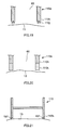
- FIG.17 is an exploded elevation view of the primary part of guide part 63 that guides insertion of blood sensor unit 44 into adapter 40.
- Convex part 41f is formed inside cylindrical body 41d, and convex part 40f is formed outside adapter 40.
- Tip part 41g and tip part 40g which are the tips of convex part 41f and convex part 40f, respectively, are made sharp.
- Tip part 41g and tip part 40g face each other.
- Convex part 40f and its tip part 40g, and convex part 41f and its tip part 41g, constitute guide part 63.
- blood sensor unit 44 When blood sensor unit 44 is inserted into adapter 40, even when the relative alignment between blood sensor unit 44 and adapter 40 is out of predetermined alignment, blood sensor unit 44 is inserted along guide part 63 while correcting the course (see arrow 64). As a result, connectors 61a to 61e provided in adapter 40 are sure to contact with one of contact parts 54b to 57b and 56c provided in sensor 42. Therefore, blood sensor unit 44 can be inserted without taking into account the rotation angle with respect to the axis of the insertion direction, so that blood sensor unit 44 can be attached in a simple manner.
- FIG.18 is a diagrammatic perspective view of the blood sensor unit.
- Blood sensor unit 110 shown in FIG.18 may have the same structure as blood sensor unit 44 unless described otherwise.
- Blood sensor unit 110 has the shape of a cylinder, and its cross section has the shape of "H.”
- Five connectors 111 that transmit signals of the contact part of the blood sensor (one of blood sensors 42, 101, 102 and 103) to electrical circuit section 36 may be provided inside holder 110a of blood sensor unit 110 (in the case of blood sensor 102, four connectors may be provided).
- Connector 111 connects to adapter 40 at an upper end of holder 110a and is led to electrical circuit section 36 via this adapter 40.
- Connector 111 may be provided in the adapter and may be connected with the contact part of the blood sensor of blood sensor unit 110.
- Air hole 110d provided in attaching part 110b is provided in the position meeting air hole 52 of blood sensor 42. Air hole 110d is provided so that blood 16 runs into supply channel 50 of blood sensor 42 or create a negative pressure in storing part 49.
- FIG.19 is a cross-sectional view showing the primary part of one configuration example of neighborhood of lower end 110h of holder 110a.
- An end part of lower end 110h comes into contact with skin 13 of the patient and forms negative pressure chamber 60.
- Lower end 110h needs to closely contact with skin 13. Therefore, lower end 110h may be formed with two concentric lines 110j which are made sharp at an acute angle. Since line 110j comes into contact with skin 13 reliably by line contact, negative pressure chamber 60 is kept sealed.
- the number of lines 110j does not have to be two, and there may be one or a plurality of lines 110j.
- FIG.20 is a cross-sectional view showing the primary part of another configuration example near lower end 110h of holder 110a.
- Concentric contacting part 110k made of elasticity such as rubber, silicon, urethane and a sponge, is formed in lower end 110h. Therefore, contacting part 110k can come into close contact with skin 13 by its elasticity, and negative pressure chamber 60 is kept sealed.
- the contact surface of contacting part 110k is preferably a flat to increase the area where contacting part 110k comes into contact with skin 13.
- contacting part 110k By forming contacting part 110k with an absorbing member, such as a sponge, that has absorbency, it is possible to wipe off over-sampled blood 16 flowing out by puncturing after measurement. Therefore, it is not necessary to prepare wiping paper. Further, if an antiseptic is applied to the absorbing member, the absorbing member becomes sanitary.
- an absorbing member such as a sponge
- the blood test apparatus of the present invention has a negative pressure means, the negative pressure means create a negative pressure inside blood sensor unit 110.
- groove 110f may be formed in attaching part 110b of blood sensor unit 110. Groove 110f extends to window 110e formed near the center of attaching part 110b, from the outer periphery side of attaching part 110b of holder 110a.
- a negative pressure is created, a negative pressure is also created in groove 110f, and blood sensor 42 is in close contact with attaching part 110b.
- Connector 111 contacts with blood sensor 42 in contact surface 111a.
- Connector 111 is integrated with holder 110a and formed so as to cut into part of attaching part 110b.
- first skin contact sensor 62 may be provided in lower end 110h of holder 110a.
- the lower space forms negative pressure chamber 60.
- First skin contact sensor 62 is provided in lower end 120h of holder 120a.
- second skin contact sensor 120m is provided in the lower face of attaching part 120b (not shown).
- blood sensor 42 By attaching blood sensor 42 on the upper face of attaching part 120b, it is possible to increase the contact pressure between connector 61 and the contact part (54b to 57b and 56c) of blood sensor 42. Further, it is possible to attach blood sensor 42 to attaching part 120b in a simple manner.
- negative pressure path 120c On creating a negative pressure on skin 13, it is possible to create a negative pressure in the space on the side of skin 13 via this negative pressure path 120c. Further, when a negative pressure is released to the atmosphere, air flows into space on the side of apparatus body 39 quickly via negative pressure path 120c. Therefore, it is possible to prevent blood led in blood sensor 42 from splashing to apparatus body 39.
- Groove 120f may be formed on the upper side of attaching part 120b as a negative pressure path. Groove 120f extends from the outer periphery of attaching part 120b of holder 120a to window 120e formed near the center of attaching part 120b. Providing groove 120f makes it unnecessary to provide a hole (negative pressure path 120c) which penetrates attaching part 120b.
- the diameter of opening part 130e of negative pressure chamber 60 formed on the lower side of attaching part 130b is preferably 2 to 20 mm, more preferably, 3 to 10 mm, and, even more preferably, 5 to 7 mm, so that a negative pressure is created on the skin to be punctured more efficiently. Further, by making the outer shape of lower end 130d smaller than the outer shape of upper end 130c, it is possible to stack a plurality of blood sensor units 130 vertically and accommodate blood sensor units 130 efficiently. Generally, blood sensor 42 needs to have a certain size, and so the outer shape of upper end 130c is difficult to be made smaller.
- FIG.25 is a plan view of blood sensor unit 130.
- Two convex parts 130f that fit concave parts 46c and 47c (see FIG.15 ) for aligning blood sensor 42 are formed in holder 130a of blood sensor unit 130 (at an angle of approximately 120 degrees).
- the alignment where blood sensor 42 is arranged inblood sensor unit 130 is determined by convex part 130f of holder 130a and aligning concave part 46c of blood sensor 42.
- Blood sensor unit 130 where blood sensor 42 is arranged adequately is attached to adapter 40 in a predetermined alignment by guide part 63 (see FIG.17 ). In this way, signals of detection electrodes 54 to 57 of blood sensor 42 are transmitted to electrical circuit section 36.
- the blood test apparatus of the present invention uses laser light as a puncturing means, and, the laser emitting apparatus is accommodated in the apparatus body (see FIG.2 , for example).
- the emitted laser light is focused by a focus lens and emitted to skin.
- laser light is preferably focused near the surface of the blood sensor. As described above, skin to be punctured is sucked in by the negative pressure means and is placed in close contact with the blood sensor, so that the laser light focused near the surface of the blood sensor can puncture the skin effectively.
- the focal point of the laser light may be at the surface of the blood sensor or may be closer to the skin than the surface of the blood sensor or closer to the laser emitting apparatus than the surface of the blood sensor.
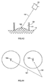
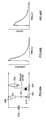
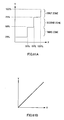
- FIG.26 shows a result of examining using a laser alignment paper (ZAP-IT corporation: Z-48), the relationship between the "burn pattern diameter (mm)" (Y axis) and the “distance (mm) from the laser focus to the target to be punctured (the puncturing target, which in this case is the laser alignment paper)" (X axis).
- the "burn pattern diameter” is the diameter of the hole which is opened when laser light is emitted.
- zone A when the focus is adjusted near the puncturing target, even when the position of the puncturing target shifts somewhat, the burn pattern diameter does not change significantly. Therefore, it is possible to puncture the skin reliably.
- zone B or zone C the burn pattern diameter changes significantly by the shift of the position of the puncturing target.
- the burn pattern diameter change in the same manner, because the focus position of laser light has a relative relationship with the position of the puncturing target. That is, when the position of the puncturing target is fixed, for example, in zone A (when the focus is adjusted near the puncturing target), even if the focal point of laser light shifts somewhat, the burn pattern diameter does not change significantly. Therefore, it is possible to puncture the skin reliably.
- zone B or zone C when the focal point of laser light shifts, the burn pattern diameter changes significantly.
- the focal point of laser light shifts so as to increase the burn pattern diameter, the skin is not punctured, so that safety improves. For example, if the focal point of laser light is adjusted in zone B, unless the position of the puncturing target approaches the position from which the laser light is emitted, up to a predetermined position, the skin is not punctured. That is, unless enough skin is sucked in and lifted by a negative pressure, the skin is not punctured. Further, by adjusting the focal point of the laser light in zone C, when the position of the puncturing target comes closer to the position from which the laser light is emitted, than a predetermined position, the skin is not punctured. That is, when skin is sucked in and lifted more than necessary by a negative pressure, the skin is not punctured.
- the focal point is not preferably adjusted on blood sensor 42, because the film melts and energy of laser light is consumed. Therefore, there is a case where the focal point is preferably adjusted in zone B or zone C.
- the blood test apparatus of the present invention has a negative pressure means, and, the apparatus body accommodates a mechanical suction pump (see 34a in FIG.2 ) or a manual suction pump (see 141 in FIG.3 ) as one component of the negative pressure means.
- the negative pressure means creates a negative pressure in a negative pressure chamber and sucks in and lifts skin, which is the part to be punctured, thereby bringing the skin into close contact with the blood sensor.
- negative pressure means 34 is configured with suction pump 34a, pump valve unit 34b and vent switch 34c (see FIG.2 ).
- Negative pressure means 140 is configured with manual pump 141 and manual pump knob 142, in addition to pump valve unit 143 and vent switch 144 (see FIG.3 ).
- the term “negative pressure means” includes the negative pressure path in addition to the pump (a suction pump or a negative pressure pump) and the valve (a negative pressure valve or an open valve).
- driving the negative pressure means means driving the pump and the valve
- releasing the negative pressure means opening the valve and introducing an outside atmospheric pressure (for example, atmospheric pressure).
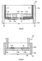
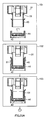
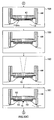
- negative pressure chamber 60 is small, the energy required to create a negative pressure is reduced and the time required for the blood test is also reduced. Therefore, negative pressure chamber 60 (particularly, suction chambers 60a and 60b) inside blood test apparatuses 31 and 31a of the present invention is preferably partitioned by a wall provided closer to blood sensor 42 than laser emitting hole 33c of laser emitting apparatus 33.
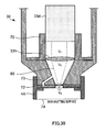
- wall (partition or dividing wall for a negative pressure) 70 that partitions suction chambers 60a and 60b is preferably arranged in the same position as laser emitting hole 33c or in the same position as focus lens 33h (that is, the wall and focus lens 33h are integrated), or focus lens 33h itself may serve as a wall. Examples shown in FIG.27 and FIG.28 show the latter case.
- the shape of the suction chamber may be a conically-shaped (see suction chamber 60b in FIG.28 ).
- Apparatus body 39 has negative pressure path 71 that communicates with suction chambers 60a and 60b, and this negative pressure path 71 is connected to the suction port of pump 34a.
- storing part 49, supply channel 50 and air hole 52 which also function as negative pressure path 72, are provided inside blood sensor 42.
- Suction chambers 60a and 60b also communicate with this negative pressure path 72 in blood sensor 42.
- tiny negative pressure path 73 that connects suction chamber 60b and air hole 52 is further provided in apparatus body 39.
- Negative pressure paths 72 and 73 are micro-channels, having approximately zero volume.
- FIG.31 is a block diagram of electrical circuit section 36.
- 54b to 57b and 56c are contact parts provided in blood sensor 42.
- Contact parts 54b to 57b and 56c are connected to switch circuit 71 via connectors 61a to 61e.
- the output of switch circuit 71 is connected to the input of current/voltage converter 72.
- the output of current/voltage converter 72 is connected to the input of calculating section 74 via analogue/digital converter (hereinafter "A/D converter") 73.
- A/D converter analogue/digital converter
- the output of calculating section 74 is connected to display section 37 formed with liquid crystal.
- reference voltage supply 78 is connected to switch circuit 71.
- Reference voltage supply 78 may be a ground potential.
- controlling section 76 is connected to a control terminal of switch circuit 71, calculating section 74, puncture button 75, transmitting section 77, timer 79, laser emitting apparatus 33, negative pressure means 34 (particularly, suction pump 34a) and first skin contact sensor 62, and also connected to a warning means (not shown) and second skin contact sensor 110m (see FIG.22 ). Further, the output of calculating section 74 is also connected to the input of transmitting section 77.
- the suction port of negative pressure means 34 (particularly, pump valve unit 34b) is led inside negative pressure chamber 60 and blood sensor unit 44 via negative pressure path 71.
- glucose which is a blood component
- the glucose content is measured by, first, switching switch circuit 71 by the command from controlling section 76 and connecting detection electrode 54, which serves as the active electrode for measuring the glucose content, to current/voltage converter 72 via connectors 61. Further, detection electrode 56, which serves as the counter electrode for measuring the glucose content, is connected to reference voltage supply 78 via connectors 61.
- Hct hematocrit
- switch circuit 71 is switched.
- Detection electrode 57 which serves as an active electrode for measuring the Hct level, is connected to current/voltage converter 72 via connectors 61.
- detection electrode 54 which serves as a counter electrode for measuring the Hct level, is connected to reference voltage supply 78 via connectors 61.
- a certain voltage (2V to 3V) is applied between detection electrode 57 and detection electrode 54.
- the current flowing between detection electrode 57 and detection electrode 54 is converted to a voltage by current/voltage converter 72.
- This voltage value is converted to a digital value by A/D converter 73.
- This digital value is outputted to calculating section 74.
- Calculating section 74 calculates the Hct level based on this digital value.
- the glucose content is corrected with the Hct level.
- the corrected result is displayed on display section 37.
- the blood test apparatus of the present invention has been described using an example of measuring glucose, the blood test apparatus of the present invention is also applicable to measurement of the blood component (such as the lactate level acid and cholesterol) other than glucose.
- the blood component such as the lactate level acid and cholesterol
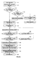
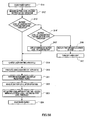
- blood sensor unit 44 is attached to blood test apparatus 31 (step 81).
- blood sensor unit 44 is inserted into adapter 40.
- the tip of adapter 40 abuts on attaching part 41b of blood sensor unit 44.
- Blood sensor unit 44 is latched to adapter 40 by the elasticity of holder 41.
- puncture button 75 is pressed (step 84).
- a signal of puncture button 75 is recognized in electrical circuit section 36.
- electrical circuit section 36 starts laser emitting apparatus 33, laser light is emitted toward skin 13.
- the puncturing voltage of the laser light approximately 300 V, the pain the patient feels is alleviated.
- the Hct level is measured (step 87).
- a voltage is applied between detection electrode 57 as the active electrode and detection electrode 54 as the counter electrode, a current that depends on the Hct level is measured. The Hct level is measured based on this current.
- step 88 the blood components are corrected. That is, the glucose content calculated in step 86 is corrected with the Hct level measured in step 87.. The corrected result is displayed on display section 37.
- blood sensor unit 44 after use is discarded.
- FIG.33 schematically illustrates a flowchart of measuring steps in more detail.
- step 151 shows a state before blood sensor unit 44 is attached to adapter 40 of blood test apparatus 31.
- step 152 shows a state where blood sensor unit 44 is inserted into adapter 40 along guide part 63 (see FIG.7 ).
- Step 153 shows a state where connector 61 is pressed down and contacts with contact parts 54b to 57b and 56c of sensor 42.
- step 154 a main switch of blood test apparatus 31 is turned on. Electrical circuit section 36 detects reference electrode 56d automatically and specifies each of detection electrodes 54 to 57. Display section 37 then displays that preparation for measurement is completed.
- step 155 the end part of blood sensor unit 44 of blood test apparatus 31 is abutted on skin 13.
- apparatus body 39 of blood test apparatus 31 is omitted, and only blood sensor unit 44 is shown.
- step 156 blood test apparatus 31 is abutted on skin 13 of the patient.
- First skin contact sensor 62 detects skin 13 when blood test apparatus 31 comes into contact with skin 13.
- step 157 is started.
- Negative pressure means 34 starts operating and vacuums negative pressure chamber 60 as shown by arrow 157a.
- skin 13 is lifted.
- display section 37 displays start of manual operation, and the patient starts operating manual pump knob 142.
- Second skin contact sensor 110m maybe formed on the reverse side of blood sensor 42 attached on the lower face of blood sensor unit 44 (see FIG.22 ) or formed on the lower face of attaching part 120bwhen blood sensor 42 is attached on the upper face of blood sensor unit 44 (see FIG.23 ). Second skin contact sensor 110m only has to detect a contact between skin 13 and blood sensor 42, and, for example, an optical sensor, a mechanical switch or an electrical resistance detection element may be used instead of an electrode.
- step 159 suctioning skin 13 in negative pressure chamber 60 is stopped.
- the suction may be stopped after a predetermined time has passed since negative pressure means 34 started operating. The time passed may be measured with timer 79 of electrical circuit section 36.
- step 161 blood 16 flowing out from skin 13 fills storing part 49 and flows into supply channel 50. Blood 16 flows into supply channel 50 by capillary action in supply channel 50 and the suction through air hole 52 by negative pressure means 34. As shown in step 162, blood 16 is led to detecting section 51 of blood sensor 42. When the inflow of blood 16 into detecting section 51 is detected, the operation of negative pressure means 34 is stopped (step 163). When blood 16 reaches detection electrode 55 (see FIG.12 ) of sensor 42, the inflow of blood 16 is detected. Then, vent switch 34c is operated to make the pressure in negative pressure chamber 60 equal to the outside atmospheric pressure.
- step 164 blood test apparatus 31 is released from skin 13.
- display section 37 displays that the measurement is finished.
- step 165 display section 37 displays the result of measuring collected blood 16.
- the flow of a blood test using the blood test apparatus of the present invention may include the steps of authenticating the user (i.e., the patient), so that a party other than the authorized party is not allowed to use in view of safety, given that the blood test apparatus is laser equipment.
- FIG.34 shows a flow of a test including authentication step 261. Whether the patient is a predetermined authorized party may be authenticated using fingerprints, voice prints, iris and vein patterns, for example.
- step 262 When the patient is authorized to use the apparatus, the flow proceeds to step 262.
- the patient sets the depth of puncturing (i.e., laser power) by operating dials.
- step 263 blood sensor unit 44 including blood sensor 42 is attached to adapter 40 of blood test apparatus 31.
- Apparatus body 39 automatically starts upon attachment of blood sensor unit 44 and enters a measurement standby state. It is also possible to perform step 263 of attaching blood sensor unit 44 before step 261. Although the measurement operation cannot be performed unless blood sensor unit 44 is attached, it is possible to display the measurement result.
- step 267 is started, and whether the negative pressure is adequate is determined. Whether the negative pressure is adequate is determined by comparing the current flowing into negative pressure means 34 with a predetermined threshold. When the negative pressure reaches a certain level, step 268 is started, and laser light emission is allowed. When the negative pressure does not exceed the threshold, assuming an air leakage (i.e., poor contact between blood sensor unit 44 and skin 13), suction by negative pressure means 34 is stopped and a retry is commanded, and then the flow returns to the step before step 264.
- an air leakage i.e., poor contact between blood sensor unit 44 and skin 13
- second skin contact sensor 110m (see FIG.22 ), it is possible to detect the lift of skin 13 sucked in by a negative pressure. When skin 13 is lifted adequately and is in close contact with blood sensor 42, laser light emission is allowed.
- step 268 laser light is emitted and punctures skin 13.
- step 269 blood 16 flowing out from skin 13 by puncturing is guided into blood sensor 42. At this time, negative pressure means 34 continues to be driven.
- step 271 When blood 16 is detected, step 271 is started, and the blood sugar level starts being measured. Further, in step 271, the negative pressure starts being released to the atmosphere by controlling pump valve unit 34b (see FIG.2 ). At this time, negative pressure means 34 still operates, so that the patient figures out that measurement is still in progress from sound and vibration produced while negative pressure means 34 is driven, and the patient does not remove blood test apparatus 31 from skin 13. By this means, blood test apparatus 31 during measurement of the blood components is prevented from vibration and shock, and stable measurement is realized. Further, this prevents the patient from releasing the apparatus from skin 13 immediately after the negative pressure is released, and prevents blood 16 from splashing and contaminating the surrounding.
- step 272 When the measurement is finished in step 271, step 272 is started, and display section 37 displays the measurement result. In step 273, negativepressuremeans 34 (particularly, suction pump 34a and pump valve unit 34b) (see FIG.2 ) stops being driven. Afterward, the patient removes blood test apparatus 31 from skin 13.
- step 274 the patient removes blood sensor unit 44 from apparatus body 39 of blood test apparatus 31 and discards blood sensor unit 44.
- step 275 removal of blood sensor unit 44 is detected, and apparatus body 39 automatically turns off.
- laser emitting apparatus 33 is driven under the conditions (conjunctive condition) that blood test apparatus 31 contacts with skin 13, and so laser light is not emitted for purposes other than puncturing skin 13, so that it is secure. Further, prior to use of blood test apparatus 31, the user is authenticated in step 261. It is therefore also possible to allow only the authorized party to operate the apparatus and prevent the unauthorized user to operate the apparatus, so that the apparatus is secure.
- Blood test apparatus 31 of the present invention may intermissively create a negative pressure more than once after puncturing. The timing of creating a negative pressure and its effect will be described with reference to FIG.35 and FIG.36 .
- negative pressure means 34 starts being driven at time 166a (step 156 in FIG.33 ).
- a negative pressure is created in negative pressure chamber 60, and skin 13 is tensed and lifted as shown in state 167a (step 157 in FIG.33 ). Skin 13 is lifted and comes into contact with second skin contact sensor 110m at time 166b (step 158 in FIG.33 ).
- skin 13 is as shown in state 167b in FIG.36 .
- the negative pressure supplied to negative pressure chamber 60 is stopped (step 159 in FIG.33 ). Then, at time 166c, skin 13 is punctured (step 160 in FIG.33 ). Skin 13 becomes as shown in state 167c, and blood 16 leaks.
- blood test apparatus 31 is removed from skin 13 (step 164 in FIG.33 ).
- wound 168 widened by a negative pressure, of skin 13, is sealed again. Therefore, the wound heals faster.
- air pressure level 90 is a negative pressure level (for example, -10 kPa) at which suction is hardly felt by patient, and level 91 is the maximum pressure (negative pressure) (for example, -70 kPa) when pump 34a is driven at a constant voltage.
- the laser perforation apparatus The laser perforation apparatus
- Blood test apparatuses 31 and 31a of the present invention include a laser perforation apparatus shown in FIG.38 .
- This laser perforation apparatus has a same structure as blood test apparatuses 31 and 31a without blood sensor unit 44 and members relating to blood sensor unit 44 (for example, connectors connected with blood sensor 42).
- This laser perforation apparatus has a function of controlling the laser output of laser emitting apparatus 33 so as to puncture the same position to be punctured in a divided manner in one puncturing operation.
- the "puncturing in a divided manner" refers to dividing one puncturing operation in space or in time.
- Blood test apparatuses 31 and 31a of the present invention may puncture skin 13 by dividing one laser light emitted from laser emitting apparatus 33 into a plurality of laser lights.
- the reference numeral “33" is the laser emitting apparatus
- “13" is the skin of the patient.
- reference numerals “170a,” “170b” and “170c” are splitters that distribute incident light uniformly by allowing half of the incident light to pass and reflecting the other half of the incident light. These splitters 170a, 170b and 170c are formed with half mirrors.
- Reference numerals "171a,” “171b” and “171c” are total reflection mirrors that reflect all the incident light. These total reflection mirrors (hereinafter simply “mirrors”) 171a, 171b and 171c are paired with splitters 170a, 170b ad 170c, respectively. In FIG.39 , these splitters 170a, 170b and 170c and mirrors 171a, 171b and 171c are set at predetermined angles with respect to an incident light so that the same irradiated position 177 is punctured.
- Laser light 172 emitted from laser emitting apparatus 33 is branched into laser light 173a and 173b bysplitter170a.
- Branched laser light 173b enters mirror 171a, and laser light 173b is totally reflected by this mirror 171a and becomes laser light 174.
- This laser light 174 is branched into laser light 175a and laser light 175bby splitter 170b.
- Branched laser light 175a directly punctures irradiated position 177 in skin 13.
- laser light 175b branched at splitter 170b is totally reflected by mirror 171b, becomes laser light 175c and punctures irradiated position 177 in skin 13.
- laser light 173a which passes through splitter 170a is branched into laser light 176a and laser light 176b by splitter 170c.
- Branched laser light 176a directly punctures irradiated position 177 in skin 13.
- laser light 176b branched by splitter 170c is totally reflected by mirror 171c, becomes laser light 176c and punctures irradiated position 177 in skin 13.
- one laser light 172 is branched into a plurality of optical paths and punctures irradiated position 177 in skin 13, and the skin is punctured with laser light with a small output, so that it is possible to alleviate the pain. Therefore, it is possible to focus laser light on blood capillaries inside skin 13 and perform puncturing.
- mirror 171c is arranged farther from laser light 176a than the position shown in FIG.39 , it takes a longer time for laser light 176b branched by splitter 170c to reach irradiated position 177 in skin 13.Laser light 176b is totally reflected by mirror 171c and becomes laser light. In this way, by arranging mirrors at appropriate positions, it is possible to control the laser output so that the same position can be irradiated with a plurality of branched laser lights in order.
- splitters 170a, 170b and 170c and mirrors 171a, 171b and 171c are arranged at fixed predetermined positions. In this way, by accommodating splitters 170a, 170b and 170c and mirrors 171a, 171b and 171c used for laser branch in cube 179, it is possible to make fine positioning unnecessary and emit laser light which is controlled in blanches, to the desired position only by arranging cube 179 on a laser optical axis.
- laser light 425 divided into four branches is emitted from this four-branch fiber cable 424 toward position 177 in skin 13 to be irradiated.
- Four-branch fiber cable 424 includes three optical fiber directional couplers 423. In this way, when an optical fiber is used, as in the case shown in FIG.39 , one laser light emitted from laser emitting apparatus 33 can be divided into a plurality of branches and puncture skin 13. Particularly, when a fiber cable is used, laser light does not leak outside, so that handling is much simpler than the case where a splitter is used.
- the irradiated part absorbs the light and its temperature increases rapidly. This increase in the temperature evaporates blood 16 and lifts skin 13 in a balloon shape. When skin 13 is further lifted, skin 13 is destroyed and blood 16 flows out. After blood 16 flows out, the bottom surface punctured with laser light is carbonized, and a carbonized odor is produced.
- the carbonized odor may be deodorized with a deodorizer.
- This laser emitting apparatus 33 is designed so that laser light punctures skin 13 of the patient approximately 0.5 mm deep.
- the emission angle in laser emission is the emission angle in laser emission
- One laser light may be emitted from an oblique direction with respect to skin 13 and puncture skin 13.
- a negative pressure is created in negative pressure chamber 60 of blood sensor unit 44 by negative pressure means 34, and skin 13 is lifted.
- the incident angle of laser light 181 is less than 90 degrees with respect to the direction of the tangent to top 180 of the lifted skin 13. In this way, when the incident angle of laser light is less than 90 degrees with respect to the direction of the tangent to top of the lifted skin compared to a case where laser light is emitted from a vertical direction, laser light 181 is emitted from an oblique direction with respect to the surface where blood capillaries are crowded.
- the laser output intensity can be made variable even with one laser emitting apparatus 33.
- a plurality of types of filters that transmit different amounts of light for example, plate 193 that is applied with neutral density (ND) filters 191a to 191d, may be provided between laser emitting apparatus 33 and skin 13.
- Plate 193 is arranged in the emission path of laser light 194. By rotating plate 193, the amount of laser light 194 emitted on skin 13 is controlled. By controlling the amount of laser light, the depth of puncturing can be controlled.
- the output of laser puncturing can be adjusted using an ND filter. Therefore, more precise laser output control is possible.
- the voltage applied to the flashlamp making the voltage variable may cause deterioration of the stability of the voltage value and fluctuation of laser output.
- ND filters 191a to 191d that transmit different amount of light even when the output of laser light 194 decreases (changes), it is possible to maintain the output of the laser light constant. Therefore, it is possible to provide stable laser output.
- the skin may be punctured a plurality of times up to a certain depth.
- laser light is divided into three pulses 198a, 198b and 198c, and the skin is punctured a plurality of times using these small pulses with approximately 210 V at intervals (i.e., intermission periods) of 200 ⁇ s to 1 msec.
- FIG.47 skin 13 can be punctured in three stages of level 199a, 199b and 199c that match pulses 198a, 198b and 198c, respectively.
- a capacitor is charged in intermission periods of 200 ⁇ s to 1 msec and a high voltage is obtained.
- the depth skin 13 is punctured with one pulse is shallow, so that it is possible to alleviate the pain and puncture the skin to a predetermined depth.
- FIG.48A shows the circuit for causing the operation described above
- FIG.48B shows the current inputted to flashlamp 33e
- FIG.48C shows the output of the laser light.
- thyristor (SCR 1) 401 when thyristor (SCR 1) 401 is turned on, a boosted voltage of several kV, is outputted from trigger coil 402, the xenon gas filling flashlamp 33e is ionized, main discharge of electrolytic capacitor 403 is started, and flashlamp 33e emits light. By this emission of light from flashlamp 33e, laser rod 33d is excited, and laser light is emitted.
- the reference numeral "404" is resistance (R1). In the above-described case, the skin is punctured in one time.
- FIG.49A, FIG.49B and FIG.49C show the circuit diagram, the current inputted to flashlamp 33e and the output of laser light at this time, respectively.
- laser light can be emitted with high power at first and then emitted with low power.
- the minimum voltage of flashlamp 33e for emitting laser light is 370 V, and so it is necessary to set the first voltage higher than 370 V and to shorten the emission time of flashlamp 33e in order to reduce total energy.
- the second voltage applied to flashlamp 33e is set a low voltage of 370 V.
- the epidermis of skin 13 is removed first and then the dermis is punctured with little energy, and so laser light does not reach the deep part underneath the dermis, so that it is possible to alleviate the pain and puncture the skin to a predetermined depth.
- the epidermis is punctured so that blood 16 does not leak.
- the power supply of the blood test apparatus of the present invention may have a connection terminal for an emergency power supply in addition to a battery power supply to connect to other power supplies in order to use the blood test apparatus when the battery of the battery power supply runs down.
- the emergency power supply include a dry cell which is easily available, a USB terminal which is used in, for example, personal computers, a fuel cell and a hand dynamo. These power supplies can be connected in a simple manner.
- the power supply of the blood test apparatus of the present invention may have an external power supply in addition to a battery power supply.
- the external power supply is used preferentially, and electrical power supply from a battery is stopped or the battery is charged.
- the comparing section stores predetermined electrical levels.
- the first of the predetermined electrical levels is the electrical level required for the predetermined number of times of tests (including the laser puncturing and measurement). This value is referred to as the first battery level threshold.
- a warning battery level warning
- the first battery level threshold may be set as appropriate according to designed circuits and is basically a fixed value.
- the second of the predetermined electrical levels is the electrical level required for one test (including the puncturing and measurement). This value is referred to as the second battery level threshold.
- the apparatus determines that at least one test can be performed, and conducts a test.
- a battery level warning is preferably issued.
- the measured battery level is lower than the second battery level threshold, and so, preferably, laser puncturing is not allowed, and the user is informed that a test cannot be performed (i.e., a message of unavailability is shown).
- laser puncturing is not possible, measurement process which consumes small power can be performed. Therefore, it is possible to perform measurement after performing puncturing using means other than laser light.
- the second battery level threshold is preferably set based on the battery power consumption level consumed in the previous test.
- the second battery level threshold is preferably a sum of the battery power consumption level and the electrical level required to drive the electrical circuit for measurement.
- the battery power consumption level changes according to a change of laser output setting of the laser emitting apparatus, and so the latest data of the battery power consumption consumed in the test is stored. In this way, the second battery level threshold is variable.
- the third of the predetermined electrical levels is a sum of the electrical level required to charge the laser emitting apparatus once and the electrical level required to drive the electrical circuit for measurement. This value is referred to as the third battery level threshold.
- the third battery level threshold is used as a criterion for determining whether an emergency power supply for driving the electrical circuit is used to charge the laser emitting apparatus.
- the electrical level required to charge the laser emitting apparatus once is determined according to the capacity of the capacitor that is charged for laser excitation, the charge current and the internal resistance of the battery.
- the charge level for charging the laser emitting apparatus may be set based on the remaining battery level measured in the battery level measuring circuit.
- FIG. 61A to FIG. 61C show examples of setting the charge level based on the remaining battery level.
- FIG.61A shows a method of changing the charge current stepwise according to the proportion of the remaining battery level (Y axis). For example, when the remaining battery level is 75 to 100% (first zone), the charge current is set to a maximum value (100%) ; when the remaining battery level is 50 to 75% (second zone), the charge current value is set to 50% of the maximum value; and when the remaining battery level is 25 to 50% (third zone), the charge current value is set to 25% of the maximum value.
- FIG.61B shows a method of changing the charge current (X axis) continuously proportional to the remaining battery level (Y axis).
- FIG.61C shows a method of changing the charge current (X axis) continuously based on the change curve of the proportion of the remaining battery level (Y axis) so that the curve shows a variable curve that is a reverse of the change curve.
- the blood test apparatus of the present invention preferably has a battery voltage measuring circuit for measuring the battery voltage of the battery power supply. Further, the blood test apparatus preferably has a comparing section that compares the battery voltage measured by the battery voltage measuring circuit with a predetermined voltage value.
- the comparing section stores predetermined voltage values.
- the first of the predetermined voltage values is preferably a certain level higher than the minimum voltage required to drive the electrical circuit section for measurement. This voltage value is referred to as the first voltage threshold.
- the first voltage threshold is set so that, even if a battery voltage decreases by charging the laser emitting apparatus, the battery voltage is not lower than the minimum required voltage. How much the battery voltage decreases by the charging depends on the property of the battery, and so the first voltage threshold is set as appropriate according to the property of the battery.
- the laser emitting apparatus is preferably charged with a lower current than the normal current, because the battery voltage is less likely to decrease when the laser emitting apparatus is charged with a lower current.
- FIG. 62 shows the relationship between the battery voltage (Y axis) and the remaining battery level (X axis) when the charge level is changed.
- Curve 410 shows the relationship between the battery voltage (Y axis) and the remaining battery level (X axis), when the charge current is 0 (no load);
- curve 420 shows the relationship between the battery voltage (Y axis) and the remaining battery level (X axis) when the charge current is I;
- curve 430 shows the relationship between the battery voltage (Y axis) and the remaining battery level (X axis) when the charge current is I' (>I).
- Curve 420 and curve 430 show that the battery voltages are lower than curve 410. This is caused by the resistance (421 and 431) inside the battery.
- the battery can drive the electrical circuit until the remaining battery level is X2.
- the charge current is I' (>I) (curve 430)
- the battery can no longer drive the electrical circuit once the remaining battery level is X1. In this way, when the charge current is lowered, a decrease of the battery voltage is controlled. Significant decrease of the battery voltage is not preferable, because battery energy which cannot be used increases as shown by 450.
- the second of the voltage values determined in advance in the comparing section is equal to or higher than the first voltage threshold and has primarily a sufficient margin.
- This voltage value is referred to as the second voltage threshold.
- the second voltage threshold is approximately 0.5 to 1 V higher than first voltage threshold.
- the laser emitting apparatus is preferably charged with a higher charge current.
- the blood test apparatus of the present invention has a display section (see FIG.1 ) that displays the test result of a blood test.
- the above-described messages for battery level warning and unavailability are preferably displayed on the display section.
- FIG.50 shows a first example of power supply controlling section 200-1 of the blood test apparatus.
- outlet 201 connected to a household AC power supply (used as an example of an external power supply) is connected to AC adapter 202.
- the output of AC adapter 202 can be connected to one input of power supply controlling circuit 203 removably, using a connector.
- Battery 210 is connected to battery level and battery voltage measuring circuit 212.
- the first output of circuit 212 is connected to power supply controlling circuit 203, and the second output of circuit 212 is connected to comparing section 211.
- Connection terminal 204 for an emergency power supply is connected to power supply control circuit 203.
- power supply control circuit 203 When power supply control circuit 203 is connected to AC adapter 202, power supply control circuit 203 controls so that the power supply of AC adapter 202 is preferentially used and battery 210 is not used. When the voltage outputted from AC adapter 202 is detected and this voltage is outputted, supply from battery 35 is stopped forcibly or battery 210 is charged.
- the first output of power supply control circuit 203 is connected to electrical circuit section 36a.
- the second output of power supply control circuit 203 is connected to the input of boost circuit 205, and the output of boost circuit 205 is connected to laser emitting apparatus 33.
- the first output of comparing section 211 is connected to power supply control circuit 203.
- the second output of comparing section 211 is connected to boost controlling section 208, and the output of boost controlling section 208 is connected to boost circuit 205.
- the third output of comparing section 211 is connected to display controlling section 209, and the output of display controlling section 209 is connected to display section 37.
- Puncture button 75 is connected to the input of electrical circuit section 36a, and the signal caused by pressing puncture button 75 is connected to the input of boost controlling section 208 via electrical circuit section 36a.
- Emergency button 207 is connected to the other input of boost controlling section 208.
- the output of electrical circuit section 36a is connected to display section 37.
- step 311 the power supply is started.
- step 312 the remaining battery level is measured.
- step 313 the measured battery level is compared with the first battery level threshold, and, in step 314, the remaining battery level is compared with the second battery level threshold.
- the first battery level threshold refers to the electrical level required for a predetermined number of times of tests (including the laser puncturing and measurement)
- the second battery level threshold refers to the electrical level required for one test (including the puncturing and measurement).
- step 313 When the remaining battery level is determined to be equal to or higher than the first battery level threshold in step 313, the flow shifts to step 318, and the laser emitting apparatus is charged.
- the remaining battery level is determined to be lower than the first battery level threshold in step 313 and determined to be equal to or higher than the second battery level threshold in step 314, a battery level warning is displayed in step 315 to encourage the user to change the battery, and, onto step 318, the laser emitting apparatus is charged.
- step 313 When the remaining battery level is determined to be lower than the first battery level threshold in step 313 and determined to be lower than the second battery level threshold in step 314, a message of unavailability is displayed on the display section in step 316 to inform the user that a normal test cannot be performed, and power supply to the laser emitting apparatus is not allowed in step 317.
- the laser emitting apparatus When the laser emitting apparatus is charged with a predetermined level, laser light is emitted in step 319 and the skin is punctured. The component in blood flowing out from the skinpunctured in step 321 is measured, the obtained measurement result is displayed, and then the blood test is finished.
- step 311 the power supply is started.
- step 331 the battery voltage is measured, and, in step 332, the remaining battery level is measured.
- step 333 the difference between the voltage measured in step 331 and the voltage drop value calculated in step 347 (described later) in the previous test, is calculated. Further, in step 333, this difference is compared with the minimum voltage required to drive the electrical circuit section.
- step 313 the remaining battery level measured in step 332 is compared with the first battery level threshold, and, in step 314, the remaining battery level measured in step 332 is compared with the second battery level threshold.
- the first battery level threshold refers to the electrical level required for the predetermined number of times of tests (including the laser puncturing and measurement)
- the second battery level threshold refers to the electrical level required for one test (including the puncturing and measurement).
- step 341 is started, and the laser emitting apparatus is charged with a normal current.
- step 341 is started, and the laser emitting apparatus is charged with a normal current.
- a battery level warning is displayed in step 315 to encourage the user to change the battery, the flow shifts to step 341, and the laser emitting apparatus is charged with a normal current.
- step 333 When the difference is determined to be equal to or higher than the minimum required voltage in step 333 and the remaining battery level is determined to be lower than the first battery level threshold in step 313 and determined to be lower than the second battery level threshold in step 314, a message that the apparatus cannot be used is displayed in step 316 to inform the user that a normal test cannot be performed, and power supply to the laser emitting apparatus is not allowed in step 317.
- step 335 is started, and a message that normal charge cannot be performed is displayed to inform the user that the laser emitting apparatus cannot be charged normally (for example, the charging duration becomes long), and the user is requested to press an emergency button when a test is performed, in step 336.
- step 317 is started, and power supply to the laser emitting apparatus is not allowed.
- the laser emitting apparatus is charged with a lower current than usual in step 337.
- a current value for charging is controlled by boost controlling section 208.
- step 338 the laser emitting apparatus emits laser light and punctures the skin, and, in step 339, measures the component in blood flowing out from the skin punctured in step 339 and displays the measurement result. After the test, the power supply is stopped in step 348.
- step 341 when the laser emitting apparatus is charged with a normal current in step 341, the voltage of the battery charging the laser emitting apparatus is measured in step 342. In step 343, the charged laser emitting apparatus emits laser light and punctures the skin. In step 344, the component in blood flowing out from the punctured skin is measured, and the measurement result is displayed. In step 345, the remaining battery level after the measurement is measured.
- step 346 the battery consumption level of this time is calculated, wherein the battery consumption level of this time is the difference between the remaining battery level measured in step 332 and the remaining battery level measured in step 345.
- the second battery level threshold is reset, wherein the second battery level threshold is the sum of the battery consumption level of this time and the minimum electrical level required to drive the electrical circuit section for measurement.
- step 347 the voltage drop value is calculated, wherein the voltage drop value is the difference between the voltage measured in step 331 and the voltage measured in step 342. The voltage drop value is used in step 333 (described above) in the next test. Then, the power supply is stopped in step 348.
- step 311 power supply is started.
- step 312 the remaining battery level is measured.
- step 313 the measured battery level is compared with the first battery level threshold, and, in step 314, the measured battery level is compared with the second battery level threshold.
- the first battery level threshold refers to the electrical level required for the predetermined number of times of tests (including the laser puncturing and measurement)
- the second battery level threshold refers to the electrical level required for one test (including the puncturing and measurement).
- step 351 is started, and the charge current value (see step 358 described later) for charging the laser emitting apparatus in the previous test is set as the charge current value in the present test.
- the remaining battery level is determined to be lower than the first battery level threshold in step 313 and determined to be equal to or higher than the second battery level threshold in step 314, a battery level warning is displayed in step 315 to encourage the user to change the battery, step 351 is started, and the charge current value (see step 358) for charging the laser emitting apparatus in the previous test is set as the charge current value in the present test.
- step 313 When the remaining battery level is determined to be lower than the first battery level threshold in step 313 and determined to be lower than the second battery level threshold in step 314, a message of unavailability is displayed to inform the user that a test cannot be performed in step 316, and power supply to the laser emitting apparatus is not allowed in step 317.
- step 352 the laser emitting apparatus is charged with the charge current value set in step 351.
- the laser emitting apparatus is charged with a predetermined charge current value.
- step 353 the voltage of the battery charging the laser emitting apparatus is measured.
- step 354 the voltage of the battery charging the laser emitting apparatus is compared with the first voltage threshold.
- step 356 the voltage of the battery charging the laser emitting apparatus is compared with the second voltage threshold.
- the first voltage threshold is a certain level higher than the minimum voltage required to drive the electrical circuit section for measurement, and the second voltage threshold primarily has a sufficient margin. This voltage value is referred to as the second voltage threshold.
- the second voltage threshold is approximately 0.5 to 1 V higher than first voltage threshold.
- the charge current value at this time is stored as the charge current value in the next test (used in step 351 of the next test) in step 358.
- the charge current value is lowered in step 355.
- the charge current is increased in step 357.
- step 359 the laser emitting apparatus emits laser light and punctures the skin.
- step 361 the component of blood flowing out from the punctured skin is measured, and the measurement result is displayed.
- step 362 the remaining battery level after the test is measured.
- step 363 the battery consumption level of this time is calculated, wherein the battery consumption level of this time is the difference between the remaining battery level measured in step 312 and the remaining battery level measured in step 362.
- second battery level threshold is reset, wherein second battery level threshold the sum of the battery consumption level of this time and the minimum electrical level required to drive the electrical circuit section for measurement.
- step 364 the power supply is stopped.
- FIG.54 A fourth example of the operation of power supply controlling section 200-1 shown in FIG.50 will be described with reference to FIG.54 .
- the flow shown in FIG.54 is similar to the flow shown in FIG.53 , but flow shown in FIG.54 is different in the method of setting the charge current value for charging the laser emitting apparatus. That is, in the flow shown in FIG.54 , the charge current value is set in step 350 based on the remaining battery level.
- the specific setting method is as described above, and, basically, when the proportion of the remaining battery level is higher, the apparatus is charged with a higher current value.
- the other steps are the same as those in the flow shown in FIG.53 .
- FIG. 55 shows a second example of power supply controlling section 200-2 of the blood test apparatus.
- outlet 201 connected to a household AC power (used as an example of the external power supply) is connected to AC adapter 202.
- the output of AC adapter 202 can be connected to one input of power supply controlling circuit 203 removably, using a connector.
- Battery 210a is connected to battery level and battery voltage measuring circuit 212.
- the first output of circuit 212 is connected to power supply controlling circuit 203, and the second output of circuit 212 is connected to comparing section 211.
- Battery 210b is connected to electrical circuit section 36a.
- Connection terminal 204 for an emergency power supply is connected to power supply control circuit 203.
- power supply control circuit 203 Whenpower supply control circuit 203 is connected to AC adapter 202, power supply control circuit 203 controls so that the power supply of AC adapter 202 is preferentially used and battery 210a is not used. When the voltage outputted from AC adapter 202 is detected, and this voltage is outputted, the supply from battery 35 is stopped forcibly or charges battery 210a.
- the output of power supply control circuit 203 is connected to boost circuit 205, and the output of boost circuit 205 is connected to laser emitting apparatus 33.
- the first output of comparing section 211 is connected to power supply control circuit 203.
- the second output of comparing section 211 is connected to boost controlling section 208, and the output of boost controlling section 208 is connected to boost circuit 205.
- the third output of comparing section 211 is connected to display controlling section 209, and the output of display controlling section 209 is connected to display section 37.
- Puncture button 75 is connected to the input of electrical circuit section 36a, and the signal caused by pressing puncture button 75 is connected to the input of boost controlling section 208 via electrical circuit section 36a.
- Emergency button 207 is connected to the other input of boost controlling section 208.
- the other output of electrical circuit section 36a is connected to display section 37.
- FIG.56 A first example of the operation of power supply controlling section 200-2 shown in FIG.55 will be described with reference to FIG.56 .
- the flow shown in FIG.56 is similar to the flow shown in FIG.51 .
- power supply controlling section 200-2 has two batteries (210a and 210b), and only battery 210a (laser battery) is used to charge the laser emitting apparatus. Therefore, the remaining battery level of the laser battery is measured in step 312', the remaining battery level measured in step 312' is compared with the first battery level threshold in step 313', and the remaining battery level measured in step 312' is compared with the second battery level threshold in step 314'.
- the other steps are the same as in the flow shown in FIG.51 .
- FIG.57 A second example of the operation of power supply controlling section 200-1 shown in FIG.55 will be described with reference to FIG.57 .
- the flow shown in FIG.57 is similar to the flow shown in FIG.56 , the flow is different in the method of setting the charge current value for charging the laser emitting apparatus. That is, in the flow shown in FIG.57 , the charge current value is set in step 350 based on the remaining battery level.
- the specific settingmethod is as described above, and, basically, when the proportion of the remaining battery level is higher, the apparatus is charged with a higher current value.
- the other steps are the same as those in the flow shown in FIG.56 .
- FIG.58 shows a third example of power supply controlling section 200-3 of the blood test apparatus.
- outlet 201 connected to a household AC power (used as an example of the external power supply) is connected to AC adapter 202.
- the output of AC adapter 202 can be connected to one input of power supply controlling circuit 203 removably, using a connector.
- Battery 210a is connected to battery level and battery voltage measuring circuit 212a.
- the first output of circuit 212 is connected to power supply controlling circuit 203, and the second output of circuit 212 is connected to comparing section 211.
- Battery 210b is connected to battery level and battery voltage measuring circuit 212b.
- the first output of circuit 212b is connected to power supply controlling circuit 203, and the second output of circuit 212b is connected to comparing section 211.
- Connection terminal 204 for an emergency power supply is connected to power supply control circuit 203.
- both of battery 212a and battery 212b are connected to power supply controlling section 203, both of battery 212a and battery 212b charge laser emitting apparatus 33 and drive electrical circuit section 36a. Normally, battery 212a charges the laser emitting apparatus, and battery 212b drives electrical circuit section 36a. However, when the remaining battery level of battery 212a is low and the laser emitting apparatus cannot be charged and the remaining battery level of battery 212b is sufficient, battery 212b is used as a means for emergency to charge the laser emitting apparatus.
- power supply control circuit 203 When power supply control circuit 203 is connected to AC adapter 202, power supply control circuit 203 controls so that the power supply of AC adapter 202 is preferentially used and battery 210a and battery 210b are not used. When the voltage outputted from AC adapter 202 is detected and this voltage is outputted, supply from battery 210a and battery 210b is stopped forcibly or battery 210a and battery 210b are charged.
- the first output of power supply control circuit 203 is connected to electrical circuit section 36a.
- the second output of power supply control circuit 203 is connected to the input of boost circuit 205, and the output of boost circuit 205 is connected to laser emitting apparatus 33.
- the first output of comparing section 211 is connected to power supply control circuit 203.
- the second output of comparing section 211 is connected to boost controlling section 208, and the output of boost controlling section 208 is connected to boost circuit 205.
- the third output of comparing section 211 is connected to display controlling section 209, and the output of display controlling section 209 is connected to display section 37.
- Puncture button 75 is connected to the input of electrical circuit section 36a, and the signal caused by pressing puncture button 75 is connected to the input of boost controlling section 208 via electrical circuit section 36a.
- Emergency button 207 is connected to the other input of boost controlling section 208.
- the output of electrical circuit section 36a is connected to display section 37.
- power supply controlling section 200-3 shown in FIG.58 will be described with reference to FIG.59 .
- the flow shown in FIG.59 is similar to the flow shown in FIG.56 .
- power supply controlling section 200-3 has two batteries (210a and 210b), and both batteries are connected to power supply control circuit 203.
- battery 210a laser battery
- battery 210b system battery
- battery 210b charges the laser emitting apparatus.
- step 372 the remaining battery level of the system battery is measured.
- step 373 the remaining battery level measured in step 372 is compared with the third battery level threshold.
- the third battery level threshold may be a sum of the electrical level to be charged so as to enable the laser emitting apparatus to emit laser light and the minimum electrical level of the system.
- step 316 When the remaining battery level of the system battery is determined to be lower than the third battery level threshold, a message that the apparatus cannot be used is displayed in step 316 to inform the user that the test cannot be performed. Further, in step 317, power supply to the laser emitting apparatus is not allowed.
- step 374 a message that normal charge cannot be performed is displayed to inform the user that the laser emitting apparatus cannot be charged normally (for example, the charging duration becomes long), and, if the user still desires to perform a test, the user is requested to press the emergency button.
- step 317 is started, and power supply to the laser emitting apparatus is not allowed.
- step 376 the charging of the laser emitting apparatus using the system battery is allowed in step 376, and the laser emitting apparatus is charged in step 377.
- Charging in step 377 is preferably performed with a lower current than usual to avoid a voltage drop of the system battery.
- a current value for charging is controlled by boost controlling section 208.
- step 378 the laser emitting apparatus emits laser light and punctures the skin.
- step 379 the component of blood flowing out from the punctured skin is measured, and the measurement result is displayed.
- step 381 a battery change warning for the systembattery is displayed to encourage the user to change the system battery.
- step 382 the power supply is stopped.
- FIG.60 A second example of the operation of power supply controlling section 200-3 shown in FIG.58 will be described with reference to FIG.60 .
- the flow shown in FIG.60 is similar to the flow shown in FIG.59 .
- the flow is different in the method of setting the charge current value for charging the laser emitting apparatus. That is, in the flow shown in FIG.60 , the charge current value is set in step 350 based on the remaining battery level.
- the specific setting method is as described above, and, basically, when the proportion of the remaining battery level is higher, the apparatus is charged with a higher current value.
- the rest of the steps are the same as those in the flow shown in FIG.59 .
- the blood test apparatus of the present invention uses laser light as a means for puncturing skin, and so a puncturing needle does not have to be replaced, and a blood sensor can be replaced in a simple manner. Further, despite the fact that a laser emitting apparatus consumes a large amount of power, the power supply is managed adequately, so that cases are less likely to occur where test cannot be performed due to power shortage. Therefore, the present invention is applicable to, for example, portable or household medical equipment particularly used by diabetes patients, as well as blood test apparatuses in the field of medicine.
Landscapes
- Health & Medical Sciences (AREA)
- Life Sciences & Earth Sciences (AREA)
- Engineering & Computer Science (AREA)
- Physics & Mathematics (AREA)
- Heart & Thoracic Surgery (AREA)
- Surgery (AREA)
- Biophysics (AREA)
- Pathology (AREA)
- Veterinary Medicine (AREA)
- Biomedical Technology (AREA)
- Public Health (AREA)
- Medical Informatics (AREA)
- Molecular Biology (AREA)
- General Health & Medical Sciences (AREA)
- Animal Behavior & Ethology (AREA)
- Hematology (AREA)
- Dermatology (AREA)
- Manufacturing & Machinery (AREA)
- Pain & Pain Management (AREA)
- Optics & Photonics (AREA)
- Measurement Of The Respiration, Hearing Ability, Form, And Blood Characteristics Of Living Organisms (AREA)
Claims (23)
- Bluttestvorrichtung (31), die umfasst:einen Vorrichtungskörper (39),einen Blutsensor (42), der an dem Vorrichtungskörper (39) angebracht ist und ausgebildet ist, um Blut zu analysieren,einen Einstechabschnitt, der innerhalb des Vorrichtungskörpers (39) vorgesehen ist und ausgebildet ist, um in die Haut eines Patienten durch den Blutsensor (42) einzustechen, undeinen elektrischen Schaltungsabschnitt (36), der mit dem Blutsensor (42) verbunden ist, wobeider Einstechabschnitt eine Laseremissionsvorrichtung (33) umfasst, unddie Bluttestvorrichtung (31) eine Stromversorgungs-Steuerschaltung (203) umfasst, die ausgebildet ist, um die Stromversorgung von einem Stromversorgungsabschnitt einschließlich einer Stromversorgung zum Betreiben des elektrischen Schaltungsabschnitts (36) und einer Stromversorgung zum Betreiben der Laseremissionsvorrichtung (33) zu steuern, dadurch gekennzeichnet, dassdie Stromversorgungs-Steuerschaltung (203) konfiguriert ist zum:Messen eines verbleibenden Pegels des Stromversorgungsabschnitts,Bestimmen auf der Basis des verbleibenden Pegels, ob sowohl ein Lasereinstechen durch die Laseremissionsvorrichtung (33) als auch ein Analysieren von Blut durch den elektrischen Schaltungsabschnitt (36) durchgeführt werden können, undwenn der verbleibende Pegel kleiner als ein vordefinierter Schwellwert ist, Nichterlauben des Lasereinstechens und Erlauben des Analysierens des Bluts.
- Bluttestvorrichtung (31) nach Anspruch 1, wobei der Stromversorgungsabschnitt eine oder mehrere Batteriestromversorgungen umfasst.
- Bluttestvorrichtung (31) nach Anspruch 1 oder 2, wobei der Stromversorgungsabschnitt eine primäre Batterie oder eine sekundäre Batterie umfasst.
- Bluttestvorrichtung (31) nach einem der Ansprüche 1 bis 3, wobei der Stromversorgungsabschnitt eine Batteriestromversorgung und einen Verbindungsanschluss für eine Notstromversorgung umfasst.
- Bluttestvorrichtung (31) nach einem der Ansprüche 1 bis 4, wobei die Stromversorgungs-Steuerschaltung (203) separat die Stromversorgung zum Betreiben der Laseremissionsvorrichtung (33) und die Stromversorgung für den elektrischen Schaltungsabschnitt (36) einschließlich einer Messschaltung steuern kann.
- Bluttestvorrichtung (31) nach Anspruch 2, die weiterhin umfasst:eine Batteriepegel-Messschaltung, die einen verbleibenden Batteriepegel wenigstens einer der einen oder mehreren Batterien misst, undeinen Vergleichsabschnitt, der einen Wert des gemessenen Batteriepegels mit einem vorbestimmten Wert eines Batteriepegels vergleicht, wobeidie Stromversorgungs-Steuerschaltung (203) ausgebildet ist, um die Stromversorgung auf der Basis eines ausgegebenen Ergebnisses des Vergleichsabschnitts zu steuern.
- Bluttestvorrichtung (31) nach Anspruch 2, die weiterhin umfasst:eine Batteriespannungs-Messschaltung, die eine Batteriespannung wenigstens einer der einen oder mehreren Batterien misst, undeinen Vergleichsabschnitt, der einen Wert der gemessenen Batteriespannung mit einem vorbestimmten Wert einer Batteriespannung vergleicht, wobeidie Stromversorgungs-Steuerschaltung (203) ausgebildet ist, um die Stromversorgung auf der Basis eines ausgegebenen Ergebnisses des Vergleichsabschnitts zu steuern.
- Bluttestvorrichtung (31) nach Anspruch 2, wobei:der Stromversorgungsabschnitt zwei oder mehr Batteriestromversorgungen umfasst, unddie Bluttestvorrichtung (31) weiterhin eine Batteriepegel-Messschaltung, die einen verbleibenden Batteriepegel jeder der zwei oder mehr Batterien misst, oder eine Batteriespannungs-Messschaltung, die eine Batteriespannung jeder der zwei oder mehr Batterien misst, umfasst.
- Bluttestvorrichtung (31) nach Anspruch 8, die weiterhin einen Vergleichsabschnitt umfasst, der den in der Batteriepegel-Messschaltung gemessenen Wert des verbleibenden Batteriepegels mit einem vorbestimmten Wert eines Batteriepegels vergleicht oder die in der Batteriespannungs-Messschaltung gemessene Batteriespannung mit einem vorbestimmten Wert einer Batteriespannung vergleicht, wobei
die Stromversorgungs-Steuerschaltung (203) ausgebildet ist, um die Stromversorgung auf der Basis eines ausgegebenen Ergebnisses des Vergleichsabschnitts zu steuern. - Bluttestvorrichtung (31) nach Anspruch 6, die weiterhin einen Anzeigeabschnitt (37) umfasst, der ein Testergebnis eines Bluttests anzeigt, wobei
wenn der Wert des gemessenen Batteriepegels in dem Vergleichsabschnitt als gleich oder kleiner als der vorbestimmte Wert des Batteriepegels bestimmt wird, der Anzeigeabschnitt (37) ein Ergebnis der Bestimmung anzeigt, und
die Stromversorgungs-Steuerschaltung (203) ausgebildet ist, um die Stromversorgung zu der Laseremissionsvorrichtung (33) zu stoppen. - Bluttestvorrichtung (31) nach Anspruch 7, die weiterhin einen Anzeigeabschnitt (37) umfasst, der ein Testergebnis eines Bluttests anzeigt, wobei
wenn der Wert der gemessenen Batteriespannung in dem Vergleichsabschnitt als gleich oder kleiner als der vorbestimmte Wert der Batteriespannung bestimmt wird, der Anzeigeabschnitt (37) ein Ergebnis der Bestimmung anzeigt, und
die Stromversorgungs-Steuerschaltung (203) ausgebildet ist, um die Stromversorgung zu der Laseremissionsvorrichtung (33) zu stoppen. - Bluttestvorrichtung (31) nach Anspruch 11, die weiterhin einen Eingabeabschnitt umfasst, um die Laseremissionsvorrichtung (33) auch dann mit Strom zu versorgen, wenn der Wert der gemessenen Batteriespannung in dem Vergleichsabschnitt als gleich oder kleiner als der vorbestimmte Wert der Batteriespannung bestimmt wird.
- Bluttestvorrichtung (31) nach Anspruch 1, die weiterhin einen Halter (41) umfasst, der den Blutsensor (42) hält, wobei
der Blutsensor (42) mit dem Halter (41) integriert ist, um eine Blutsensoreinheit (44) zu bilden, und die Blutsensoreinheit (44) an dem Vorrichtungskörper (39) angebracht und von demselben gelöst werden kann. - Bluttestvorrichtung (31) nach Anspruch 13, wobei
die Blutsensoreinheit (44) weiterhin einen Hautsensor (62) umfasst, und
Laserlicht nur dann von der Laseremissionsvorrichtung (33) emittiert wird, wenn der Hautsensor (62) einen Kontakt mit der Haut erfasst. - Bluttestvorrichtung (31) nach Anspruch 1, die weiterhin einen Unterdruckabschnitt innerhalb des Vorrichtungskörpers (39) umfasst,
wobei der Unterdruckabschnitt einen Unterdruck in der Nähe des Blutsensors (42) erzeugt. - Bluttestvorrichtung (31) nach Anspruch 15, die weiterhin eine Unterdruck-Steuerschaltung umfasst, die ausgebildet ist, um den Unterdruckabschnitt zu steuern, wobei
die Stromversorgungs-Steuerschaltung (203) ausgebildet ist, um eine Stromversorgung zu der Unterdruck-Steuerschaltung zu steuern. - Bluttestvorrichtung (31) nach Anspruch 1, wobei
der Stromversorgungsabschnitt eine in dem Vorrichtungskörper (39) eingebaute Batteriestromversorgung und eine externe Stromversorgung umfasst, und
die Stromversorgungs-Steuerschaltung (203) ausgebildet ist, um einen Wechsel zwischen der Batteriestromversorgung und der externen Stromversorgung zu steuern, um eine parallele Nutzung der Batteriestromversorgung und der externen Stromversorgung zu ermöglichen, wobei, wenn die externe Stromversorgung verbunden ist, vorzugsweise die externe Stromversorgung genutzt wird. - Bluttestvorrichtung (31) nach Anspruch 17, wobei, wenn die externe Stromversorgung verbunden ist, die Stromversorgungs-Steuerschaltung (203) keine Ausgabe aus der Batterie erlaubt.
- Bluttestvorrichtung (31) nach Anspruch 17, wobei, wenn die externe Stromversorgung verbunden ist, die Stromversorgungs-Steuerschaltung (203) die Batterie auflädt und keine Ausgabe aus der Batterie erlaubt.
- Steuerverfahren zum Steuern der Bluttestvorrichtung (31) nach Anspruch 6, das folgende Schritte umfasst:einen Vorbetriebs-Batteriepegel-Messschritt zum Messen eines Batteriepegels der Batterie, nachdem eine Stromversorgung des Vorrichtungskörpers (39) begonnen wurde,einen Nachbetriebs-Batteriepegel-Messschritt zum Messen eines Batteriepegels der Batterie, nachdem der Vorbetriebs-Batteriepegel-Messschritt durchgeführt wurde und ein Laserlicht von der Laseremissionsvorrichtung (33) emittiert wurde, undeinen Schritt zum Messen des Batterieverbrauchspegels aus einer Differenz zwischen dem in dem Vorbetriebs-Batteriepegel-Messschritt gemessenen Batteriepegel und dem in dem Nachbetriebs-Batteriepegel-Messschritt gemessenen Batteriepegel.
- Steuerverfahren zum Steuern der Bluttestvorrichtung (31) nach Anspruch 10, das folgende Schritte umfasst:einen Batteriepegel-Messschritt zum Messen eines Batteriepegels der Batterie,einen Schritt zum Vergleichen des gemessenen Batteriepegels mit einem Batterieschwellwert, der ein vorbestimmter Batteriepegel ist, undeinen Anzeigeschritt zum Anzeigen einer Meldung, die zu einem Wechsel der Batterie auffordert, auf dem Anzeigeabschnitt (37), wenn der gemessene Batteriepegel gleich oder kleiner als der Batteriepegelschwellwert ist.
- Steuerverfahren zum Steuern der Bluttestvorrichtung (31) nach Anspruch 12, das folgende Schritte umfasst:einen Batteriespannungs-Messschritt zum Messen einer Batteriespannung der Batterie,einen Schritt zum Vergleichen der gemessenen Batteriespannung mit einem Spannungsschwellwert, der eine vorbestimmte Batteriespannung ist,einen Anzeigeschritt zum Anzeigen, dass ein normales Laden nicht möglich ist, auf dem Anzeigeabschnitt (37), wenn die gemessene Batteriespannung gleich oder kleiner als der Spannungsschwellwert ist, und zum Anzeigen einer Meldung, die einen Benutzer zum Eingeben eines Befehls an dem Eingabeabschnitt auffordert, wenn ein Einstechen erforderlich ist, undeinen Ladeschritt zum Aufladen einer Laseremissionsvorrichtung (33) mit einem kleineren Strom als beim Aufladen, wenn die Batteriespannung den Spannungsschwellwert überschreitet, wenn der Befehl innerhalb einer vorbestimmten Zeitdauer nach dem Anzeigeschritt an dem Eingabeabschnitt eingegeben wird, odereinen Stoppschritt zum Stoppen einer Stromversorgung zu der Laseremissionsvorrichtung (33), wenn der Befehl nicht innerhalb der vorbestimmten Zeitdauer nach dem Anzeigeschritt an dem Eingabeabschnitt eingegeben wird.
- Steuerverfahren zum Steuern der Bluttestvorrichtung (31) nach Anspruch 6, das die folgenden Schritte umfasst:einen Vorbetriebs-Batteriepegel-Messschritt zum Messen eines Batteriepegels der Batterie, nachdem eine Stromversorgung des Vorrichtungskörpers (39) begonnen wurde, undeinen Ladestrom-Setzschritt zum Setzen eines Ladestroms zu der Laseremissionsvorrichtung (33) in Übereinstimmung mit dem in dem Vorbetriebs-Batteriepegel-Messschritt gemessenen Batteriepegel.
Applications Claiming Priority (3)
| Application Number | Priority Date | Filing Date | Title |
|---|---|---|---|
| JP2006078424 | 2006-03-22 | ||
| JP2006078416 | 2006-03-22 | ||
| PCT/JP2007/055918 WO2007108517A1 (ja) | 2006-03-22 | 2007-03-22 | 血液検査装置 |
Publications (3)
| Publication Number | Publication Date |
|---|---|
| EP1997434A1 EP1997434A1 (de) | 2008-12-03 |
| EP1997434A4 EP1997434A4 (de) | 2012-03-14 |
| EP1997434B1 true EP1997434B1 (de) | 2013-05-15 |
Family
ID=38522543
Family Applications (1)
| Application Number | Title | Priority Date | Filing Date |
|---|---|---|---|
| EP07739361.9A Not-in-force EP1997434B1 (de) | 2006-03-22 | 2007-03-22 | Blutuntersuchungsvorrichtung |
Country Status (7)
| Country | Link |
|---|---|
| US (1) | US8204568B2 (de) |
| EP (1) | EP1997434B1 (de) |
| JP (1) | JP5017256B2 (de) |
| KR (1) | KR101012232B1 (de) |
| CN (1) | CN101404933B (de) |
| CA (1) | CA2646721A1 (de) |
| WO (1) | WO2007108517A1 (de) |
Families Citing this family (41)
| Publication number | Priority date | Publication date | Assignee | Title |
|---|---|---|---|---|
| EP1980203B8 (de) | 2006-01-31 | 2014-06-11 | Panasonic Healthcare Co., Ltd. | Blutsensor und bluttestvorrichtung damit |
| EP1997435A4 (de) * | 2006-03-22 | 2012-03-21 | Panasonic Corp | Bluttestvorrichtung und verfahren zur steuerung dieser vorrichtung |
| US20100324451A1 (en) * | 2007-02-09 | 2010-12-23 | Panasonic Corporation | Blood testing apparatus |
| JP5254233B2 (ja) * | 2007-08-07 | 2013-08-07 | パナソニック株式会社 | 穿刺装置および血液検査装置 |
| JP5191990B2 (ja) * | 2007-09-04 | 2013-05-08 | パナソニック株式会社 | 血液検査装置 |
| JP5205389B2 (ja) * | 2007-10-11 | 2013-06-05 | パナソニック株式会社 | 高電圧発生回路、穿刺装置及び血液検査装置 |
| KR101408542B1 (ko) * | 2007-12-10 | 2014-06-17 | 아크레이 인코퍼레이티드 | 휴대형의 의료 기기 |
| EP2116539A1 (de) | 2008-04-25 | 2009-11-11 | Laboratorios Del. Dr. Esteve, S.A. | 1-Aryl-3-Amino-alkoxy-pyrazole als Sigma-Liganden zur Verbesserung der analgetischen Wirkung von Opioiden und zur Schwächung der Abhängigkeit davon |
| JP5401918B2 (ja) * | 2008-10-29 | 2014-01-29 | パナソニック株式会社 | 穿刺装置 |
| US8764682B2 (en) * | 2009-02-04 | 2014-07-01 | Panasonic Healthcare Co., Ltd. | Measurement device and puncture device |
| EP2353591A1 (de) | 2010-02-04 | 2011-08-10 | Laboratorios Del. Dr. Esteve, S.A. | Sigma-Liganden zur Verstärkung der analgesischen Wirkung von Opioden und Opiaten bei postoperativem Schmerz und zur Schwächung der Abhängigkeit davon |
| EP2353598A1 (de) | 2010-02-04 | 2011-08-10 | Laboratorios Del. Dr. Esteve, S.A. | Sigma-Liganden zur Anwendung in der Vorbeugung und/oder Behandlung von postoperativem Schmerz |
| EP2388005A1 (de) | 2010-05-21 | 2011-11-23 | Laboratorios Del. Dr. Esteve, S.A. | Sigma-Liganden zur Vorbeugung und/oder Behandlung von Erbrechen infolge von Chemotherapie oder Strahlentherapie |
| EP2395003A1 (de) | 2010-05-27 | 2011-12-14 | Laboratorios Del. Dr. Esteve, S.A. | Pyrazolverbindungen als Sigmarezeptor-Inhibitoren |
| EP2415471A1 (de) | 2010-08-03 | 2012-02-08 | Laboratorios Del. Dr. Esteve, S.A. | Verwendung von Sigmaliganden bei opioidinduzierter Hyperalgesie |
| JP5577506B2 (ja) | 2010-09-14 | 2014-08-27 | ソーラテック コーポレイション | 遠心式ポンプ装置 |
| US10231653B2 (en) | 2010-09-29 | 2019-03-19 | Dexcom, Inc. | Advanced continuous analyte monitoring system |
| EP2693609B1 (de) | 2011-03-28 | 2017-05-03 | Thoratec Corporation | Dreh- und antriebsvorrichtung und zentrifugalpumpvorrichtung damit |
| EP2524694A1 (de) | 2011-05-19 | 2012-11-21 | Laboratorios Del. Dr. Esteve, S.A. | Verwendung von Sigmaliganden bei Schmerz im Zusammenhang mit Typ-2-Diabetes |
| FR2979763B1 (fr) * | 2011-09-07 | 2015-04-10 | Electricite De France | Procede et dispositif de recharge optimisee de batterie electrique |
| JP5896801B2 (ja) * | 2012-03-22 | 2016-03-30 | テルモ株式会社 | 成分測定装置及び医療機器 |
| US9371826B2 (en) | 2013-01-24 | 2016-06-21 | Thoratec Corporation | Impeller position compensation using field oriented control |
| US10052420B2 (en) | 2013-04-30 | 2018-08-21 | Tc1 Llc | Heart beat identification and pump speed synchronization |
| USD745662S1 (en) | 2013-09-08 | 2015-12-15 | Theranos, Inc. | Blood collection device |
| USD745663S1 (en) * | 2013-09-08 | 2015-12-15 | Theranos, Inc. | Blood collection device |
| USD744089S1 (en) | 2013-09-08 | 2015-11-24 | Theranos, Inc. | Venous blood collection device |
| USD746976S1 (en) * | 2013-09-08 | 2016-01-05 | Theranos, Inc. | Blood collection device |
| USD743024S1 (en) * | 2013-09-08 | 2015-11-10 | Theranos, Inc. | Venous blood collection device |
| US20160199581A1 (en) * | 2013-09-11 | 2016-07-14 | Debiotech S.A. | Needle Insertion Device |
| TW201607538A (zh) | 2013-12-17 | 2016-03-01 | 以斯提夫博士實驗室股份有限公司 | 血清素-去甲腎上腺素再攝取抑制劑(SNRIS)和σ受體配體組合物 |
| US20160058930A1 (en) * | 2014-08-26 | 2016-03-03 | Thoratec Corporation | Blood pump and method of suction detection |
| WO2016130846A1 (en) | 2015-02-11 | 2016-08-18 | Thoratec Corporation | Heart beat identification and pump speed synchronization |
| US10371152B2 (en) | 2015-02-12 | 2019-08-06 | Tc1 Llc | Alternating pump gaps |
| US10166318B2 (en) | 2015-02-12 | 2019-01-01 | Tc1 Llc | System and method for controlling the position of a levitated rotor |
| WO2016130989A1 (en) | 2015-02-13 | 2016-08-18 | Thoratec Corporation | Impeller suspension mechanism for heart pump |
| US10117983B2 (en) | 2015-11-16 | 2018-11-06 | Tc1 Llc | Pressure/flow characteristic modification of a centrifugal pump in a ventricular assist device |
| KR20170082269A (ko) * | 2016-01-06 | 2017-07-14 | 삼성전자주식회사 | 검사장치 및 그 제어방법 |
| CN108175421B (zh) * | 2017-12-30 | 2019-07-23 | 枣庄市妇幼保健院 | 高效节能血液采集存储试管 |
| WO2019213319A1 (en) | 2018-05-03 | 2019-11-07 | Dexcom, Inc. | Systems and method for activating analyte sensor electronics |
| CN112451372B (zh) * | 2020-12-02 | 2025-04-11 | 上海长海医院 | 一种自动刺络采血拔罐装置 |
| CN114583802B (zh) * | 2022-04-11 | 2022-11-15 | 成都沃达惠康科技股份有限公司 | 一种智能采血仪的控制方法、控制单元及采血仪 |
Family Cites Families (10)
| Publication number | Priority date | Publication date | Assignee | Title |
|---|---|---|---|---|
| US5643252A (en) | 1992-10-28 | 1997-07-01 | Venisect, Inc. | Laser perforator |
| US6251100B1 (en) | 1993-09-24 | 2001-06-26 | Transmedica International, Inc. | Laser assisted topical anesthetic permeation |
| US20020169394A1 (en) | 1993-11-15 | 2002-11-14 | Eppstein Jonathan A. | Integrated tissue poration, fluid harvesting and analysis device, and method therefor |
| US5947957A (en) * | 1994-12-23 | 1999-09-07 | Jmar Technology Co. | Portable laser for blood sampling |
| US5869970A (en) * | 1995-10-31 | 1999-02-09 | Cardiac Pacemakers, Inc. | Power management system for an implantable device |
| JP3382853B2 (ja) | 1998-04-09 | 2003-03-04 | 松下電器産業株式会社 | 体液検査装置 |
| US6706159B2 (en) | 2000-03-02 | 2004-03-16 | Diabetes Diagnostics | Combined lancet and electrochemical analyte-testing apparatus |
| US6733493B2 (en) * | 2000-11-16 | 2004-05-11 | Innotech Usa, Inc. | Laser skin perforator |
| US6503209B2 (en) * | 2001-05-18 | 2003-01-07 | Said I. Hakky | Non-invasive focused energy blood withdrawal and analysis system |
| JP4090373B2 (ja) | 2003-03-19 | 2008-05-28 | 日立マクセル株式会社 | 小型電気機器 |
-
2007
- 2007-03-22 EP EP07739361.9A patent/EP1997434B1/de not_active Not-in-force
- 2007-03-22 KR KR1020087021075A patent/KR101012232B1/ko not_active Expired - Fee Related
- 2007-03-22 CA CA002646721A patent/CA2646721A1/en not_active Abandoned
- 2007-03-22 US US12/293,624 patent/US8204568B2/en not_active Expired - Fee Related
- 2007-03-22 WO PCT/JP2007/055918 patent/WO2007108517A1/ja not_active Ceased
- 2007-03-22 JP JP2008506340A patent/JP5017256B2/ja not_active Expired - Fee Related
- 2007-03-22 CN CN2007800100027A patent/CN101404933B/zh not_active Expired - Fee Related
Also Published As
| Publication number | Publication date |
|---|---|
| EP1997434A4 (de) | 2012-03-14 |
| CN101404933B (zh) | 2010-12-15 |
| KR20080095266A (ko) | 2008-10-28 |
| KR101012232B1 (ko) | 2011-02-08 |
| CN101404933A (zh) | 2009-04-08 |
| CA2646721A1 (en) | 2007-09-27 |
| US8204568B2 (en) | 2012-06-19 |
| JPWO2007108517A1 (ja) | 2009-08-06 |
| EP1997434A1 (de) | 2008-12-03 |
| US20100168534A1 (en) | 2010-07-01 |
| JP5017256B2 (ja) | 2012-09-05 |
| WO2007108517A1 (ja) | 2007-09-27 |
Similar Documents
| Publication | Publication Date | Title |
|---|---|---|
| EP1997434B1 (de) | Blutuntersuchungsvorrichtung | |
| EP1997432B1 (de) | Bluttestgerät | |
| EP1997433B1 (de) | Laserperforationsvorrichtung und laserperforationsverfahren | |
| US8500655B2 (en) | Blood test apparatus and method of controlling the same | |
| JP5504248B2 (ja) | 血液検査装置 |
Legal Events
| Date | Code | Title | Description |
|---|---|---|---|
| PUAI | Public reference made under article 153(3) epc to a published international application that has entered the european phase |
Free format text: ORIGINAL CODE: 0009012 |
|
| 17P | Request for examination filed |
Effective date: 20080922 |
|
| AK | Designated contracting states |
Kind code of ref document: A1 Designated state(s): DE ES FR GB IT PL |
|
| DAX | Request for extension of the european patent (deleted) | ||
| RBV | Designated contracting states (corrected) |
Designated state(s): DE ES FR GB IT PL |
|
| A4 | Supplementary search report drawn up and despatched |
Effective date: 20120210 |
|
| RIC1 | Information provided on ipc code assigned before grant |
Ipc: A61B 5/15 20060101ALI20120206BHEP Ipc: A61B 5/151 20060101AFI20120206BHEP Ipc: A61B 5/157 20060101ALI20120206BHEP |
|
| 17Q | First examination report despatched |
Effective date: 20120222 |
|
| GRAP | Despatch of communication of intention to grant a patent |
Free format text: ORIGINAL CODE: EPIDOSNIGR1 |
|
| GRAS | Grant fee paid |
Free format text: ORIGINAL CODE: EPIDOSNIGR3 |
|
| GRAA | (expected) grant |
Free format text: ORIGINAL CODE: 0009210 |
|
| AK | Designated contracting states |
Kind code of ref document: B1 Designated state(s): DE ES FR GB IT PL |
|
| REG | Reference to a national code |
Ref country code: GB Ref legal event code: FG4D |
|
| REG | Reference to a national code |
Ref country code: DE Ref legal event code: R096 Ref document number: 602007030455 Country of ref document: DE Effective date: 20130711 |
|
| PG25 | Lapsed in a contracting state [announced via postgrant information from national office to epo] |
Ref country code: ES Free format text: LAPSE BECAUSE OF FAILURE TO SUBMIT A TRANSLATION OF THE DESCRIPTION OR TO PAY THE FEE WITHIN THE PRESCRIBED TIME-LIMIT Effective date: 20130826 |
|
| PG25 | Lapsed in a contracting state [announced via postgrant information from national office to epo] |
Ref country code: PL Free format text: LAPSE BECAUSE OF FAILURE TO SUBMIT A TRANSLATION OF THE DESCRIPTION OR TO PAY THE FEE WITHIN THE PRESCRIBED TIME-LIMIT Effective date: 20130515 |
|
| REG | Reference to a national code |
Ref country code: DE Ref legal event code: R097 Ref document number: 602007030455 Country of ref document: DE |
|
| PG25 | Lapsed in a contracting state [announced via postgrant information from national office to epo] |
Ref country code: IT Free format text: LAPSE BECAUSE OF FAILURE TO SUBMIT A TRANSLATION OF THE DESCRIPTION OR TO PAY THE FEE WITHIN THE PRESCRIBED TIME-LIMIT Effective date: 20130515 |
|
| PLBE | No opposition filed within time limit |
Free format text: ORIGINAL CODE: 0009261 |
|
| STAA | Information on the status of an ep patent application or granted ep patent |
Free format text: STATUS: NO OPPOSITION FILED WITHIN TIME LIMIT |
|
| REG | Reference to a national code |
Ref country code: DE Ref legal event code: R082 Ref document number: 602007030455 Country of ref document: DE Representative=s name: GRUENECKER, KINKELDEY, STOCKMAIR & SCHWANHAEUS, DE |
|
| 26N | No opposition filed |
Effective date: 20140218 |
|
| REG | Reference to a national code |
Ref country code: DE Ref legal event code: R081 Ref document number: 602007030455 Country of ref document: DE Owner name: PANASONIC HEALTHCARE CO., LTD., JP Free format text: FORMER OWNER: PANASONIC CORPORATION, KADOMA-SHI, JP Effective date: 20140324 Ref country code: DE Ref legal event code: R082 Ref document number: 602007030455 Country of ref document: DE Representative=s name: GRUENECKER, KINKELDEY, STOCKMAIR & SCHWANHAEUS, DE Effective date: 20140324 Ref country code: DE Ref legal event code: R081 Ref document number: 602007030455 Country of ref document: DE Owner name: PANASONIC HEALTHCARE CO., LTD., TOON-SHI, JP Free format text: FORMER OWNER: PANASONIC CORPORATION, KADOMA-SHI, OSAKA, JP Effective date: 20140324 |
|
| REG | Reference to a national code |
Ref country code: DE Ref legal event code: R097 Ref document number: 602007030455 Country of ref document: DE Effective date: 20140218 |
|
| REG | Reference to a national code |
Ref country code: DE Ref legal event code: R119 Ref document number: 602007030455 Country of ref document: DE |
|
| GBPC | Gb: european patent ceased through non-payment of renewal fee |
Effective date: 20140322 |
|
| REG | Reference to a national code |
Ref country code: FR Ref legal event code: ST Effective date: 20141128 |
|
| REG | Reference to a national code |
Ref country code: DE Ref legal event code: R119 Ref document number: 602007030455 Country of ref document: DE Effective date: 20141001 |
|
| PG25 | Lapsed in a contracting state [announced via postgrant information from national office to epo] |
Ref country code: FR Free format text: LAPSE BECAUSE OF NON-PAYMENT OF DUE FEES Effective date: 20140331 Ref country code: GB Free format text: LAPSE BECAUSE OF NON-PAYMENT OF DUE FEES Effective date: 20140322 Ref country code: DE Free format text: LAPSE BECAUSE OF NON-PAYMENT OF DUE FEES Effective date: 20141001 |