EP1997540A1 - Schwingendes Übungsgerät - Google Patents
Schwingendes Übungsgerät Download PDFInfo
- Publication number
- EP1997540A1 EP1997540A1 EP08009640A EP08009640A EP1997540A1 EP 1997540 A1 EP1997540 A1 EP 1997540A1 EP 08009640 A EP08009640 A EP 08009640A EP 08009640 A EP08009640 A EP 08009640A EP 1997540 A1 EP1997540 A1 EP 1997540A1
- Authority
- EP
- European Patent Office
- Prior art keywords
- oscillation
- rein
- seat portion
- user
- reins
- Prior art date
- Legal status (The legal status is an assumption and is not a legal conclusion. Google has not performed a legal analysis and makes no representation as to the accuracy of the status listed.)
- Withdrawn
Links
- 230000007246 mechanism Effects 0.000 claims abstract description 40
- 230000010355 oscillation Effects 0.000 claims description 18
- 230000000694 effects Effects 0.000 abstract description 26
- 210000003205 muscle Anatomy 0.000 description 26
- NJPPVKZQTLUDBO-UHFFFAOYSA-N novaluron Chemical compound C1=C(Cl)C(OC(F)(F)C(OC(F)(F)F)F)=CC=C1NC(=O)NC(=O)C1=C(F)C=CC=C1F NJPPVKZQTLUDBO-UHFFFAOYSA-N 0.000 description 20
- 230000036544 posture Effects 0.000 description 15
- 230000008878 coupling Effects 0.000 description 11
- 238000010168 coupling process Methods 0.000 description 11
- 238000005859 coupling reaction Methods 0.000 description 11
- 210000002414 leg Anatomy 0.000 description 10
- 230000008859 change Effects 0.000 description 6
- 230000004044 response Effects 0.000 description 6
- 210000000038 chest Anatomy 0.000 description 5
- 210000005036 nerve Anatomy 0.000 description 5
- 230000011514 reflex Effects 0.000 description 5
- 230000001960 triggered effect Effects 0.000 description 5
- 238000003780 insertion Methods 0.000 description 4
- 230000037431 insertion Effects 0.000 description 4
- 239000000463 material Substances 0.000 description 3
- 238000005259 measurement Methods 0.000 description 3
- 230000010363 phase shift Effects 0.000 description 3
- 230000008901 benefit Effects 0.000 description 2
- 230000008602 contraction Effects 0.000 description 2
- 230000001934 delay Effects 0.000 description 2
- 238000010586 diagram Methods 0.000 description 2
- 230000006870 function Effects 0.000 description 2
- 208000006820 Arthralgia Diseases 0.000 description 1
- 208000008930 Low Back Pain Diseases 0.000 description 1
- 208000002193 Pain Diseases 0.000 description 1
- 210000000481 breast Anatomy 0.000 description 1
- 230000003111 delayed effect Effects 0.000 description 1
- 239000004744 fabric Substances 0.000 description 1
- 230000036541 health Effects 0.000 description 1
- 210000003127 knee Anatomy 0.000 description 1
- 230000007659 motor function Effects 0.000 description 1
- 230000003387 muscular Effects 0.000 description 1
- 210000000062 pectoralis major Anatomy 0.000 description 1
- 230000002265 prevention Effects 0.000 description 1
- 230000003449 preventive effect Effects 0.000 description 1
- 210000003314 quadriceps muscle Anatomy 0.000 description 1
- 210000001991 scapula Anatomy 0.000 description 1
- 238000005303 weighing Methods 0.000 description 1
Images








Classifications
-
- A—HUMAN NECESSITIES
- A63—SPORTS; GAMES; AMUSEMENTS
- A63B—APPARATUS FOR PHYSICAL TRAINING, GYMNASTICS, SWIMMING, CLIMBING, OR FENCING; BALL GAMES; TRAINING EQUIPMENT
- A63B26/00—Exercising apparatus not covered by groups A63B1/00 - A63B25/00
- A63B26/003—Exercising apparatus not covered by groups A63B1/00 - A63B25/00 for improving balance or equilibrium
-
- A—HUMAN NECESSITIES
- A63—SPORTS; GAMES; AMUSEMENTS
- A63B—APPARATUS FOR PHYSICAL TRAINING, GYMNASTICS, SWIMMING, CLIMBING, OR FENCING; BALL GAMES; TRAINING EQUIPMENT
- A63B69/00—Training appliances or apparatus for special sports
- A63B69/0068—Training appliances or apparatus for special sports for bull-fighting, or animal-roping
-
- A—HUMAN NECESSITIES
- A63—SPORTS; GAMES; AMUSEMENTS
- A63B—APPARATUS FOR PHYSICAL TRAINING, GYMNASTICS, SWIMMING, CLIMBING, OR FENCING; BALL GAMES; TRAINING EQUIPMENT
- A63B69/00—Training appliances or apparatus for special sports
- A63B69/04—Training appliances or apparatus for special sports simulating the movement of horses
-
- A—HUMAN NECESSITIES
- A63—SPORTS; GAMES; AMUSEMENTS
- A63G—MERRY-GO-ROUNDS; SWINGS; ROCKING-HORSES; CHUTES; SWITCHBACKS; SIMILAR DEVICES FOR PUBLIC AMUSEMENT
- A63G13/00—Cradle swings; Rocking-horses; Like devices resting on the ground
-
- A—HUMAN NECESSITIES
- A63—SPORTS; GAMES; AMUSEMENTS
- A63B—APPARATUS FOR PHYSICAL TRAINING, GYMNASTICS, SWIMMING, CLIMBING, OR FENCING; BALL GAMES; TRAINING EQUIPMENT
- A63B2244/00—Sports without balls
- A63B2244/24—Horse riding
Definitions
- the present invention relates to an oscillation-type exercise device for providing exercise stress that imitates horseback riding to the user seated on the seat portion by oscillating the seat portion.
- oscillation-type exercise devices for providing exercise stress that imitates horseback riding to the user seated on the seat portion by oscillating the seat portion.
- the oscillation-type exercise devices of this type were initially used in health care facilities with the aim of rehabilitation exercise and are now coming into wide use in the home as a convenient exercise machine available from children to elder people.
- Typical prior arts of such an oscillation-type exercise device are, for example, the following three devices.
- a lower back pain preventive exercise device disclosed in Japanese Patent No. 3394890 is configured in such a manner that the position of the seat on which the trainee sits astride can be changed in the front-rear direction, the right-left direction, and the top-bottom direction using a hexaxial parallel mechanism or the like and thereby enables a series of smooth oscillation patterns.
- An electric chair disclosed in JP-A-2005-245638 is configured in such a manner that the disc-shaped seat portion of the chair oscillates to undulate up and down while the seat portion rotates to reciprocate from right to left and vice versa.
- a balance exercise device disclosed in JP-A-2001-286578 is configured to oscillate the seat portion on which an individual is seated in the front-rear direction and in the right-left direction using one motor and a link.
- Each of the devices described above exerts an exercise effect to the lower back and the legs. Accordingly, the user of these devices has to practice another exercise using dumbbells or the like for the upper half of the body.
- An object of the invention is to provide an oscillation-type exercise device that solves the problem discussed above.
- Another object of the invention is to provide an oscillation-type exercise device capable of exerting an exercise effect not only to the lower back and the legs but also to the upper half of the body.
- An oscillation-type exercise device includes: a seat portion on which a user is seated; an exercise mechanism that allows the seat portion to undergo oscillation motion; a rein positioned in front of the user seated on the seat portion so as to be gripped by the user; and an extensible mechanism that causes the rein to extend and retract.
- An oscillation-type exercise device includes: a seat portion on which a user is seated; an exercise mechanism that allows the seat portion to undergo oscillation motion; and a rein having elasticity and disposed in front of the user seated on the seat portion so as to be gripped by the user.
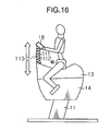
- a leg portion 11 of an oscillation-type exercise device 10 is mounted on an unillustrated floor surface and a driving device 12 as an exercise mechanism is fixed to the upper end of the leg portion 11.
- a seat portion 13 that imitates the shape of the back of a horse or the saddle for the user to be seated thereon is fixed to the top portion of the driving device 12.
- the driving device 12 is configured so as to oscillate the seat portion 13 in the front-rear direction and the right-left direction.
- the driving device 12 is covered with a cover 14 provided between the upper end of the leg portion 11 and the seat portion 13.
- the cover 14 is made of stretchable fabric or the like and allows for oscillation of the seat portion 13 induced by the driving device 12. It should be noted that the cover 14 is made of more than one material.
- a console device 15 is provided to the seat portion 13 in the top surface on the front side (on the left side in the drawing). Instructions to start and stop the driving device 12 and to change a motion condition are provided by operations on unillustrated switches provided to the console device 15.
- Reins 16 formed in the shape of a tube are provided to the front end of the seat portion 13.
- the reins 16 are provided to the seat portion 13 on both the right and left sides. In short, a pair of the reins 16 on the right and on the left are provided in this embodiment.
- the seat portion 13 is provided with an insertion hole 13a made on each of the right and left sides.
- the base ends of the respective reins 16 are inserted inside the seat portion 13 through the corresponding insertion holes 13a.
- the base ends of the respective reins 16 are coupled to extensible mechanisms 17 housed inside the seat portion 13.
- Two extensible mechanisms 17 are provided to correspond to the respective reins 16.
- Handle portions 18 are attached to the tip ends of the respective reins 16.
- Each handle portion 18 has a ring-like portion formed almost in the shape of a ring so as to be griped by the user.
- Fig. 1B shows the extensible mechanism 17 on the left side. Although the illustration of the extensible mechanism 17 on the right side is omitted herein, it is formed symmetric with respect to the extensible mechanism 17 on the left side.
- a motor 21 for extension and retraction in the extensible mechanism 17 is provided on the inner side of the seat portion 13 and fixed to the seat portion 13.
- a rotary plate 22 is fixed to the output shaft (not shown) of the motor 21 for extension and retraction.
- the base end of the rein 16 is coupled to a coupling portion 23 fixed to the rotary plate 22. The position at which the coupling portion 23 is fixed is set off center from the rotation center of the rotary plate 22.
- the base end of the rein 16 is fixed to the rotary plate 22 at a position displaced from the rotation center thereof in the radial direction. Accordingly, when the rotary plate 22 is rotated by the driving of the motor 21, the distance from the base end of the rein 16 to the insertion hole 13a varies. More specifically, the extensible mechanism 17 substantially extends or shortens the length of the rein 16 from the insertion hole 13a to the tip end thereof, that is, the length of the exposed portion of the rein 16.
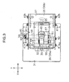
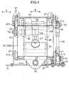
- the driving device 12 will be schematically described with Fig. 2 to Fig. 4 .
- a base 31 shaped like a rectangular plate is fixed to the top surface of the leg portion 11 shown in Fig. 1A , and as is shown in Fig. 2 , axial supporting plates 32 that make a pair in the front-rear direction are provided to stand on the base 31.
- a pair of coupling plates 34 provided to a movable stand 33 so as to droop down at the both end portions thereof in the front-rear direction is disposed oppositely to a pair of the axial supporting plates 32.
- the axial supporting plates 32 and the coupling plates 34 are coupled to each other in a rotatable manner by spindles 35 extending along the front-rear direction.
- the spindles 35 are disposed at two points in the front and the rear of the base 31 at the center in the right-left direction to support the movable stand 33 in a rotatable manner in the right-left direction.
- a pedestal 37 is supported on the movable stand 33 via a coupling link 36 in such a manner that oscillations in the front-rear direction are enabled.
- the pedestal 37 is disposed above the movable stand 33 and the seat portion 13 is attached to the pedestal 37.
- a pair of side plates 40 extending in the front-rear direction is provided to the movable stand 33 on both the right and left sides.
- the coupling link 36 has a front link 36a disposed frontward and a rear link 36b disposed rearward.
- the lower end portion of the front link 36a is attached to lower axial pins 41a provided to the front end portions of the side plates 40 in a rotatable manner.
- the upper end portion of the front link 36a is attached to upper axial pins 42a provided to the front end portion of the pedestal 37 in a rotatable manner.
- the lower end portion of the rear link 36b is attached to lower axial pins 41b provided to the rear end portions of the side plates 40 in a rotatable manner.
- the upper end portion of the rear link 36b is attached to the upper axial pins 42b provided to the rear end portion of the pedestal 37 in a rotatable manner.
- the respective lower axial pins 41a and 41b in the front and the rear respectively form left and right shafts that support the coupling link 36 in a rotatable manner about the axial line extending in the right-left direction Y.
- This configuration allows the pedestal 37 to move and rotate about the right and left shafts in a reciprocable manner.
- the pedestal 37 is allowed to oscillate in the front-rear direction (a direction indicated by an arrow M in Fig.
- the pedestal 37 rotates in the right-left direction integrally with the movable stand 33 owing to the coupling link 36.
- the pedestal 37 is therefore allowed to move and rotate about the spindles 35 supporting the movable stand 33 in a reciprocable manner.
- the pedestal 37 is allowed to oscillate in the right-left direction (a direction indicated by an arrow N in Fig. 4 )
- a center distance between the lower axial pins 41a and 41b in the front and the rear is set shorter than a center distance between the upper axial pins 42a and 42b in the front and the rear.
- the rear link 36b yields a specific angle with respect to the base 31. Accordingly, the rear end of the pedestal 37 becomes lower than the front end. In short, the pedestal 37 inclines rearward.
- the front link 36a yields a specific angle with respect to the base 31. Accordingly, the front end of the pedestal 37 becomes lower than the rear end. In short, the pedestal 37 inclines frontward.
- the seat portion 13 fixed to the pedestal 37 is thus inclined frontward and rearward.
- a driving portion 45 is accommodated in a space between the base 31 and the pedestal 37.
- the driving portion 45 is to oscillate the pedestal 37 with respect to the base 31.
- a motor 46 of the driving portion 45 is fixed to the base 31 so that an output shaft 47 thereof protrudes upward.
- a motor gear 48 is fixed to the output shaft 47.
- a first gear 50 is meshed with the motor gear 48.
- the first gear 50 is coaxially fixed to a first shaft 49 extending along the right-left direction and supported on the pedestal 37 at the both ends.
- An eccentric crank 51 is coupled to one end of the first shaft 49, and a first end portion of an arm link 53 is attached to the eccentric crank 51 by an axial pin 52 in a rotatable manner.
- a second end portion of the arm link 53 is attached to the front link 36a in a rotatable manner by an axial pin 54. Accordingly, the eccentric crank 51 undergoes eccentric circular motion with respect to the first shaft 49 with rotations of the motor 46.
- the front link 36a thus moves to reciprocate in the front-rear direction X, which causes the seat portion 13 to oscillate in the direction indicated by the arrow M in Fig. 2 .
- the motor 46 output shaft 47
- the motor gear 48, the first shaft 49, the first gear 50, the eccentric crank 51, and the arm link 53 together form a first driving portion.
- an interlocking gear 55 fixedly attached to the first shaft 49 is meshed with a second gear 57.
- the second gear 57 is fixed to a second shaft 56 supported on the movable stand 33.
- the upper end of an eccentric rod 58 is coupled to one end (right end in Fig. 4 ) of the second shaft 56.
- the eccentric rod 58 is set off center from the rotation center of the second shaft 56 by an axial pin 59.
- the lower end of the eccentric rod 58 is coupled to a coupling fitting 60 fixed to the base 31 by an axial pin 61 in a rotatable manner.
- the upper end of the eccentric rod 58 undergoes eccentric circular motion with rotations of the second shaft 56, which causes the movable stand 33, that is, the pedestal 37 and the seat portion 13, to oscillate in the direction indicated by the arrow N in Fig. 4 .
- the motor 46 output shaft 47
- the motor gear 48 the first gear 50
- the first shaft 49 the second shaft 56
- the second gear 57 the eccentric rod 58
- the respective gears in the first driving portion and the second driving portion are set to cause the seat portion 13 to reciprocate twice in the front-back direction while it reciprocates once in the right-left direction. Accordingly, when the oscillation-type exercise device 10 is viewed from above, the seat portion 13 is oscillated in a figure of eight to reproduce motion imitating the horseback riding.
- the seat portion 13 not only oscillates in the direction indicated by the arrow M in Fig. 2 but also oscillates in the direction indicated by the arrow N shown in Fig. 4 .
- the seat portion 13 is allowed to oscillate in a ⁇ X direction about the X axis, a ⁇ Y direction about the Y axis direction, and a ⁇ Z direction about the vertical axis (Z axis). It is thus possible to train the body balance function and the motor function of the user. Moreover, because three types of motion are enabled using the single motor 46, the number of the motors 46 can be lessened.
- the control can be simpler, but also the device can be reduced both in cost and size.
- the output shaft 47 of the motor 46 only has to protrude in one direction, the motor 46 can be installed in a longitudinal orientation. It is thus possible to reduce driving device 12 including the motor 46 in size by narrowing an overall installment space. Motion imitating the horseback riding can be therefore reproduced faithfully as intended by the driving device 12 accommodated in a space between the base 31 that supports the seat portion 13 and the pedestal 37.
- Fig. 5 is a block diagram showing the electrical configuration of the oscillation-type exercise device 10.
- a power supply circuit 81 mounted on a circuit board 71 converts a commercial alternating current inputted therein via a power source plug 72 to a direct current at 140V, 15V, and the like and supplies the converted direct current to respective circuits within the circuit board 71.
- a control circuit 82 mounted on the circuit board 71 includes a micro computer 82a and a memory 82b having recorded patterns of driving motion. It is connected to a console device control circuit 83, a motor driving circuit 84, a sensor signal processing circuit 85, another motor driving circuit 86, and another sensor signal processing circuit 87.
- a console device circuit 15a provided to the console device 15 shown in Fig. 1A is connected to the console device control circuit 83.
- the console device circuit 15a is provided with switches for operations and a display device, such as an LED, for displaying thereon a condition or the like.
- the motor driving circuit 84 is connected to the motor 46 for oscillation (see Fig. 2 ) described above.
- the motor 46 is provided with a sensor (not shown) to detect the rotation speed and the rotation position, and an output of the sensor is inputted into the sensor signal processing circuit 85.
- the motor driving circuit 86 is connected to the motors 21 for extension and retraction (see Fig. 1A ).
- Each motor 21 is provided with a sensor (not shown) to detect the rotation speed and the rotation position, and an output of the sensor is inputted into the sensor signal processing circuit 87.
- the control circuit 82 receives a signal corresponding to an operation on the switches of the console device circuit 15a via the console device control circuit 83.
- the control circuit 82 drives the motors 46 and 21 while controlling the numbers of rotations thereof via the motor driving circuits 84 and 86, respectively, under its control according to signals received from the console device control circuit 83 and the sensor signal processing circuits 85 and 87. Also, the control circuit 82 controls the display device of the console device 15 via the console device control circuit 83 to display thereon a motion condition or the like.
- the memory 82b of the control circuit 82 pre-stores parameters to control the motors 46 and 21 according to the patterns of driving motion.
- the control circuit 82 (substantially, the micro computer 82a) reads out the parameter corresponding to the operation on the switches provided to the console device 15 from the memory 82b, and drives the motors 46 and 21 via the motor driving circuits 84 and 86, respectively, under its control according to the parameter thus read out.
- one of the parameters stored in the memory 82b is a parameter to drive the motors 21 for extension and retraction shown in Fig. 1B .
- This parameter is set in such a manner that the rotary plates 22 shown in Fig. 1B rotate once while the seat portion 13 shown in Fig. 1A reciprocates once in the front-rear direction.
- One of the driving patterns stored in the memory 82b is to vary a tensile force of the reins 16 held by the user seated on the seat portion 13.
- the tensile force of the reins 16 varies with a change of the length of the reins 16 held by the user in a portion present on the outside of the seat portion 13. More specifically, when the control circuit 82 drives the motors 21 forming the extensible mechanisms 17 while the user seated on the seat portion 13 is holding the reins 16 (gripping the handle portions 18 attached to the tip ends), the reins 16 repetitively extend and retract in cycles with rotations of the motors 21 and the rotary plates 22. The user is therefore pulled frontward in response to retraction of the reins 16.
- the user feels a variance in tensile force of the reins 16.
- the extensible mechanisms 17 force the reins 16 to retract or extend against a force from the user pulling the reins 16. This motion forces the upper half of the body of the user to move, and thereby induces a muscle activity.
- the driving patterns are set so that the tensile force of the reins 16 varies with a movement of the seat portion 13. For example, as is shown in Fig. 6 , they are set so that the reins 16 extend (arrow A2) when the seat portion 13 moves frontward (arrow A1), and the reins 16 retract (arrow A4) when the seat 13 moves rearward (arrow A3).
- Fig. 7A For the user seated on the seat portion 13, as is shown in Fig. 7A , motion of the seat portion 13, motion of the upper portion of the dorsal vertebra of the user, and motion of the vertex of the head of the user are measured. Then, as is shown in Fig. 7B , there are phase shifts (delays) in motion among the seat portion 13, the upper portion of the dorsal vertebra, and the vertex of the head. The motion of the upper portion of the dorsal vertebra delays from the motion of the seat portion 13. Further, the motion of the vertex of the head is delayed from the motion of the upper portion of the dorsal vertebra.
- a delay of about 1/5 cycle and a delay of about 1/4 to 1/3 cycle occur in the upper portion of the dorsal vertebra and the vertex of the head, respectively.
- portions enclosed by a broken line in Fig. 7B indicate that the user actively catches up for a delay of the motion of the vertex of the head from the motion of the upper part of the dorsal vertebra.
- the base ends of a pair of reins 93 on the right and on the left are fixed to the front end of the seat portion 13 of an oscillation-type exercise device 91 of this embodiment.
- the reins 93 of this embodiment are made of a material having elasticity (rubber in this embodiment) and formed in a specific shape (for example, a tube-like shape).
- the handle portion 18 is attached to the tip end of each rein 93.
- the handle portion 18 has a ring-like portion formed almost in the shape of a ring so as to be gripped by the user.
- the length of the reins 93 when unstretched is set in such a manner that the elbows of the user are bent at about 90 degrees.
- the distance between the upper half of the body of the user and the seat portion 13 varies with shifts in motion (phase shifts) generated between the seat portion 13 and the upper half of the body with oscillations of the seat portion 13 in the same manner as described in the first embodiment above.
- a tensile force of the reins 93 can vary when the reins 93 having elasticity are used. Accordingly, motion (joint motion) and a muscle activity are induced in the upper half of the user in association with the motion of the oscillation-type exercise device 91. The user therefore becomes able to train the upper half of the body while minimizing his efforts like motion made with his will.
- the ordinate is used for ratio of the load by the exercise device to the load applied by the muscle training using dumbbells weighing 3 Kg in terms of the load expressed in percentage, and the abscissa is used for muscle regions and exercises to provide muscle activities to these muscle regions.
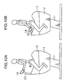
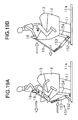
- the oscillation-type exercise device 91 when the user uses the oscillation-type exercise device 91 in the postures shown in Figs. 10A and 10B , muscle activities are induced in the pectoralis major, the biceps, and the muscle of the back. Hence, it can be expected that the upper arms are slimed down and the breasts are lifted up.
- Fig. 14 an amount of exercise in the state of Fig. 13B is indicted by an alternate long and short dash line and an amount of exercise in the state of Fig. 13A is indicated by a solid line as in Fig. 11 . It is understood from Fig. 14 that when the user uses the oscillation-type exercise device 91 in the posture shown in Fig.
- muscle activities are induced in the muscle of the back, the biceps, the trapezius, the deltoid, and the lateral borders of the scapula. Hence, it can be expected that the muscular strength in the respective regions can be increased.
- the reins 16 and 93 are formed in the shape of a tube in the respective embodiments above.
- the reins may be formed of a single string or plural strings either braided or unbraided.
- bars may be used instead of the reins 16. Further, reins and bars may be used in combination.
- stirrups 101 having loop portions for the user to put his feet in are provided.
- the stirrups 101 enable the user to hold the posture of the lower half of the body suitably during the oscillation exercise. The user therefore becomes able to practice exercise in a stable and correct posture.
- the user places his weight on the feet put in the stirrups 101, it is possible to intensively strengthen the quadriceps femoris that is closely related to the maintaining of the walking ability and prevention of gonalgia (pain in the knees).
- a rein 102 shaped like a loop may be used.
- the user With the rein 102 formed in this manner, the user directly grips the rein 102 and holds the rein 102. Owing to the loop-like rein 102 and the stirrups 101, the user can manage the horseback riding posture as if he were riding on a real horse without having uncomfortable feeling.
- the reins 93 are made of rubber in order to provide elasticity.
- reins 110 using springs 111, either entirely or partially, and covers 112 that cover the corresponding springs 111. It may be configured so as to provide the stirrups 101 to an exercise device having the reins 110 as is shown in Fig. 17A .
- a rein 121 shaped like a loop and made of a spring may be used as well.
- reins 131 formed by combining springs 132 and a bar 133 may be used.
- the second embodiment above it is configured in such a manner that the base ends of the reins 93 are fixed to the tip end on the top surface of the seat portion 13.
- it may be configured in such a manner that reins 141 are coupled to the seat portion 13 in a detachable manner.
- plural fixing portions 142 as fixing members are provided to the front end of the seat portion 13, and the reins 141 are formed so that they can be coupled to any of the fixing portions 142. The user therefore becomes able to select the fixing portions 142 to which the reins 141 are coupled.
- the reinforcement 18B it may be configured in such a manner that plural hinge pins 143 as fixing members are provided to the tip end of the seat portion 13 while a locking hole 145 is made in the base end of each rein 144.
- the fixed positions of the reins 144 can be changed by selecting the hinge pins 143 to which the reins 144 are coupled.
- the length of the reins may be changed.
- more than one locking hole 145 may be made in each rein in the configuration of Fig. 18B .
- the posture to hold the reins is changed, and so is the muscle used to hold the reins.
- the training can have a variation.
- the base ends of the reins are disposed at the front end portion of the seat portion 13 in the respective embodiments above.
- the invention is not limited to this configuration. As long as the reins are disposed in front of the user seated on the seat portion 13, the reins may be attached to points slightly displaced rearward from the front end portion of the seat portion 13.
- an extensible mechanism 151 may be provided to the base 11a of the leg portion 11.
- a support portion 152 that supports the extensible mechanism 151 is provided to stand on the base 11a.
- An arm member 153 as a first member is supported on the supporting portion 152 in a rotatable manner. The base ends of the reins 16 are fixed to the tip end of the arm member 153.
- the base end of the arm member 153 is coupled to the lower end (second end) of a shaft 154 as a second member in a rotatable manner.
- the upper end (first end) of the shaft 154 is coupled to the driving device 12 (or the cover 14) in a rotatable manner.
- the arm member 153 oscillates via the driving device 12 (or the cover 14) with rotations of the motor 46, which not only causes the seat portion 13 to oscillate, but also causes the reins 16 to extend and retract.
- the number of the motors 46 can be lessened.
- it may be configured in such a manner that a motor is provided to an extensible mechanism fixed to the base.
- the handle portions attached to the reins may be formed so that they can be also used as the stirrups.
- the handle portions may function as the loop portions in which the user puts his feet.
- the oscillation of the seat portion 13 and the extension and retraction of the reins 16 are brought into synchronization.
- the cycles of extension and retraction of the reins 16, that is, the rotation cycles of the motors 21 for extension and retraction can be changed.
- the rotation cycles may be changed by a selection of the mode (the modes for beginners, for experienced users, and so forth).
- the rotation positions of a pair of the motors 21 on the right and on the left forming the extensible mechanisms 17 may be changed.
- the reins 16 on the right and on the left extend and retract separately, and the upper half of the body of the user is forced to twist. The user thus becomes able to train muscles relating to turning motion of the trunk.
- an oscillation-type exercise device capable of exerting an exercise effect not only to the lower back and the legs but also to the upper half of the body.
Landscapes
- Health & Medical Sciences (AREA)
- General Health & Medical Sciences (AREA)
- Physical Education & Sports Medicine (AREA)
- Rehabilitation Tools (AREA)
Applications Claiming Priority (1)
| Application Number | Priority Date | Filing Date | Title |
|---|---|---|---|
| JP2007140508A JP4349435B2 (ja) | 2007-05-28 | 2007-05-28 | 揺動型運動装置 |
Publications (1)
| Publication Number | Publication Date |
|---|---|
| EP1997540A1 true EP1997540A1 (de) | 2008-12-03 |
Family
ID=39684372
Family Applications (1)
| Application Number | Title | Priority Date | Filing Date |
|---|---|---|---|
| EP08009640A Withdrawn EP1997540A1 (de) | 2007-05-28 | 2008-05-27 | Schwingendes Übungsgerät |
Country Status (6)
| Country | Link |
|---|---|
| US (1) | US7828705B2 (de) |
| EP (1) | EP1997540A1 (de) |
| JP (1) | JP4349435B2 (de) |
| KR (1) | KR101020960B1 (de) |
| CN (2) | CN101314072A (de) |
| TW (1) | TW200911324A (de) |
Families Citing this family (5)
| Publication number | Priority date | Publication date | Assignee | Title |
|---|---|---|---|---|
| CN103750978A (zh) * | 2014-01-08 | 2014-04-30 | 张倩 | 一种人型骨科康复装置 |
| CN105903194A (zh) * | 2016-06-15 | 2016-08-31 | 东北大学 | 一种骑马游戏模拟器 |
| DE102016213964A1 (de) * | 2016-07-28 | 2018-02-01 | Kuka Roboter Gmbh | Hippotherapievorrichtung |
| CN106110619A (zh) * | 2016-08-20 | 2016-11-16 | 姚前 | 一种骑驯方法和装置 |
| KR102149785B1 (ko) * | 2020-04-10 | 2020-08-31 | 전우식 | 헬스바이크 안장의 좌우요동 폭 조절 및 회동 구조 |
Citations (6)
| Publication number | Priority date | Publication date | Assignee | Title |
|---|---|---|---|---|
| GB191205291A (en) | 1912-03-02 | 1913-01-23 | Haydock Wilbe | A New or Improved Mechanical Horse Exercising Apparatus. |
| GB195215A (en) | 1922-01-31 | 1923-03-29 | James Ashton Fletcher | Improvements in apparatus for amusement and recreation purposes |
| US4988300A (en) | 1988-12-15 | 1991-01-29 | Meitec Corporation | Riding simulator |
| JP2001286578A (ja) | 2000-04-07 | 2001-10-16 | Matsushita Electric Works Ltd | バランス訓練装置 |
| US20040101811A1 (en) | 2002-11-21 | 2004-05-27 | Gipson Tommie C. | Mechanical dally coach |
| JP2005245638A (ja) | 2004-03-02 | 2005-09-15 | Fujii Kinzoku Kako Kk | 電動椅子 |
Family Cites Families (23)
| Publication number | Priority date | Publication date | Assignee | Title |
|---|---|---|---|---|
| US701267A (en) * | 1901-08-23 | 1902-05-27 | Curran Pope | Sheet-metal fastening-cleat. |
| US710267A (en) * | 1902-02-18 | 1902-09-30 | Alois Graf | Apparatus for training horses. |
| GB191305291A (en) * | 1913-03-03 | 1913-06-12 | Max Buch | Improvements in Cape Cart Hoods for use on Motor Vehicles and the like. |
| US2127056A (en) * | 1936-12-05 | 1938-08-16 | Davis Grover | Toy vehicle |
| US2552002A (en) * | 1946-03-15 | 1951-05-08 | Karl E Dunbar | Hobbyhorse |
| US2788217A (en) * | 1955-06-06 | 1957-04-09 | Harry W Patterson | Ridable hobby horse |
| US3149837A (en) * | 1960-11-01 | 1964-09-22 | Carl H Kramm | Coin-controlled hobby horse |
| US3161005A (en) * | 1963-07-12 | 1964-12-15 | Richard E Ackerson | Electric animal training device |
| US4304193A (en) * | 1980-11-17 | 1981-12-08 | Madden Lem A | Remote control apparatus for controlling animals |
| US4431182A (en) * | 1982-05-03 | 1984-02-14 | Reynolds Francis D | Human free-flight amusement devices |
| JPH02228987A (ja) | 1989-03-03 | 1990-09-11 | Meitec Corp | ライディングシミュレータにおける人工馬体の手綱動作検出装置 |
| JPH03102908U (de) | 1990-02-09 | 1991-10-25 | ||
| JP3102908B2 (ja) | 1991-06-07 | 2000-10-23 | 森下仁丹株式会社 | 3−フェニルプロペナール誘導体を有効成分とする抗潰瘍剤 |
| US5533899A (en) * | 1995-06-01 | 1996-07-09 | Young; Jerry | Motorcycle trainer |
| JPH10127713A (ja) | 1996-10-28 | 1998-05-19 | Matsushita Electric Works Ltd | 運動機能賦活方法および運動機能賦活装置 |
| US6059666A (en) * | 1997-02-21 | 2000-05-09 | Namco Ltd. | Riding game system |
| JP3394890B2 (ja) | 1997-06-18 | 2003-04-07 | 松下電工株式会社 | 腰痛予防訓練装置 |
| GB2380140B (en) * | 2000-06-29 | 2004-03-10 | William Ronald Greenwood | Polo training apparatus |
| KR200337159Y1 (ko) | 2003-07-16 | 2003-12-31 | 지용구 | 운동용 승마기구 |
| JP4039428B2 (ja) | 2004-07-27 | 2008-01-30 | 松下電工株式会社 | 揺動型運動装置 |
| JP4258464B2 (ja) | 2004-11-25 | 2009-04-30 | パナソニック電工株式会社 | 揺動型運動装置 |
| JP4483815B2 (ja) | 2006-03-28 | 2010-06-16 | パナソニック電工株式会社 | 揺動型運動装置 |
| KR200428012Y1 (ko) | 2006-07-05 | 2006-10-04 | 강수정 | 로데오형 완구 |
-
2007
- 2007-05-28 JP JP2007140508A patent/JP4349435B2/ja not_active Expired - Fee Related
-
2008
- 2008-05-26 TW TW097119339A patent/TW200911324A/zh unknown
- 2008-05-27 US US12/127,146 patent/US7828705B2/en not_active Expired - Fee Related
- 2008-05-27 KR KR1020080049092A patent/KR101020960B1/ko not_active Expired - Fee Related
- 2008-05-27 EP EP08009640A patent/EP1997540A1/de not_active Withdrawn
- 2008-05-27 CN CNA2008101095319A patent/CN101314072A/zh active Pending
- 2008-05-27 CN CNU2008201198039U patent/CN201239472Y/zh not_active Expired - Fee Related
Patent Citations (6)
| Publication number | Priority date | Publication date | Assignee | Title |
|---|---|---|---|---|
| GB191205291A (en) | 1912-03-02 | 1913-01-23 | Haydock Wilbe | A New or Improved Mechanical Horse Exercising Apparatus. |
| GB195215A (en) | 1922-01-31 | 1923-03-29 | James Ashton Fletcher | Improvements in apparatus for amusement and recreation purposes |
| US4988300A (en) | 1988-12-15 | 1991-01-29 | Meitec Corporation | Riding simulator |
| JP2001286578A (ja) | 2000-04-07 | 2001-10-16 | Matsushita Electric Works Ltd | バランス訓練装置 |
| US20040101811A1 (en) | 2002-11-21 | 2004-05-27 | Gipson Tommie C. | Mechanical dally coach |
| JP2005245638A (ja) | 2004-03-02 | 2005-09-15 | Fujii Kinzoku Kako Kk | 電動椅子 |
Also Published As
| Publication number | Publication date |
|---|---|
| JP4349435B2 (ja) | 2009-10-21 |
| CN201239472Y (zh) | 2009-05-20 |
| KR20080104984A (ko) | 2008-12-03 |
| US20080300119A1 (en) | 2008-12-04 |
| CN101314072A (zh) | 2008-12-03 |
| US7828705B2 (en) | 2010-11-09 |
| JP2008289787A (ja) | 2008-12-04 |
| KR101020960B1 (ko) | 2011-03-09 |
| TW200911324A (en) | 2009-03-16 |
Similar Documents
| Publication | Publication Date | Title |
|---|---|---|
| JP4530010B2 (ja) | 揺動型運動装置 | |
| US20080103034A1 (en) | Balance Fitness Machine | |
| JP4270113B2 (ja) | 揺動型運動装置 | |
| KR101044094B1 (ko) | 하체 근력강화 운동기구 | |
| JP4483815B2 (ja) | 揺動型運動装置 | |
| TWI401103B (zh) | Sports device | |
| US7828705B2 (en) | Oscillation-type exercise device | |
| JP4492655B2 (ja) | 揺動型運動装置 | |
| KR100977046B1 (ko) | 승마형 운동기구 | |
| KR20170052289A (ko) | 자전거형 승마운동기구 | |
| JP4492659B2 (ja) | 揺動型運動装置 | |
| CN202128670U (zh) | 一种平行振动机 | |
| JP5123187B2 (ja) | 運動装置 | |
| JP4483814B2 (ja) | 揺動型運動装置 | |
| JP2009028093A (ja) | 揺動型運動装置 | |
| JP5032233B2 (ja) | 揺動型運動装置用補助器具及び揺動型運動システム | |
| JP3149964U (ja) | 運動器具の揺動式ハンドル装置 | |
| JP4831021B2 (ja) | 揺動型運動装置 | |
| US12465542B1 (en) | Combined abdominal exerciser and treadmill | |
| JP2020065912A (ja) | 運動器具、および運動器具セット | |
| JP2009050443A (ja) | 揺動型運動装置用補助器具及び揺動型運動システム | |
| JP2007260186A (ja) | バランス訓練装置 | |
| JP2009077828A (ja) | 揺動型運動装置 | |
| JP2009056184A (ja) | 揺動型運動装置 | |
| JP2009056183A (ja) | 揺動型運動装置 |
Legal Events
| Date | Code | Title | Description |
|---|---|---|---|
| PUAI | Public reference made under article 153(3) epc to a published international application that has entered the european phase |
Free format text: ORIGINAL CODE: 0009012 |
|
| AK | Designated contracting states |
Kind code of ref document: A1 Designated state(s): AT BE BG CH CY CZ DE DK EE ES FI FR GB GR HR HU IE IS IT LI LT LU LV MC MT NL NO PL PT RO SE SI SK TR |
|
| AX | Request for extension of the european patent |
Extension state: AL BA MK RS |
|
| 17P | Request for examination filed |
Effective date: 20081223 |
|
| RAP1 | Party data changed (applicant data changed or rights of an application transferred) |
Owner name: PANASONIC ELECTRIC WORKS CO., LTD. |
|
| AKX | Designation fees paid |
Designated state(s): AT BE BG CH CY CZ DE DK EE ES FI FR GB GR HR HU IE IS IT LI LT LU LV MC MT NL NO PL PT RO SE SI SK TR |
|
| 17Q | First examination report despatched |
Effective date: 20100510 |
|
| RAP1 | Party data changed (applicant data changed or rights of an application transferred) |
Owner name: PANASONIC CORPORATION |
|
| STAA | Information on the status of an ep patent application or granted ep patent |
Free format text: STATUS: THE APPLICATION IS DEEMED TO BE WITHDRAWN |
|
| 18D | Application deemed to be withdrawn |
Effective date: 20130619 |