EP1997552A2 - Sauerstoffisotop-Konzentrationsverfahren - Google Patents
Sauerstoffisotop-Konzentrationsverfahren Download PDFInfo
- Publication number
- EP1997552A2 EP1997552A2 EP08015904A EP08015904A EP1997552A2 EP 1997552 A2 EP1997552 A2 EP 1997552A2 EP 08015904 A EP08015904 A EP 08015904A EP 08015904 A EP08015904 A EP 08015904A EP 1997552 A2 EP1997552 A2 EP 1997552A2
- Authority
- EP
- European Patent Office
- Prior art keywords
- ozone
- oxygen
- oxygen isotope
- peroxide
- unit
- Prior art date
- Legal status (The legal status is an assumption and is not a legal conclusion. Google has not performed a legal analysis and makes no representation as to the accuracy of the status listed.)
- Withdrawn
Links
Images


Classifications
-
- B—PERFORMING OPERATIONS; TRANSPORTING
- B01—PHYSICAL OR CHEMICAL PROCESSES OR APPARATUS IN GENERAL
- B01D—SEPARATION
- B01D59/00—Separation of different isotopes of the same chemical element
- B01D59/34—Separation by photochemical methods
Definitions
- the present invention relates to a method for concentrating oxygen isotopes, and more particularly, to a method for selectively concentrating the stable oxygen isotopes, 17 O and/or 18 O, which exist in extremely small natural abundance, by using an ozone photodissociation reaction or a peroxide photodissociation reaction.
- a known method for concentrating 18 O consists of obtaining a product that contains 18 O by selectively photodissociating a saturated chain ether that contains 18 O by irradiating it with laser light (refer to, for example, Japanese Examined Patent Application, Second Publication No. 6-102134 ).
- Other methods include a method for selectively concentrating 18 O by irradiating formaldehyde or carbon monoxide with laser light.
- the object of the present invention is to provide a method for concentrating oxygen isotopes that are capable of concentrating a oxygen isotope either in the state of the stable oxygen isotopes of 17 O or 18 O, or in a substance such as water having a simple molecular structure.
- the oxygen isotope concentration method of the present invention comprises (a) an ozone photodissociation step, in which ozone molecules containing oxygen isotopes, 17 O and/or 18 O, are selectively photodissociated to oxygen molecules; thereby generating a mixture of the oxygen molecules and non-dissociated ozone molecules, followed by (b) an oxygen isotope concentration step, in which the oxygen molecules are separated from the mixture, thereby concentrating the oxygen isotope.
- the present invention comprises (A) an ozone formation step, in which ozone is produced from raw material oxygen, thereby forming a mixture of the produced ozone and the raw material oxygen, (B) an ozone separation step, in which the produced ozone is separated from the mixture, (C) an ozone photodissociation step, in which ozone molecules containing oxygen isotopes, 17 O and/or 18 O, are selectively photodissociated to oxygen molecules; thereby generating a mixture of the oxygen molecules and non-dissociated ozone molecules, and (D) an oxygen isotope concentration step, in which the oxygen molecules are separated from the mixture obtained in the step (C), thereby concentrating the oxygen isotope.
- Different oxygen isotopes can also be concentrated in two stages by carrying out (E) a second ozone photodissociation step, in which the non-dissociated ozone molecules containing an oxygen isotope that is different from one separated in the step (D) are photodissociated to oxygen molecules, thereby generating a mixture of the oxygen molecules and non-dissociated ozone molecules, and (F) a second oxygen isotope concentration step, in which the oxygen molecules are separated from the mixture obtained in the step (E), thereby concentrating the oxygen isotope that is different from one separated in the step (D).
- the oxygen isotope concentration method of the present invention may also contain an oxygen isotope concentration step in which ozone is irradiated with light after adding at least one type of krypton, xenon or radon rare gas in the photodissociation step (a) or (B), thereby generating a mixture of the oxygen molecules, non-dissociated ozone molecules, and the rare gas; and the oxygen molecules obtained in the ozone photodissociation step is separated from the mixture.
- the oxygen isotope concentration step (b) or (D) may be distillation in which at least one type of helium, neon or argon rare gas is added for the oxygen isotope concentration step.
- At least one type of rare gas selected from helium, neon, argon or krypton is added to the raw material oxygen in the step (A).
- the light used in the ozone photodissociation step (a) or (C) is preferably either light within a range of 700-1000 nm, or light within a range of 450-850 nm.
- the wavelength of the light used in the ozone photodissociation step is more preferably within the range of 991.965 to 992.457 nm. It is also preferable to adjust the absorption wavelength of ozone by applying an electric field in the ozone photodissociation step (a) or (C). It is also preferable to carry out the ozone photodissociation step (a) or (C) at low temperature and low pressure.
- the oxygen molecules containing a desired oxygen isotope, 17 O or 18 O can be photodissociated by irradiating ozone molecules containing a mixture of these various types of isotopomers with light.
- the 17 O that composed the ozone that was photodissociated in reaction formula (1) is either contained in the formed "O 2 " or is in the form of "O". Since this "O" immediately reacts with other ozone to form two molecules of oxygen as shown in reaction formula (2), this means that the 17 O is present in one of the three molecules of oxygen formed in reaction formulas (1) and (2). Although there is the possibility of 17 O or 18 O also being contained in the ozone that reacts in reaction formula (2), the probability is extremely low such that the amount can be ignored.
- the bond dissociation energy of ozone is 1.05 eV, and ozone breaks down during absorption of light having a wavelength of 1.18 ⁇ m or less. This light absorption by ozone is known to take place in the bands indicated below.
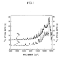
- Fig. 1 shows the optical absorbance for 16 O 3 ( 16 O 16 O 16 O) and 18 O 3 ( 18 O 18 O 18 O).
- the maximum peak of 16 O 3 can be seen to be at a wave number of 10081 cm -1 (wavelength: 991.965 nm), while the maximum peak of 18 O 3 can be seen to be at a wave number of 10076 cm -1 (wavelength: 992.457 nm).
- the wavelength at which an isotopomer of ozone containing 17 O or 18 O can be efficiently dissociated is located between these two, and it can be seen that the desired ozone can be selectively dissociated by selecting a wavelength within that range.
- the aforementioned range is optimal.
- there is also the advantage of such light in the near infrared or visible band being easier to handle in comparison with the case of using light of the ultraviolet band.
- ultraviolet light of a high energy level is used, in addition to the target ozone isotopomer, other ozone isotopomers may also end up being dissociated, thereby lowering the concentration efficiency of the oxygen isotope.
- the absorption wavelength of ozone can be shifted using the Stark effect by applying an electric field to the ozone when irradiating with light, the absorption wavelength of the ozone can be made to precisely match the wavelength of the light source.
- Examples of light sources that can be used to obtain light of this wavelength include spectral light of sunlight as well as colored laser light capable of optical pumping with an InGaAsP semiconductor laser or light emitting diode, AlGaInP semiconductor laser or light emitting diode, GaAsSb semiconductor laser or light emitting diode, CdZnTe semiconductor laser or light emitting diode, CdZnSe semiconductor laser or light emitting diode, mercury lamp, YAG laser, Ar ion laser or Kr ion laser.
- light is preferably radiated at a low pressure of, for example, 13 kPa (100 Torr) or less in order to lengthen the mean free path of the ozone molecules and suppress molecular collisions as much as possible.
- a low pressure of, for example, 13 kPa (100 Torr) or less
- the formation of oxygen by spontaneous dissociation can be suppressed, thereby making it possible to improve the concentration rate of oxygen containing oxygen isotopes.
- Ozone can be formed easily by silent discharge of oxygen serving as the material with an ozonizer, or by irradiating with ultraviolet light from a mercury lamp and so forth.
- oxygen of high purity that contains as few impurities such as argon and nitrogen as possible is preferably used for the raw material oxygen, if these impurities can be adequately separated when separating the ozone and oxygen, then industrial oxygen having a purity of about 99.5% can also be used for the raw material oxygen.
- Oxygen consisting of 17 O or 18 O concentrated with the concentration method of the present invention as well as oxygen consisting of 17 O or 18 O concentrated with other methods can be used for the raw material oxygen.
- Separation of ozone and oxygen or separation of oxygen, ozone and rare gas can be easily carried out by low-temperature distillation utilizing the difference in boiling points between them, or by low-temperature adsorption utilizing their differences in adsorption to an adsorbent such as silica gel.
- the optimum device configuration for carrying out the present invention is provided with an ozone formation unit 11 that forms ozone from raw material oxygen GO, an ozone separation unit 12 that separates ozone OZ formed with the ozone generation unit and raw material oxygen, an ozone photodissociation unit 13 that radiates light L of a specific wavelength onto the ozone separated by ozone separation unit 12 and selectively degrades ozone containing a specific oxygen isotope in its molecule into oxygen, and an oxygen separation unit 14 that separates the oxygen OC formed by degrading ozone in ozone photodissociation unit 13 and non-dissociated ozone OZ to concentrate the desired oxygen isotope in the oxygen.
- the device configuration for carrying out the present invention can also be provided with a second ozone photodissociation unit 15, which radiates light L onto ozone OZ separated by oxygen separation unit 14 and selectively degrades ozone that contains in its molecule a different oxygen isotope from the ozone dissociated by the ozone photodissociation unit 13 into oxygen, and a second oxygen separation unit 16, which separates oxygen OC2 formed by the dissociation of ozone in the second ozone photodissociation unit 15 and non-dissociated OZ2 to concentrate an oxygen isotope in the oxygen.
- a second ozone photodissociation unit 15 which radiates light L onto ozone OZ separated by oxygen separation unit 14 and selectively degrades ozone that contains in its molecule a different oxygen isotope from the ozone dissociated by the ozone photodissociation unit 13 into oxygen
- a second oxygen separation unit 16 which separates oxygen OC2 formed by the dissociation of o
- the amount of raw material oxygen consumed can be reduced by providing a line by which oxygen GO separated by ozone separation unit 12 is recycled and fed into ozone formation unit 11.
- Ozone photodissociation unit 13 is preferably provided with a cooling unit and a pressure reduction unit.
- ozone having as high a purity as possible in consideration of the radiation efficiency of the light and the concentration efficiency
- the use of highly pure ozone may result in spontaneous dissociation due to catalysis with metal surfaces having catalytic action. If oxygen not containing the desired oxygen isotope is formed in large amounts due to spontaneous dissociation of ozone, this oxygen can cause a considerable decrease in the concentration rate in the aforementioned oxygen isotope concentration step.
- ozone concentration can be lowered by adding a suitable amount of a rare gas to the ozone in order to prevent in advance any decreases in the concentration rate of oxygen isotopes caused by spontaneous dissociation of ozone.
- rare gases helium, neon, argon, krypton, xenon and radon
- a specific ozone can be still be selectively dissociated even if the ozone is diluted with these rare gases.
- handling of the ozone can be made easier as compared with highly pure ozone by diluting it with a rare gas.
- ozone and rare gas can be carried out with an arbitrary device of each step, and a rare gas suitable for each step should be added in a suitable amount.
- rare gases that solidify at low temperatures, rare gases that condense at locations where they should be gaseous, and rare gases that vaporize at locations where they should be a liquid are unsuitable, and it is necessary to select rare gases according to the operating pressure and operating temperature.
- a rare gas that is concentrated on the gas phase side may be used in combination.
- xenon and radon are not preferable for use in the ozone formation step since they form unstable compounds by reacting with oxygen that is caused by silent discharge with an ozonizer or irradiation with ultraviolet light from a mercury lamp and so forth.
- the oxygen isotope concentration device for carrying out the present invention can be provided with an ozone photodissociation unit, which radiates light onto a rare gas-ozone mixed gas containing ozone and at least one type of rare gas selected from krypton, xenon and radon, and selectively degrades ozone containing a specific oxygen isotope in its molecule into oxygen, and an oxygen isotope concentration unit, which separates the oxygen separated from ozone in the ozone photodissociation unit from non-dissociated ozone to concentrate the oxygen isotope present in the separated oxygen.
- an ozone photodissociation unit which radiates light onto a rare gas-ozone mixed gas containing ozone and at least one type of rare gas selected from krypton, xenon and radon, and selectively degrades ozone containing a specific oxygen isotope in its molecule into oxygen
- an oxygen isotope concentration unit which separates the oxygen separated from o
- Still another oxygen isotope concentration method of the present invention comprises photodissociation of peroxide with semiconductor laser light, and thereby increasing the concentration of an oxygen isotope in a photoreaction product.
- the peroxide examples include at least one type of organic peroxide such as hydroperoxides such as HOOH and (CH 3 ) 3 COOH, (di)alkyl peroxides such as CH 3 OOCH 3 , C 2 H 5 OOC 2 H 5 and (CH 3 ) 3 OO(CH 3 ) 3 , peroxyacids including peracids such as HCOOOH and CH 3 OOOH, (di)acyl peroxides such as CH 3 OOOCOCH 3 and peroxyesters such as CH 3 OOOC(CH 3 ) 3 , (CH 3 ) 2 CHCOOOC(CH 3 ) and (CH 3 ) 3 C-COOOC(CH 3 ) 3 , peroxycarbonates such as (CH 3 ) 3 COOCOOCH(CH 3 ) 2 , peroxydicarbonates such as diperoxycarbonates such as i-PrO-COOOCOO-i-Pr (i-Pr: isopropyl group), peroxalates,
- the aforementioned peroxides may be diluted with at least one type of solvent selected from carbon tetrachloride, acetone, acetic acid, hexane, toluene and chlorofluorocarbons, or organic substances having a double bond, and the aforementioned dissociation is predissociation.
- the method further comprises
- Fig. 3 is a system diagram showing a first embodiment of the oxygen isotope concentration device of the present invention.
- This concentration device is provided an ozonizer 21 for obtaining ozone from raw material oxygen, a first distillation tower 22 that separates the ozone formed with this ozonizer 21 and the raw material oxygen, a condenser 23 for imparting the cold required by the low-temperature distillation procedure in this first distillation tower 22, a reboiler 24 for generating rising gas in the first distillation tower, a heat exchanger 25 for recovering the cold of the first distillation tower effluent gas in the first distillation tower feed gas, a buffer tank for temporarily storing the first distillation tower effluent gas, and a blower 27 for circulating and feeding first distillation tower effluent gas in buffer tank 26 to ozonizer 21.
- the equipment for concentrating oxygen containing a specific isotope from the ozone is provided with a photoreaction cell 32 for separating a specific ozone isotopomer into oxygen by light radiated from light source 31, a second distillation tower 33 that separates the oxygen formed in photoreaction cell 32 from non-dissociated ozone to concentrate the oxygen isotope in the oxygen, a condenser 34 for imparting the cold required by the low-temperature distillation procedure in second distillation tower 33, a reboiler 35 for generating rising gas in the second distillation tower, and a heat exchanger 36 for recovering the cold of the second distillation tower effluent gas in the second distillation tower feed gas.
- This ozone-oxygen mixed gas is distilled by a refluxing liquid formed with condenser 23 located above the first distillation tower and a rising gas formed in reboiler 24 located beneath the first distillation tower, and the liquefied ozone of the oxygen gas in the upper portion of first distillation tower 22 respectively separates in the bottom of first distillation tower 22.
- the specific isotopomer present in this ozone is dissociated into oxygen by light radiated from light source 31, and the ozone-oxygen mixed gas composed of dissociated oxygen and non-dissociated ozone is led out from line 58 through valve 59.
- the inside of the photoreaction cell 32 in order to carry out dissociation of a specific isotopomer of ozone efficiently in a stable state, together with reducing the pressure to 13 kPa or less, the inside of the photoreaction cell is cooled to within a range of 100-250 K.
- Pressure and temperature may be suitably set according to the dissociation status of the ozone, and at least the area between photoreaction cell 32 and valves 57 and 59 on both sides should be maintained at a predetermined pressure and predetermined temperature within ranges that do not cause the ozone to liquefy or solidify.
- the ozone-oxygen mixed gas of line 58 is fed into the intermediate stage of second distillation tower 33 after being cooled with heat exchanger 36, and similar to the aforementioned first distillation tower 21, is distilled by a refluxing liquid from condenser 34 and a rising gas from reboiler 35, causing ozone to separate in the lower portion of the tower and oxygen gas containing a specific oxygen isotope to concentrate in the upper portion of the tower.
- the concentrated oxygen gas containing a specific isotope is discharged from the upper portion of second distillation tower 33 into line 61, and after a portion of the gas has branched to condenser 34, is recovered in the form of a product from line 62. After a portion of the ozone that has been discharged from the bottom of second distillation tower 33 into line 63 has branched to reboiler 35, the remainder is removed to line 64 after passing through heat exchanger 36.
- the ozone of line 64 is normally discharged after being dissociated into oxygen by an ozone photodissociation unit using a catalyst and so forth.
- the ozone of this line 64 can also be fed into a second photoreaction cell (not shown) serving as a second photodissociation unit provided separately from the aforementioned photoreaction cell 32, an isotopomer can be dissociated that differs from that dissociated in photoreaction cell 32, and the isotope-containing oxygen formed by this dissociation can be separated from the ozone and concentrated by using a second oxygen separation unit in the form of a distillation tower and so forth.
- each distillation tower since the concentration of the desired isotope-containing oxygen gas decreases if oxygen enters the photoreaction cell, it is preferable obtain ozone in a state that is as free of oxygen as possible.
- Nitrogen or argon at a suitable temperature can be used for the cooling source supplied to the condenser and the heating source supplied to reboiler. Nitrogen or argon at a suitable temperature can also be used for cooling the photoreaction cell.
- Reduction of pressure inside the system that contains the photoreaction cell can be carried out by installing a vacuum pump in a suitable line downstream from the photoreaction cell or by reducing the pressure by liquefaction using liquid nitrogen and so forth.
- a material that does not exhibit reactivity or catalytic action with ozone should be selected for the materials of the equipment, and normally glass or fluororesin ((polytetrafluoroethylene) and so forth is used preferably.
- the optical path length was 40 m
- the retention time was 100 seconds
- the light utilization rate was 0.0019
- the yield of the target isotopomer was 0.90
- the amount of non-selective dissociation of other isotopomers generated simultaneous to dissociation of the target isotopomer was 3.3 with respect to a value of 1 for the target isotopomer.
- the concentration rate of 17 O at this time was 10.8.
- the amount of power consumed by the ozonizer was 3.0 kW.
- Table 1 Line Number 51 52 53 55 56 58 64 62 Flow Rate mol/s 5.50E-04 3.85E-03 3.87E-03 3.30E-03 3.87E-03 3.69E-04 3.61E-04 8.42E-06 No.
- the optical path length was 40 m
- the retention time was 100 seconds
- the light utilization rate was 0.0003
- the yield of the target isotopomer was 0.90
- the amount of non-selective dissociation of other isotopomers generated simultaneous to dissociation of the target isotopomer was 10 with respect to a value of 1 for the target isotopomer.
- the concentration rate of 17 O at this time was 85.4.
- the amount of power consumed by the ozonizer was 6.7 kW.
- Table 2 Line Number 51 52 53 55 56 58 64 62 Flow Rate mol/s 1.22E-03 8.54E-03 8.13E-03 7.32E-03 8.13E-04 8.16E-04 8.07E-04 8.89E-06 No.
- Fig. 4 is a system diagram showing a second embodiment of an oxygen isotope concentration device. It shows an example of the configuration of a device provided with equipment for obtaining a rare gas-ozone mixed gas in a stage prior to the concentration device.
- This concentration device together with being provided with an ozone formation unit 111 that forms ozone from raw material oxygen GO, an ozone separation unit 112 that separates raw material oxygen containing ozone formed in said ozone formation unit 111 into ozone OZ and raw material oxygen RO, an ozone photodissociation unit 113 that selectively degrades ozone containing a specific oxygen isotope in its molecule into oxygen by irradiating the ozone OZ separated in said ozone separation unit 112 with light L of a specific wavelength, and an oxygen isotope concentration unit 114 that separates oxygen OC formed by the dissociation of ozone in said ozone photodissociation unit 113 from non-dissociated ozone OZ to concentrate a desired oxygen isotope in said oxygen, is also provided with a line 115 that feeds raw material oxygen into ozone formation unit 111, a line 116 that feeds ozone-containing oxygen formed in ozone formation unit 111 into ozone
- rare gas feed line 117 among the aforementioned three rare gas feed lines 117, 118 and 119, a rare gas other than xenon and radon, for which there is the risk of oxidation or disintegration in ozone formation unit 111 (ozone formation step), is mixed alone or as a plurality of types and added to the raw material oxygen.
- rare gas feed line 118 it is preferable that a rare gas be added that can be supplied to ozone photodissociation unit 113 together with ozone separated in ozone separation unit 112 (ozone separation step), namely a rare gas that is concentrated on the ozone side in the distillation separation step and low-temperature adsorption step.
- Helium, neon or argon may also be added in consideration of the ease of operation of ozone separation unit 112.
- rare gas feed line 119 is for feeding a rare gas for obtaining the rare gas-ozone mixed gas supplied to ozone photodissociation unit 113, a rare gas that is concentrated on the ozone side in ozone separation unit 112 (at least one type consisting of krypton, xenon and radon) is fed by this line.
- oxygen isotope concentration unit 114 oxygen isotope concentration step
- the aforementioned rare gases such as krypton, xenon and radon are concentrated on the ozone side in the same manner as ozone separation unit 112 when oxygen separated from ozone in ozone photodissociation unit 113 is separated from non-dissociated ozone, there is hardly any concentration of these rare gases on the oxygen side, thereby allowing the obtaining of oxygen containing a specific oxygen isotope at a high concentration.
- a device may also be composed with only ozone photodissociation unit 113 and oxygen isotope concentration unit 114 without providing ozone formation unit 111 and ozone separation unit 112 by producing ozone premixed with at least one type of rare gas consisting of krypton, xenon and radon, and feeding this rare gas-ozone mixed gas into ozone photodissociation unit 113.
- Fig. 5 is a system diagram showing a third embodiment of a concentration device of the present invention.
- the same reference symbols are used to indicate those constituents that are the same as those in the concentration device shown in the previously described second embodiment, and their detailed explanations are omitted.
- This oxygen isotope concentration device is provided with an ozone formation unit 111, which performs silent discharge or radiation with a mercury lamp and so forth on a rare gas-raw material oxygen mixed gas in the form of a mixture of raw material oxygen GO fed from line 115, krypton RG circulated and fed from rare gas feed line 117, and circulating raw material oxygen RO circulated and fed from line 126, an ozone separation unit 112, which separates the rare gas-ozone- raw material oxygen mixed gas fed from said ozone formation unit 111 into line 116 into raw material oxygen RO that circulates to line 126 and rare gas-ozone mixed gas OR supplied to an ozone photodissociation unit 113, ozone photodissociation unit 113, which selectively degrades a specific isotopomer of ozone into oxygen by irradiating the rare gas-ozone mixed gas OR separated in said ozone separation unit 112 with light L of a specific wavelength, an oxygen isotope concentration unit 114, which separates oxygen
- a distillation tower that separates oxygen and rare gas-ozone mixed gas by a low-temperature distillation separation step for the aforementioned ozone separation unit 112, oxygen isotope concentration unit 114 and second oxygen isotope concentration unit 122.
- the operating conditions of each distillation tower are arbitrary, the ozone side should preferably contain as little oxygen as possible.
- nitrogen, argon or oxygen at a suitable temperature can be used for the cold source supplied to the condenser and heating source supplied to the reboiler.
- a photoreaction cell provided with a specific light source can be used for ozone photodissociation unit 113 and second ozone photodissociation unit 121, and nitrogen, argon or oxygen at a suitable temperature can be used for the cold source when cooling the photoreaction cell.
- nitrogen, argon or oxygen at a suitable temperature can be used for the cold source when cooling the photoreaction cell.
- this can be carried out by installing a vacuum pump in a suitable line downstream from the photoreaction cell or by reducing the pressure by liquefaction using liquid nitrogen and so forth.
- Heat dissociation or catalytic dissociation can be used in ozone decomposition unit 123, which dissociates the entire amount of residual ozone.
- a distillation tower using low-temperature distillation or an adsorption separation device using an adsorbent can be used for rare gas recovery unit 124.
- Raw material oxygen GO that is supplied from line 115 is fed into ozone formation unit 111 in a state resulting from the merger of rare gas (krypton) RG supplied from rare gas feed line 117 and circulating raw material oxygen RO supplied from line 126.
- the mixed gas is fed into the intermediate stage of the distillation tower after cooling to a predetermined temperature with a heat exchanger.
- the rare gas-ozone-raw material oxygen mixed gas that has entered the distillation tower is distilled resulting in concentration of oxygen in the upper portion of the tower and concentration of ozone and rare gas in the bottom portion of the tower by a low-temperature distillation separation step in the distillation tower.
- the oxygen that has been concentrated in the upper portion of the tower becomes circulating raw material oxygen RO which then circulates to the upstream side of ozone formation unit 111 after passing through line 126.
- Rare gas-ozone mixed gas OR that has been discharged from ozone separation unit 112 is fed into ozone photodissociation unit 113 in the form of a gas, a specific isotopomer in the ozone is dissociated by light L1, and oxygen is formed according to the aforementioned reaction formulas (1) and (2).
- the inside of ozone photodissociation unit 113 is made to be at a low temperature and low pressure (for example, 100-250 K and 13 kPa or lower) to ensure that dissociation of a specific ozone isotopomer can be carried out efficiently and in a stable state.
- the temperature and pressure can be suitably set corresponding to the ozone dissociation status within a range in which there is no liquefaction or solidification of ozone or rare gas.
- the rare gas-ozone-oxygen mixed gas containing oxygen dissociated from ozone in ozone photodissociation unit 113 is separated into oxygen OC1 and rare gas-ozone mixed gas OR1 by a separation procedure such as low-temperature distillation in oxygen isotope concentration unit 114, resulting in a state in which oxygen containing a desired oxygen isotope in oxygen OC1 is concentrated.
- the rare gas-ozone mixed gas OR separated in oxygen isotope concentration unit 114 is irradiated with light L2 having a wavelength that differs from that of the aforementioned light L1 in second ozone photodissociation unit 121, resulting in dissociation of a desired isotopomer in the ozone into oxygen.
- Rare gas-ozone-oxygen mixed gas that has been fed into second oxygen isotope concentration unit 122 from second ozone photodissociation unit 121 is separated into oxygen OC2 in which oxygen containing a desired oxygen isotope has been concentrated, and rare gas-ozone mixed gas OR2 by a separation procedure such as low-temperature distillation in second oxygen isotope concentration unit 122.
- This rare gas-ozone mixed gas OR2 is subjected to ozone dissociation and decomposition treatment by being fed into ozone detoxification unit 123, resulting in the formation of a rare gas-oxygen mixed gas OR3 composed of oxygen resulting from dissociation of ozone and rare gas, which is then fed into rare gas recovery unit 124.
- rare gas recovery unit 124 an operation is carried out for separating oxygen and rare gas, and waste oxygen WO separated from rare gas-oxygen mixed gas OR3 is discharged outside the system, while the separated rare gas RG is recovered in the aforementioned rare gas feed line 117, and then circulated and fed into raw material oxygen fed from the aforementioned line 115.
- a predetermined amount of rare gas RG is replenished from line 125 so that a fixed amount of rare gas circulates within the system. In this manner, costs can be reduced by recycling the rare gas.
- a rare gas feed line 118 similar to the second embodiment shown in the aforementioned Fig. 4 is provided in line 116 for the rare gas-ozone-raw material oxygen mixed gas discharged from ozone formation unit 111, and at least one type of krypton, xenon and argon supplied to ozone photodissociation unit 113 with ozone by ozone separation unit 112 can be fed from this rare gas feed line 118, or at least one type of helium, neon and argon can be fed for improving the operation of ozone separation unit 112.
- helium, neon or argon fed from rare gas feed line 118 concentrates on the raw material oxygen side in ozone separation unit 112, and then circulates through line 126 together with circulating raw material oxygen RO, the amounts of these gases that are fed is about equal to the lost amount that is replenished after the amount of rare gas circulating through line 126 has reached a fixed amount.
- Fig. 6 is a system diagram showing a fourth embodiment of a concentration device of the present invention.
- This fourth embodiment mixes ozone by feeding at least one type of rare gas RG selected from krypton, xenon and radon into ozone separation unit 112 from rare gas feed line 119.
- rare gas feed line 119 By feeding rare gas on the downstream side from ozone generation unit 111, the conversion of xenon or radon into unstable oxides in ozone formation unit 111 can be prevented.
- other aspects of the device configuration are the same as those of the aforementioned third embodiment.
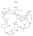
- Fig. 7 is a system diagram showing a fifth embodiment of a concentration device of the present invention.
- the present embodiment feeds at least one type of rare gas KG selected from helium, neon and argon into a mixed gas containing oxygen formed in ozone photodissociation unit 113, non-dissociated ozone and rare gas from line 131 before feeding into oxygen isotope concentration unit 114.
- Krypton RG from rare gas feed line 117 is recycled and fed thereinto, as in the third embodiment
- oxygen generated by dissociation of ozone, non-dissociated ozone, krypton RG circulating within the system, and this rare gas KG composed of at least one type selected from helium, neon and argon can be fed into oxygen isotope concentration unit 114 in a mixed state.
- At least one type of rare gas KG selected from helium, neon and argon is separated into high boiling point ozone and krypton by a separation procedure such as low-temperature distillation in oxygen isotope concentration unit 114, and discharged with oxygen OC1 having a lower boiling point.
- line for feeding at least one type of rare gas selected from helium, neon and argon may be provided in a stage before second oxygen isotope concentration unit 122. This is similar to the fourth embodiment shown in Fig. 6 .
- the peroxide used for the raw material is a substance that has an "O-O" bond its molecule, and is any of the various organic peroxides represented by the chemical formulas shown in Table 3, nitrous ester such as ONOCH 3 , or nitrate ester such as ON 2 OCH 3 .
- R and R' respectively represent a hydrogen atom or alkyl group, and R and R' may be the same or different.
- Table 5 Substance cm -1 ⁇ m NN-O 13960 0.716 ON-OCH 3 12731 0.785 ON-OC 2 H 5 13183 0.759 ON-OC 3 H 7 13183 0.759 O 2 N-OCH 13433 0.744 O 2 N-OC 2 H 5 12731 0.785 O 2 N-OC 3 H 7 13082 0.764 (CH 3 ) 3 CO-OH 13676 0.731 C 2 H 5 O-OC 2 H 5 11051 0.905 (CH 3 ) 3 CO-OC(CH 3 ) 3 12957 0.772 CH 3 COO-OCOCH 3 10315 0.969 C 2 H 5 COO-OCOC 2 H 5 10533 0.949 C 3 H 7 COO-OCOC 3 H 7 10533 0.949 C 6
- these compounds are able to undergo early dissociation by absorbing light within the range of visible light to near infrared light.
- semiconductor lasers that radiate at a wavelength in the visible to near infrared bands can be used as a light source, examples of which include InGaAsP, AlGaInP, GaAsSb, CdZnTe, CdZnSe, AlGaN and InGaN semiconductor lasers.
- the wavelength required for dissociation of this bond can be seen to be 0.9-1.0 ⁇ m.
- peracids and peroxyacids having a -COO-O- bond in their molecules are preferably used in the present invention due to the low toxicity of the raw material, reaction products and so forth, and acetic peracid (CH 3 COOOH)is particularly preferable.
- acetic peracid CH 3 COOOH
- reaction formulas (1b) through (1d) since large amounts of radicals "RO ⁇ " and “ROO ⁇ " are formed, it is preferable to suppress these reactions by diluting the peroxide with solubilizing solvent such as at least one type of solvent selected from carbon tetrachloride, acetone, acetic acid, hexane, toluene and chlorofluorocarbons.
- solubilizing solvent such as at least one type of solvent selected from carbon tetrachloride, acetone, acetic acid, hexane, toluene and chlorofluorocarbons.
- reaction formula (3b) is an exothermic reaction that is considered to have a high reaction probability.
- peracids and peroxy acids are easily dissociated by heat at high concentrations and spontaneous degrade explosively in certain cases, it is preferable to dilute with a solvent as previously described to suppress radical reactions.
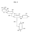
- Fig. 8 is a system diagram showing an example of the configuration of a device for carrying out the oxygen isotope concentration method of the present invention.
- This oxygen isotope concentration device is provided with a purifier 211, which removes impurities by purifying raw material vapor in which peroxide is diluted with solvent, a photoreaction cell 212, which radiates light of a specific wavelength onto the raw material vapor following purification, a cold trap 213, which captures vapor for which the photodissociation reaction in said photoreaction cell 212 has been completed by condensing or solidifying on a metal surface cooled to a low temperature, a vacuum pump 214 for reducing the pressure inside the aforementioned photoreaction cell 212 to a low pressure such as a pressure of 13 kPa or less, and a distiller 215 for separating each component captured in the aforementioned cold trap 213.
- a purifier 211 which removes impurities by purifying raw material vapor in which peroxide is diluted with solvent
- Peroxide serving as the raw material is diluted to a suitable concentration with a solvent followed by vaporization and being fed into purifier 211 from line 221.
- this purifier 211 raw material peroxide, from which impurities and water, for example, have been removed, in this purifier 211 is fed into photoreaction cell 212 through line 222.
- the peroxide undergoes the reactions of reaction formulas (1b) through (1d) accompanying dissociation of a specific bond in its molecule, for example, the RO-OH bond in hydroperoxide (ROOH) containing 17 O-H as shown in the aforementioned reaction formula (1a). In this reaction, 17 O is concentrated in water molecules.
- ROOH hydroperoxide
- Vapor containing water molecules in which 17 O is concentrated are fed from photoreaction cell 212 to cold trap 213 through line 223.
- This cold trap 213 is cooled by a chiller unit and so forth to a temperature (e.g. , -20 to -5°C) that makes it possible for a metal surface to capture the aforementioned water molecules. Since each of the components that condense or solidify at this temperature are captured on the metal surface of the chiller unit, gas such as oxygen that does condense or solidify passes through this cold trap 213 and is discharged from vacuum pump 214 after passing through line 224.
- path 225 between cold trap 213 and distiller 215 is closed by a valve and so forth.
- the following indicates the case of concentrating 17 O in water molecules by dissociating the (CH 3 ) 3 CO- 17 OH bond in the molecules using (CH 3 ) 3 COOH (tertial-butyl hydroperoxide), which is a type of hydroperoxide ROOH, for the peroxide that contains 17 O.
- the wavelength of the radiated laser light is 0.731 ⁇ m or less from the aforementioned Table 5. Since this wavelength band is the wavelength range that allows the use of an InGaAsP semiconductor laser, by precisely matching to the wavelength capable of dissociating 17 O, a specific (CH 3 ) 3 COOH containing 17 O can be dissociated according to the photodissociation reaction shown in the aforementioned reaction formula (1a).
- C 2 H 5 OOC 2 H 5 (diethyl peroxide), which is a type of dialkyl peroxide ROOR' and in which R and R' are both ethyl groups, by radiating laser light of a wavelength shorter than 0.905 ⁇ m that matches the vibration mode of the O- 17 O bond or C- 17 O bond using, for example, an InGaAsP or InGaAs semiconductor laser, it can be dissociated as shown in reaction formula (2-1a) while specifying the C 2 H 5 OOC 2 H 5 that contains the oxygen isotope 17 O.
- the radicals formed here form C 2 H 5 OH and CH 3 CHO by going through the reaction process shown in the following reaction formulas (2-1b) through (2-1d), and 17 O is concentrated in C 2 H 5 OH.
- the C 2 H 5 O ⁇ in reaction formulas (2-1b) through (2-1d) also includes radicals that contain 17 O.
- the methyl radical CH 3 ⁇ and ethyl radical C 2 H 5 ⁇ formed here are stabilized by bonding with each other.
- 17 O is concentrated in acetone or methyl ethyl ketone.
- acetic peracid in which R is a methyl group in the peroxy acid RCOOOH (and including peracids), by using a wavelength in the visible light band of 0.545-0.660 ⁇ m, which is the wavelength range over which an AlGaInP semiconductor laser can be used, that is precisely matched to the vibration mode of the 17 O-H bond, acetic peracid containing the oxygen isotope 17 O can be selectively dissociated according to the reaction formula shown in the aforementioned reaction formula (3a).
- reaction formula (3c) a list of all reactions with respect to those reactions when toluene was used as solvent results in the following reaction formula (3c), and the oxygen isotope 17 O is concentrated in molecules of water. However, although H 2 17 O is formed due to an elementary reaction with solvent, the product relating to this solvent is ignored in reaction formula (3c).
- y 1 , y 2 , y 3 and y 4 are about 0.5, 0.4, 0.1 and 0.05, respectively, while y 5 and y 6 are trace amounts.
- those substances having a double bond such as ethylene can be used as radical capturers.
- the oxygen isotopes 17 O and 18 O concentrated by the method of the present invention can be used as tracers in the fields of chemistry and medicine.
Landscapes
- Life Sciences & Earth Sciences (AREA)
- Biophysics (AREA)
- Chemical & Material Sciences (AREA)
- Chemical Kinetics & Catalysis (AREA)
- Oxygen, Ozone, And Oxides In General (AREA)
- Separation By Low-Temperature Treatments (AREA)
- Medicines Containing Material From Animals Or Micro-Organisms (AREA)
Applications Claiming Priority (4)
| Application Number | Priority Date | Filing Date | Title |
|---|---|---|---|
| JP2003057439A JP4364529B2 (ja) | 2003-03-04 | 2003-03-04 | 酸素同位体の濃縮方法及び装置 |
| JP2003200951A JP4406228B2 (ja) | 2003-07-24 | 2003-07-24 | 酸素同位体の濃縮方法及び装置 |
| JP2003319729A JP4409237B2 (ja) | 2003-09-11 | 2003-09-11 | 酸素同位体の濃縮方法 |
| EP04716324A EP1604729B1 (de) | 2003-03-04 | 2004-03-02 | Verfahren zur sauerstoffisotopkonzentration |
Related Parent Applications (1)
| Application Number | Title | Priority Date | Filing Date |
|---|---|---|---|
| EP04716324A Division EP1604729B1 (de) | 2003-03-04 | 2004-03-02 | Verfahren zur sauerstoffisotopkonzentration |
Publications (2)
| Publication Number | Publication Date |
|---|---|
| EP1997552A2 true EP1997552A2 (de) | 2008-12-03 |
| EP1997552A3 EP1997552A3 (de) | 2009-07-01 |
Family
ID=32966286
Family Applications (2)
| Application Number | Title | Priority Date | Filing Date |
|---|---|---|---|
| EP04716324A Expired - Lifetime EP1604729B1 (de) | 2003-03-04 | 2004-03-02 | Verfahren zur sauerstoffisotopkonzentration |
| EP08015904A Withdrawn EP1997552A3 (de) | 2003-03-04 | 2004-03-02 | Sauerstoffisotop-Konzentrationsverfahren |
Family Applications Before (1)
| Application Number | Title | Priority Date | Filing Date |
|---|---|---|---|
| EP04716324A Expired - Lifetime EP1604729B1 (de) | 2003-03-04 | 2004-03-02 | Verfahren zur sauerstoffisotopkonzentration |
Country Status (6)
| Country | Link |
|---|---|
| US (3) | US7893377B2 (de) |
| EP (2) | EP1604729B1 (de) |
| AT (1) | ATE527045T1 (de) |
| IL (2) | IL170576A (de) |
| TW (1) | TW200420338A (de) |
| WO (1) | WO2004078325A1 (de) |
Families Citing this family (9)
| Publication number | Priority date | Publication date | Assignee | Title |
|---|---|---|---|---|
| EP1604729B1 (de) * | 2003-03-04 | 2011-10-05 | Taiyo Nippon Sanso Corporation | Verfahren zur sauerstoffisotopkonzentration |
| JP4699784B2 (ja) * | 2005-03-28 | 2011-06-15 | 大陽日酸株式会社 | 酸素同位体の濃縮方法及び濃縮装置 |
| US8337802B2 (en) | 2005-08-17 | 2012-12-25 | Taiyo Nippon Sanso Corporation | Method for concentrating oxygen isotope or isotopes |
| JP5116274B2 (ja) * | 2006-09-26 | 2013-01-09 | 大陽日酸株式会社 | 酸素同位体重成分の濃縮方法および濃縮装置 |
| US20090173619A1 (en) * | 2008-01-09 | 2009-07-09 | General Atomics, A California Corporation | Apparatus and method for selectively dissociating molecules |
| US8758572B2 (en) * | 2011-04-20 | 2014-06-24 | Exelon Generation Company, Llc | Method for the separation and concentration of isotopologues |
| KR101329082B1 (ko) | 2011-11-25 | 2013-11-14 | 한국원자력연구원 | 광섬유 레이저를 이용한 탄소 및 산소 동위원소 분리 방법 및 장치 |
| EP3391956B1 (de) * | 2015-12-17 | 2023-07-26 | Riken | Vorrichtung und verfahren zur selektiven ionisierung von palladiumisotopen |
| US11286161B2 (en) | 2018-11-16 | 2022-03-29 | Korea Atomic Energy Research Institute | Process for isolating 170 isotope from water and process for concentrating 170 isotope using the same |
Citations (2)
| Publication number | Priority date | Publication date | Assignee | Title |
|---|---|---|---|---|
| JP2003057439A (ja) | 2001-08-09 | 2003-02-26 | Toray Ind Inc | 光学フィルムおよびその製造方法 |
| EP1604729A1 (de) | 2003-03-04 | 2005-12-14 | Taiyo Nippon Sanso Corporation | Verfahren zur sauerstoffisotopkonzentration |
Family Cites Families (31)
| Publication number | Priority date | Publication date | Assignee | Title |
|---|---|---|---|---|
| US3400024A (en) | 1955-09-15 | 1968-09-03 | Air Reduction | Inhibiting ozone decomposition with sf6, ccl2f2 or cf4 |
| US3309300A (en) | 1963-08-21 | 1967-03-14 | Welsbach Corp | Method for the production of ozone using a plasma jet |
| CH428671A (fr) * | 1964-12-02 | 1967-01-31 | Raffinage Cie Francaise | Procédé pour modifier le rapport des isotopes dans l'oxygène en faveur des isotopes lourds et installation pour la mise en oeuvre de ce procédé |
| US3622481A (en) * | 1969-11-04 | 1971-11-23 | Atomic Energy Commission | Method of producing compounds enriched in oxygen-18 |
| US3622480A (en) * | 1969-11-04 | 1971-11-23 | Atomic Energy Commission | Method of increasing the concentration of oyxgen-18 in an oxygen-containing compound |
| US3983020A (en) * | 1973-01-26 | 1976-09-28 | The Regents Of The University Of California | Isotopic separation by photopredissociation |
| US3937956A (en) | 1973-10-23 | 1976-02-10 | Exxon Research & Engineering Company | Isotope separation process |
| US4061921A (en) * | 1974-05-02 | 1977-12-06 | The United States Of America As Represented By The United States Energy Research & Development Administration | Infrared laser system |
| GB1509581A (en) * | 1974-07-31 | 1978-05-04 | Commissariat Energie Atomique | Method of eliminating radioactivity from air containing radioactive rare gases |
| US4031397A (en) * | 1975-08-25 | 1977-06-21 | Massachusetts Institute Of Technology | Method and apparatus for separating isotopes |
| US4212717A (en) * | 1975-12-22 | 1980-07-15 | The Regents Of The University Of California | Separation of isotopes by photo-induced predissociation |
| US4105921A (en) * | 1976-09-28 | 1978-08-08 | The United States Of America As Represented By The United States Department Of Energy | Isotope separation |
| US4029558A (en) | 1976-10-22 | 1977-06-14 | The United States Of America As Represented By The United States Energy Research And Development Administration | Isotope enrichment by frequency-tripled temperature tuned neodymium laser photolysis of formaldehyde |
| US4437958A (en) | 1978-01-11 | 1984-03-20 | The United States Of America As Represented By The United States Department Of Energy | Device and method for separating oxygen isotopes |
| US4436715A (en) * | 1981-09-14 | 1984-03-13 | Kms Fusion, Inc. | Storage and retrieval of singlet oxygen |
| US4801365A (en) * | 1984-11-13 | 1989-01-31 | The United States Of American As Represented By The United States Department Of Energy | Method for enriching a middle isotope using vibration-vibration pumping |
| US5174873A (en) * | 1986-02-05 | 1992-12-29 | Illinois State University | Method of isotope enrichment |
| FR2610320A1 (fr) * | 1987-02-03 | 1988-08-05 | Atochem | Composes peroxydes renfermant l'isotope 17o |
| JPH06102134B2 (ja) | 1989-08-30 | 1994-12-14 | 理化学研究所 | レーザーによる酸素18の濃縮法 |
| JPH04300633A (ja) | 1991-03-28 | 1992-10-23 | Nisshinbo Ind Inc | 炭素13のレーザー濃縮法 |
| JPH07148419A (ja) | 1993-11-29 | 1995-06-13 | Tomoshi Kitamoto | 酸素同位体の濃縮方法 |
| RU2092234C1 (ru) | 1994-09-28 | 1997-10-10 | Российский научный центр "Курчатовский институт" | Способ разделения изотопов кислорода |
| WO2000027509A1 (en) * | 1998-11-09 | 2000-05-18 | Nippon Sanso Corporation | Method and apparatus for enrichment of heavy component of oxygen isotopes |
| JP4327287B2 (ja) | 1999-01-29 | 2009-09-09 | 大陽日酸株式会社 | 重酸素水の製造方法および装置 |
| JP4495279B2 (ja) | 1999-10-12 | 2010-06-30 | 大陽日酸株式会社 | 蒸留装置並びに酸素同位体重成分の濃縮方法および重酸素水の製造方法 |
| JP3891773B2 (ja) | 2000-10-20 | 2007-03-14 | 大陽日酸株式会社 | ガスの分離精製方法及びその装置 |
| JP3505503B2 (ja) | 2000-11-22 | 2004-03-08 | 康一 浅野 | 分離係数が1に近い混合物の蒸留による分離濃縮方法および装置 |
| JP2004105889A (ja) | 2002-09-20 | 2004-04-08 | Hitachi Ltd | 酸素同位体濃縮方法及び水製造方法並びに水製造装置 |
| JP4406228B2 (ja) | 2003-07-24 | 2010-01-27 | 大陽日酸株式会社 | 酸素同位体の濃縮方法及び装置 |
| JP4364529B2 (ja) | 2003-03-04 | 2009-11-18 | 大陽日酸株式会社 | 酸素同位体の濃縮方法及び装置 |
| JP5116274B2 (ja) * | 2006-09-26 | 2013-01-09 | 大陽日酸株式会社 | 酸素同位体重成分の濃縮方法および濃縮装置 |
-
2004
- 2004-03-02 EP EP04716324A patent/EP1604729B1/de not_active Expired - Lifetime
- 2004-03-02 WO PCT/JP2004/002568 patent/WO2004078325A1/ja not_active Ceased
- 2004-03-02 EP EP08015904A patent/EP1997552A3/de not_active Withdrawn
- 2004-03-02 AT AT04716324T patent/ATE527045T1/de not_active IP Right Cessation
- 2004-03-02 US US10/547,425 patent/US7893377B2/en not_active Expired - Fee Related
- 2004-03-03 TW TW093105492A patent/TW200420338A/zh unknown
-
2005
- 2005-08-30 IL IL170576A patent/IL170576A/en not_active IP Right Cessation
-
2008
- 2008-12-04 IL IL195704A patent/IL195704A/en not_active IP Right Cessation
-
2010
- 2010-12-30 US US12/929,097 patent/US20110094874A1/en not_active Abandoned
- 2010-12-30 US US12/929,098 patent/US20110094873A1/en not_active Abandoned
Patent Citations (2)
| Publication number | Priority date | Publication date | Assignee | Title |
|---|---|---|---|---|
| JP2003057439A (ja) | 2001-08-09 | 2003-02-26 | Toray Ind Inc | 光学フィルムおよびその製造方法 |
| EP1604729A1 (de) | 2003-03-04 | 2005-12-14 | Taiyo Nippon Sanso Corporation | Verfahren zur sauerstoffisotopkonzentration |
Non-Patent Citations (2)
| Title |
|---|
| "The Chemical Record", 20 June 1975, THE CHEMICAL SOCIETY OF JAPAN, pages: 978 |
| JOURNAL OF CHEMICAL PHYSICS, vol. 108, no. 13, pages 5449 - 5475 |
Also Published As
| Publication number | Publication date |
|---|---|
| EP1604729A4 (de) | 2007-03-14 |
| US20060249366A1 (en) | 2006-11-09 |
| ATE527045T1 (de) | 2011-10-15 |
| US20110094874A1 (en) | 2011-04-28 |
| EP1997552A3 (de) | 2009-07-01 |
| US20110094873A1 (en) | 2011-04-28 |
| IL195704A (en) | 2011-04-28 |
| TW200420338A (en) | 2004-10-16 |
| EP1604729A1 (de) | 2005-12-14 |
| WO2004078325A1 (ja) | 2004-09-16 |
| EP1604729B1 (de) | 2011-10-05 |
| US7893377B2 (en) | 2011-02-22 |
| IL170576A (en) | 2011-02-28 |
Similar Documents
| Publication | Publication Date | Title |
|---|---|---|
| US20110094873A1 (en) | Oxygen isotope concentration method | |
| EP2070582B1 (de) | Verfahren und vorrichtung zur anreicherung von schweren sauerstoffisotopen | |
| CN100396364C (zh) | 氧同位素浓缩方法 | |
| EP1867383B1 (de) | Verfahren zur konzentration eines sauerstoffisotops und konzentrationsvorrichtung | |
| WO2022138162A1 (ja) | 安定同位体濃縮装置および安定同位体濃縮方法 | |
| JP4406228B2 (ja) | 酸素同位体の濃縮方法及び装置 | |
| US3904500A (en) | Hydrogen isotope separation from water | |
| RU2329093C2 (ru) | Способ концентрирования изотопа кислорода | |
| EP1923126B1 (de) | Verfahren zum aufkonzentrieren von sauerstoffisotopen | |
| JP4409237B2 (ja) | 酸素同位体の濃縮方法 | |
| JP5415105B2 (ja) | 酸素同位体の濃縮装置および濃縮方法 | |
| JP3360165B2 (ja) | 同一作業物質を用いた複数の同位体の効率的なレーザー同位体分離・濃縮法 | |
| US7307233B2 (en) | Isotope separation method and working substance for isotope separation | |
| JPH1179734A (ja) | ホスゲンの除去によって三塩化ホウ素を精製するための装置および方法 | |
| JP2024024989A (ja) | 酸素同位体の濃縮装置、及び酸素同位体の濃縮方法 | |
| SU1621996A1 (ru) | Способ фотохимического разделени изотопов ртути | |
| Kaldor et al. | Isotope separation process | |
| JPH0331489B2 (de) | ||
| JPH0871374A (ja) | 炭素同位体の分離方法 | |
| JPH05317653A (ja) | レーザーを用いた同位体の分離、濃縮方法 |
Legal Events
| Date | Code | Title | Description |
|---|---|---|---|
| PUAI | Public reference made under article 153(3) epc to a published international application that has entered the european phase |
Free format text: ORIGINAL CODE: 0009012 |
|
| AC | Divisional application: reference to earlier application |
Ref document number: 1604729 Country of ref document: EP Kind code of ref document: P |
|
| AK | Designated contracting states |
Kind code of ref document: A2 Designated state(s): AT BE BG CH CY CZ DE DK EE ES FI FR GB GR HU IE IT LI LU MC NL PL PT RO SE SI SK TR |
|
| PUAL | Search report despatched |
Free format text: ORIGINAL CODE: 0009013 |
|
| AK | Designated contracting states |
Kind code of ref document: A3 Designated state(s): AT BE BG CH CY CZ DE DK EE ES FI FR GB GR HU IE IT LI LU MC NL PL PT RO SE SI SK TR |
|
| 17P | Request for examination filed |
Effective date: 20090811 |
|
| AKX | Designation fees paid |
Designated state(s): AT BE BG CH CY CZ DE DK EE ES FI FR GB GR HU IE IT LI LU MC NL PL PT RO SE SI SK TR |
|
| 17Q | First examination report despatched |
Effective date: 20120709 |
|
| GRAP | Despatch of communication of intention to grant a patent |
Free format text: ORIGINAL CODE: EPIDOSNIGR1 |
|
| INTG | Intention to grant announced |
Effective date: 20150422 |
|
| STAA | Information on the status of an ep patent application or granted ep patent |
Free format text: STATUS: THE APPLICATION IS DEEMED TO BE WITHDRAWN |
|
| 18D | Application deemed to be withdrawn |
Effective date: 20150903 |