EP1997590A1 - Appareil de pose manuel doté d'un raccordement pour un dispositif de positionnement - Google Patents
Appareil de pose manuel doté d'un raccordement pour un dispositif de positionnement Download PDFInfo
- Publication number
- EP1997590A1 EP1997590A1 EP08103891A EP08103891A EP1997590A1 EP 1997590 A1 EP1997590 A1 EP 1997590A1 EP 08103891 A EP08103891 A EP 08103891A EP 08103891 A EP08103891 A EP 08103891A EP 1997590 A1 EP1997590 A1 EP 1997590A1
- Authority
- EP
- European Patent Office
- Prior art keywords
- switching element
- channels
- setting tool
- setting
- tool according
- Prior art date
- Legal status (The legal status is an assumption and is not a legal conclusion. Google has not performed a legal analysis and makes no representation as to the accuracy of the status listed.)
- Granted
Links
Images


Classifications
-
- B—PERFORMING OPERATIONS; TRANSPORTING
- B25—HAND TOOLS; PORTABLE POWER-DRIVEN TOOLS; MANIPULATORS
- B25C—HAND-HELD NAILING OR STAPLING TOOLS; MANUALLY OPERATED PORTABLE STAPLING TOOLS
- B25C1/00—Hand-held nailing tools; Nail feeding devices
- B25C1/008—Safety devices
Definitions
- the present invention relates to a hand-held setting tool with connection for a positioning device with tripping mediation mentioned in the preamble of claim 1.
- Art Such setting devices with connection for a positioning device with tripping or remote triggering z. B. used in overhead mounting on high ceilings, where otherwise only working with work platforms or ladders would be possible.
- the setting devices can, for. B. with solid, gaseous or liquid fuels or with compressed or compressed air or electrically operated.
- a positioning and release device for a combustion-powered setting tools which has a connection means for a setting device, which is arranged at one end of an elongate handle in the form of a rod or a rod.
- the rod is axially displaceable relative to the attachment means to actuate the trigger switch of a setting device fixed to the attachment means via coupling means.
- the positioning and triggering device further comprises a safety device which prevents triggering of the setting device in alignment with the mouth exactly in the direction of the gravitational force.
- the safety device includes for this purpose designed as a ball locking element, which is guided in a direction obliquely to the longitudinal axis of the rod and formed as a channel recess in a component in the form of the connecting means.
- the ball rolls in an orientation in the direction of the gravitational force in the path of movement of the rod and prevents further movement of the rod relative to the carrier and thus the triggering of a carrier arranged on the setting device.
- the rod has at its end facing the attachment means a radially circumferential further recess into which the ball can engage.
- a disadvantage of this setting tool is that the diameter of the ball defines the maximum, available in the release position of the ball movement path of the handle relative to the housing, within which all the necessary functions such. As the triggering of the ignition must be done. It therefore requires a high contact pressure for this short movement. It is also disadvantageous that very different angles arise when lifting the setting device up to the activation and lowering of the setting device to the renewed locking of the setting device. In other words, the limit angle at which a setting process is still possible in the case of a deviation of the setting device from a vertical orientation opposite to that of the gravitational force may differ depending on which orientation changes the setting device has undergone prior to triggering. In addition, if the setting device is pressed with momentum horizontally against the wall or down against the ground, the locking ball from its locked position roll and the setting device can be released unintentionally.
- the object of the present invention is to develop a hand-held setting tool with connection for a positioning device with tripping mediation of the aforementioned type, which avoids the disadvantages mentioned and in which theROCperperr nails allows the triggering of a setting operation by remote triggering within a predetermined angular range and a sufficient switching stroke allows to operate the setting device at the same time with little effort.
- a hand-held setting tool with connection for a positioning device having the features of the independent claim.
- a recess for the blocking element which is open toward the component along the axis is arranged on the first axis-displaceable switching element and are furthermore provided at least three each guided in a separate channel locking elements provided.
- the channels are inclined relative to a plane which intersects the axis perpendicularly, wherein the channels intersect in regions an axial projection of the first switching element and are open in the overlap regions to the first switching element.
- the channels run to the axial projection of the switching element similar to a secant, ie they do not run on the axis of the switching element, but they cut the axial projection peripherally.
- the locking position of the safety device is not only in a particular orientation of the setting device, but rotationally symmetrical to the longitudinal axis in other deviating from the approved orientation tilting plies, since then always at least one blocking element in the overlap region of a channel with the Switching element is located and thus extends into the recess. So z. B. the locking position are always triggered when the positioning device in a tilted position to the vertical (i.e., the vector of the gravitational force opposite orientation) is transferred, which exceeds a maximum allowable tilt angle.
- the maximum stroke of the switching element is not determined by the size of the blocking elements.
- the controlled via the Anpressweg functions such.
- the triggering of the setting device or the transport of cartridges in the case of powder-driven setting tools therefore, can be designed on the basis of the optimal force-displacement behavior. High contact forces can therefore be avoided.
- the setting device can be triggered when the setting device is arranged with the positioning device arranged thereon in an orientation in the direction of the vector of the gravitational force and / or a tilting position to this orientation.
- the channels are distributed rotationally symmetrically about the axis around, so that the blocking function in each rotational position of the device around its longitudinal axis always at the same release angles allows a triggering mediation.
- the locking elements are pin-shaped, whereby an early opening of the locking position can be prevented when the setting device is dynamically moved against a wall or a floor and the locking elements tend due to the accelerations occurring in the channels tend to move out of their blocking positions, as the pin-shaped blocking elements as opposed to spherical Locking elements are blocking effective over its entire axial length. Early opening of the blocking position is thus avoided.
- the switching element is rod-shaped and guided in a guide channel of the component.
- the channels are inclined at an angle between 20 ° and 50 ° to the axis perpendicularly intersecting plane.
- a reliable unlocking is achieved inclined in a vertical orientation against the gravitational force or slightly inclined to this orientation and on the other hand, the tripping switch is reliably locked in an orientation perpendicular to the vector of gravitational force (horizontal orientation) or a dynamic pressing in the direction of gravitational force.
- the overlapping areas of the channels for axial projection of the switching element towards the axis have a depth which is smaller than the diameter of the channels.
- the recess is formed as in both axial directions of the switching element closed, circumferential annular groove, whereby a good accessibility of the recess for the locking elements is achieved and the locking elements upon transfer of the device in a not authorized for a triggering orientation of the Device can easily engage from the channels into the recess blocking effective.
- FIGS. 1 to 5 an inventive hand-held setting tool 10 and a positioning device 20 is shown with tripping mediation for setting tool 10, which is for example modular.
- Such positioning devices 20 are used to extend setting devices to z. B. work overhead on ceilings etc. with the setting tool to perform.
- the positioning device 20 according to FIG. 1 a rod-like handle 21, which is connectable via a coupling element 28 with a counter-coupling element 18 at the terminal 16 of the setting tool 10.
- the connection between the coupling element 28 and the counter-coupling element 18 is detachable, so that the positioning device 20 and the setting tool 10 can be assembled and disassembled again.
- the connection between setting tool 10 and positioning device 20 on the coupling element 28 and mating coupling element 18 may, for. B. be designed as a screw or bayonet connection.
- handle 21 can still be provided one or more extension parts, between the handle 21 and the setting tool can be used and each having at one end a coupling element and at another end a counter-coupling element.
- the longitudinal extent of the rod-like handle 21 and the longitudinal extension of the setting tool 10 define an axis A.
- This in Fig. 1 reproduced setting device 10 has a arranged in a single or multi-part housing 11 setting network for driving fasteners into a structural element.
- a triggering element 13 designed as a trigger switch is arranged on the setting device 10 on a handle 12 of the setting device 10.
- the housing 11 at its end facing away from the terminal 16 upstream a total of 14 designated mouth part is arranged, which is displaceable relative to the housing 11.
- the setting device 10 is transferred to a setting ready state in which a setting process can be triggered by the trigger element 13.
- the setting device also has a switching strand, designated overall by 30, which can be brought into operative connection at the connection 16 with remote release means 40 of the positioning device 20.
- the remote release means 40 of the positioning device 20 and the switching strand 30 on setting tool 10 serve the triggering mediation of an actuating element 24 of the rod-like handle 21 to the trigger element 13 of the setting tool 10.
- the actuator 24 acts as a remote trigger switch.
- the actuating element 24 designed as an elongate actuating sleeve is guided on a supporting element 23, designed as a hollow rod, of a supporting structure.
- a supporting element 23 designed as a hollow rod, of a supporting structure.
- the z. B. on a handle portion on a coupling element 28 remote from the end of the handle 21 is arranged.
- the actuating element 24 is displaceable parallel to the axis A relative to the support element 23.
- a foot part 26 is arranged, which projects beyond a coupling element 28 remote from the axial end 27 of the actuating element 24.
- the support element 23 is fixedly connected to the coupling element 28, which has a receptacle 48 for the counter-coupling element 18 at its end remote from the support element 23.
- a Abstützstelle 45 formed for a spring element 42 which is supported with its other end of the spring via an intermediate member 43 formed as an inner sleeve on the actuating element 24 and this in the direction of his Fig. 1 apparent starting position applied elastically.
- the intermediate element 43 is fixedly connected to the actuating element 24.
- the actuating element 24 is fixedly connected to a sleeve-shaped first switching element 41 of the remote release means 40, which at least partially surrounds a portion 46 of the coupling element 28 fixed to the support element 23.
- the first switching element 41 cooperates with a second switching element 49, which is guided displaceably in a trained as a blind hole guide 44 in the coupling element 28.
- the first switching element 41 is connected via a perpendicular to the axis A extending and designed as a pin connecting means 47 to the second switching element 49.
- the connecting means 47 engages to slot-shaped openings (not visible in the figures) in the section 46 of the coupling element 28, which allow a displacement of the connecting means 47 relative to the coupling element 28 and parallel to the axis A.
- the second switching element 49 of the remote release means 40 cooperates with a trained as a pin first switching element 34 of the switching strand 30 of the setting device 10 so that a switching movement of the remote release means 40 in at least one direction along the axis A to the switching strand 30th is transferable.
- the switching strand 30 of the setting tool 10 in addition to the first switching element 34 which is movable along the axis A, also designed as a pivot lever second switching element 35, which cooperates via a formed on a first lever arm cam 36 with the first switching element 34 and at the second lever arm, a third switching element 38 is coupled.
- the third switching element 38 is designed as a shift rod and is connected to a driver 37 of the latching string 30, which cooperates with the triggering element 13 of the setting device 10.
- the setting device 10 furthermore has a safety device designated as a whole by 50 (cf. FIGS. 2 to 5 ), which triggering the on the positioning device 20th arranged setting device 10 via the control section 30 or by remote release via the actuator 24 of the positioning device 20 in a direction other than the permitted prevented.
- This safety device 50 is between a component 33 of the guide structure for the switching strand 30, which forms the leadership of the first switching element 34 at the terminal 16 in the illustrated embodiment, and relative to this axially displaceable along the axis
- a switching element of the switching string 30, in the illustrated embodiment is formed by the first switching element 34 is arranged.
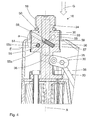
- the safety device 50 has a recess 51 formed as a radially circumferential annular groove on the outside of the first switching element 34.
- the recess 51 is open to the component 33 or radially outward.
- the recess 51 is bounded in the axial direction by groove walls 52 which extend obliquely with respect to the axis A, so that the axial width of the recess 51 decreases from radially outward to radially inward.
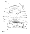
- the safety device 50 also has a plurality of, in the illustrated example exactly three, channels 56 in the component 33, which are distributed rotationally symmetrically about the axis A around (see in particular Fig. 5 ) and which are inclined with respect to a perpendicular to the axis A intersecting plane E at an angle alpha of 20 ° to 50 ° (see, in particular Figures 2 and 4 ).
- the channels 56 have a circular cross-section perpendicular to their longitudinal extent.
- a radially outer end 58 of the channels 56 is open on the lateral surface of the component 33, while a radially inner end 57 of the channels 56 is closed. Radially outside the openings of the channels 56 are closed at its radially outer end via the housing 11 (see Figures 2 and 4 ).
- the channels 56 cut in the manner of a secant partially regional an axial projection (or the guide channel) of the first switching element 34 and are open in these overlapping regions 59 to the first switching element 34.
- the length L2 of the channels 56 from the radially outer end 58 to the overlap region 59 is in each case greater than the length L1 of the channels 56 from the inner end 57 to the overlap region 59 (see FIG Fig. 2 ).
- the intersection regions 59 of the channels 56 and the axial projection of the first switching element 34 also have a depth T towards the axis A which is smaller than the diameter D of the channels 56 (see in particular FIG Fig. 3 ).
- each of the channels 56 each designed as an elongated, circular cylindrical pin locking element 55a, 55b, 55c is movably guided.
- the length L1 of the channels 56 from the inner end 57 to the overlap region 59 is smaller than the length L3 of the pin-shaped blocking elements 55a, 55b, 55c (see FIG. Fig. 2 ).
- the length L4 of the intersecting portions 59 in the longitudinal direction of the channels 56 is smaller than the length L3 of the pin-shaped blocking elements 55a, 55b, 55c.
- the pin-shaped blocking element 55a is located radially outward in the channel 56 in its radially outer end 58 facing region and is thus not blocking effective in the overlap region 59 between the portion 46 and the first switching element 34.
- the other locking elements 55b and 55c (FIG the blocking element 55c in Fig. 2 is outside the cutting plane and therefore is not visible there) are in the radially outer end 58 facing areas of the channels 56 and thus are also not blocking effective.
- the safety device 50 is in this orientation of the setting device 10 and the positioning device 20 in its triggering switching position.
- the setting device 10 on the positioning device 20 can be pressed in this orientation with the mouth part 14 to a ceiling or other workpiece and it can then be triggered by a displacement of the actuating element 24 to the coupling element 28 toward a setting process, since the locking elements 55a, 55b, 55c allow a relative movement of the first switching element 34 relative to the device 33 due to its fully engaged in the first recess 51 position.
- the first switching element 34 is thereby via the second switching element 49 (only in Fig. 1 reproduced) in the direction of the first arrow 15 or on the mouth part 14 towards the counter coupling element 18 axially offset (dashed lines shown first switching element 34 in Fig. 2 ).
- FIGS. 4 and 5 is the setting tool 10 (and in the Fig. 4 and 5 not shown positioning device 20) with the safety device 50 with his off Fig. 1 apparent mouth portion 14 by way of example aligned in the direction of the vector G of the gravitational force.
- all the pin-shaped blocking elements 55a, 55b, 55c are located in the region of the channels 56 facing the radially inner end 57 and thus due to the ratios of the lengths L3 of the pin-shaped blocking elements 55a, 55b, 55c to the lengths L1 of the radial inner ends 57 to the overlap regions 59 at least partially blocking effective in the overlapping regions 59.
- the safety device 50 is in this orientation, ie in its blocking position.
- At least one of the pin-shaped blocking elements 55a, 55b, 55c is in the blocking position and thus prevents relative movement of the first switching element 34 relative to Component 33.
- these can be conically widened at their radially inner ends 57, whereby the center axes of the pin-shaped blocking elements 55a, 55b, 55c can be inclined to the central axis of the respective channel 56.
- z. B. in a dynamic pressing of the positioning device 10 with the setting tool in the direction of the vector G of the gravitational force or extends perpendicular to this the blocking time in which at least one pin-shaped blocking element 55a, 55b, 55c at least partially blocking effective in the overlap region 59, since the pin-shaped locking element 55a, 55b, 55c must first align with the central axis of the channel 56 before it from the Overlap area 59 can disengage.
Landscapes
- Engineering & Computer Science (AREA)
- Mechanical Engineering (AREA)
- Portable Nailing Machines And Staplers (AREA)
Applications Claiming Priority (1)
| Application Number | Priority Date | Filing Date | Title |
|---|---|---|---|
| DE102007000302A DE102007000302A1 (de) | 2007-06-01 | 2007-06-01 | Handgeführtes Setzgerät mit Anschluss für eine Positioniervorrichtung |
Publications (2)
| Publication Number | Publication Date |
|---|---|
| EP1997590A1 true EP1997590A1 (fr) | 2008-12-03 |
| EP1997590B1 EP1997590B1 (fr) | 2010-02-24 |
Family
ID=39719174
Family Applications (1)
| Application Number | Title | Priority Date | Filing Date |
|---|---|---|---|
| EP08103891A Active EP1997590B1 (fr) | 2007-06-01 | 2008-05-09 | Appareil de pose manuel doté d'un raccordement pour un dispositif de positionnement |
Country Status (6)
| Country | Link |
|---|---|
| US (1) | US7914005B2 (fr) |
| EP (1) | EP1997590B1 (fr) |
| JP (1) | JP5290627B2 (fr) |
| CN (1) | CN101314219B (fr) |
| DE (2) | DE102007000302A1 (fr) |
| ES (1) | ES2340446T3 (fr) |
Families Citing this family (8)
| Publication number | Priority date | Publication date | Assignee | Title |
|---|---|---|---|---|
| DE102007000303A1 (de) * | 2007-06-01 | 2008-12-04 | Hilti Aktiengesellschaft | Positioniervorrichtung mit Auslösevermittlung für ein handgeführtes Setzgerät |
| DE102007000302A1 (de) * | 2007-06-01 | 2008-12-04 | Hilti Aktiengesellschaft | Handgeführtes Setzgerät mit Anschluss für eine Positioniervorrichtung |
| US8397968B2 (en) * | 2008-02-27 | 2013-03-19 | Black & Decker Inc. | Setting tool arrangement |
| US7896210B2 (en) | 2009-04-23 | 2011-03-01 | Illinois Tool Works Inc. | Fastener actuation system |
| US8746526B2 (en) * | 2009-09-15 | 2014-06-10 | Robert Bosch Gmbh | Fastener driver with blank fire lockout |
| US8915414B2 (en) | 2012-02-10 | 2014-12-23 | Illinois Tool Works Inc. | Combustion fastener tool with lockout mechanism |
| EP3037216A1 (fr) * | 2014-12-22 | 2016-06-29 | HILTI Aktiengesellschaft | Outil à main ainsi que dispositif comprenant cet outil à main |
| US10926389B2 (en) * | 2018-07-31 | 2021-02-23 | Chung-Heng Lee | Powder-actuated tool |
Citations (2)
| Publication number | Priority date | Publication date | Assignee | Title |
|---|---|---|---|---|
| US4479599A (en) | 1982-09-30 | 1984-10-30 | Conrad James R | Positioning and firing device for explosive-actuated tools |
| US7014085B2 (en) | 2003-07-16 | 2006-03-21 | Cetram Pty Limited | Explosively actuated tools |
Family Cites Families (18)
| Publication number | Priority date | Publication date | Assignee | Title |
|---|---|---|---|---|
| US443747A (en) * | 1890-12-30 | Albert yon derschait | ||
| US908982A (en) * | 1907-05-08 | 1909-01-05 | Frank D Ely | Firearm. |
| US960185A (en) * | 1909-11-22 | 1910-05-31 | Moore Trigger Controller Company | Trigger-controller. |
| US953279A (en) * | 1910-02-02 | 1910-03-29 | Robert A Moore | Trigger-controller. |
| US2041661A (en) * | 1935-03-25 | 1936-05-19 | Alphonse Lavallee | Safety release mechanism for firearms |
| US2273204A (en) * | 1940-03-21 | 1942-02-17 | Herman J Kneubuehl | Safety mechanism for firearms |
| US3081998A (en) * | 1958-11-25 | 1963-03-19 | Weiss Irving | Toy gun |
| JPH0739562Y2 (ja) * | 1990-09-27 | 1995-09-13 | 一雄 柏原 | 工具スイッチの遠隔操作機構 |
| JPH079361A (ja) * | 1993-06-29 | 1995-01-13 | Makita Corp | 釘送り装置における単連切換え機構 |
| US5425488A (en) * | 1993-11-05 | 1995-06-20 | Thompson William J | Impact actuated tool for driving fasteners |
| US6785996B2 (en) * | 2001-05-24 | 2004-09-07 | R.A. Brands, Llc | Firearm orientation and drop sensor system |
| US7213359B2 (en) * | 2002-03-26 | 2007-05-08 | Fabbrica D'armi Pietro Beretta S.P.A | Additional safety device for sear mechanism for firearms |
| DE10346985B4 (de) * | 2003-10-09 | 2006-05-04 | Hilti Ag | Handgeführtes Setzgerät |
| DE102004010320A1 (de) * | 2004-03-03 | 2005-09-22 | Hilti Ag | Befestigungselemente-Magazin für Setzgeräte und Setzgerät mit Befestigungselemente-Magazin |
| US7258261B1 (en) * | 2005-09-02 | 2007-08-21 | Reynaldo Reyes | Nail gun extension and actuating apparatus |
| US7228917B2 (en) * | 2005-09-22 | 2007-06-12 | Illinois Tool Works Inc. | Remote trigger actuating mechanism for power tool |
| DE102006035370A1 (de) * | 2006-10-27 | 2008-04-30 | Hilti Ag | Handgeführtes Eintreibgerät |
| DE102007000302A1 (de) * | 2007-06-01 | 2008-12-04 | Hilti Aktiengesellschaft | Handgeführtes Setzgerät mit Anschluss für eine Positioniervorrichtung |
-
2007
- 2007-06-01 DE DE102007000302A patent/DE102007000302A1/de not_active Withdrawn
-
2008
- 2008-05-09 EP EP08103891A patent/EP1997590B1/fr active Active
- 2008-05-09 DE DE502008000392T patent/DE502008000392D1/de active Active
- 2008-05-09 ES ES08103891T patent/ES2340446T3/es active Active
- 2008-05-28 CN CN2008101093101A patent/CN101314219B/zh active Active
- 2008-05-29 JP JP2008140923A patent/JP5290627B2/ja active Active
- 2008-05-30 US US12/156,167 patent/US7914005B2/en active Active
Patent Citations (2)
| Publication number | Priority date | Publication date | Assignee | Title |
|---|---|---|---|---|
| US4479599A (en) | 1982-09-30 | 1984-10-30 | Conrad James R | Positioning and firing device for explosive-actuated tools |
| US7014085B2 (en) | 2003-07-16 | 2006-03-21 | Cetram Pty Limited | Explosively actuated tools |
Also Published As
| Publication number | Publication date |
|---|---|
| CN101314219A (zh) | 2008-12-03 |
| EP1997590B1 (fr) | 2010-02-24 |
| JP2008296363A (ja) | 2008-12-11 |
| DE502008000392D1 (de) | 2010-04-08 |
| US7914005B2 (en) | 2011-03-29 |
| DE102007000302A1 (de) | 2008-12-04 |
| US20080302849A1 (en) | 2008-12-11 |
| ES2340446T3 (es) | 2010-06-02 |
| CN101314219B (zh) | 2011-11-16 |
| JP5290627B2 (ja) | 2013-09-18 |
Similar Documents
| Publication | Publication Date | Title |
|---|---|---|
| EP1997590B1 (fr) | Appareil de pose manuel doté d'un raccordement pour un dispositif de positionnement | |
| EP0645127B1 (fr) | Outil à choc pour extraction d'une prothèse de hanche | |
| EP1371455B1 (fr) | Dispositif d'accouplement pour verrouiller une connexion à fiches d'un outil | |
| DE69115623T2 (de) | Schlagwerkzeug mit Klinge | |
| EP1916066B1 (fr) | Dispositif de positionnement doté d'une commutation de déclenchement pour un appareil de pose manuel | |
| EP1796559B1 (fr) | Instrument chirurgical | |
| EP1997589B1 (fr) | Dispositif de positionnement doté d'une commutation de déclenchement pour un appareil de pose manuel | |
| EP1813393B1 (fr) | Outil de scellement | |
| EP0885599B1 (fr) | Applicateur | |
| DE3038565C2 (de) | Heftapparat | |
| DE3909744C2 (de) | Seilbetätigte Schnellabschaltvorrichtung | |
| EP1886896B1 (fr) | Colonne de direction avec accés fasile et mémoire de position | |
| WO2018130599A2 (fr) | Presse à cartouche | |
| DE102011056235A1 (de) | Medizinisches Instrument | |
| DE202004015643U1 (de) | Chirurgisches Instrument | |
| DE102006000497B4 (de) | Positioniervorrichtung mit Auslösevermittlung für ein handgeführtes Setzgerät | |
| DE19749027A1 (de) | Setzgerät | |
| DE202011052256U1 (de) | Medizinisches Instrument | |
| EP3471921B1 (fr) | Cloueur a air comprime comprenant un declenchement sequentiel et par contact | |
| EP4054447B1 (fr) | Instrument médical à tige coulissante | |
| EP1888280B1 (fr) | Liaison entre deux parties d'outil | |
| DE10346985B4 (de) | Handgeführtes Setzgerät | |
| EP2904977B1 (fr) | Instrument chirurgical et poignée pour celui-ci | |
| DE102006035410B4 (de) | Positioniervorrichtung mit Auslösevermittlung für ein handgeführtes Setzgerät | |
| EP3163139A1 (fr) | Système de vannes |
Legal Events
| Date | Code | Title | Description |
|---|---|---|---|
| PUAI | Public reference made under article 153(3) epc to a published international application that has entered the european phase |
Free format text: ORIGINAL CODE: 0009012 |
|
| AK | Designated contracting states |
Kind code of ref document: A1 Designated state(s): AT BE BG CH CY CZ DE DK EE ES FI FR GB GR HR HU IE IS IT LI LT LU LV MC MT NL NO PL PT RO SE SI SK TR |
|
| AX | Request for extension of the european patent |
Extension state: AL BA MK RS |
|
| 17P | Request for examination filed |
Effective date: 20090603 |
|
| AKX | Designation fees paid |
Designated state(s): DE ES FR GB SE |
|
| GRAP | Despatch of communication of intention to grant a patent |
Free format text: ORIGINAL CODE: EPIDOSNIGR1 |
|
| GRAS | Grant fee paid |
Free format text: ORIGINAL CODE: EPIDOSNIGR3 |
|
| GRAA | (expected) grant |
Free format text: ORIGINAL CODE: 0009210 |
|
| AK | Designated contracting states |
Kind code of ref document: B1 Designated state(s): DE ES FR GB SE |
|
| REG | Reference to a national code |
Ref country code: GB Ref legal event code: FG4D Free format text: NOT ENGLISH |
|
| REF | Corresponds to: |
Ref document number: 502008000392 Country of ref document: DE Date of ref document: 20100408 Kind code of ref document: P |
|
| REG | Reference to a national code |
Ref country code: ES Ref legal event code: FG2A Ref document number: 2340446 Country of ref document: ES Kind code of ref document: T3 |
|
| REG | Reference to a national code |
Ref country code: SE Ref legal event code: TRGR |
|
| PLBE | No opposition filed within time limit |
Free format text: ORIGINAL CODE: 0009261 |
|
| STAA | Information on the status of an ep patent application or granted ep patent |
Free format text: STATUS: NO OPPOSITION FILED WITHIN TIME LIMIT |
|
| 26N | No opposition filed |
Effective date: 20101125 |
|
| REG | Reference to a national code |
Ref country code: FR Ref legal event code: PLFP Year of fee payment: 9 |
|
| REG | Reference to a national code |
Ref country code: FR Ref legal event code: PLFP Year of fee payment: 10 |
|
| REG | Reference to a national code |
Ref country code: FR Ref legal event code: PLFP Year of fee payment: 11 |
|
| PGFP | Annual fee paid to national office [announced via postgrant information from national office to epo] |
Ref country code: SE Payment date: 20220519 Year of fee payment: 15 |
|
| PGFP | Annual fee paid to national office [announced via postgrant information from national office to epo] |
Ref country code: ES Payment date: 20220725 Year of fee payment: 15 |
|
| REG | Reference to a national code |
Ref country code: SE Ref legal event code: EUG |
|
| PG25 | Lapsed in a contracting state [announced via postgrant information from national office to epo] |
Ref country code: SE Free format text: LAPSE BECAUSE OF NON-PAYMENT OF DUE FEES Effective date: 20230510 |
|
| REG | Reference to a national code |
Ref country code: ES Ref legal event code: FD2A Effective date: 20240627 |
|
| PG25 | Lapsed in a contracting state [announced via postgrant information from national office to epo] |
Ref country code: ES Free format text: LAPSE BECAUSE OF NON-PAYMENT OF DUE FEES Effective date: 20230510 |
|
| PG25 | Lapsed in a contracting state [announced via postgrant information from national office to epo] |
Ref country code: ES Free format text: LAPSE BECAUSE OF NON-PAYMENT OF DUE FEES Effective date: 20230510 |
|
| PGFP | Annual fee paid to national office [announced via postgrant information from national office to epo] |
Ref country code: DE Payment date: 20250521 Year of fee payment: 18 |
|
| PGFP | Annual fee paid to national office [announced via postgrant information from national office to epo] |
Ref country code: GB Payment date: 20250530 Year of fee payment: 18 |
|
| PGFP | Annual fee paid to national office [announced via postgrant information from national office to epo] |
Ref country code: FR Payment date: 20250528 Year of fee payment: 18 |