EP1997614A2 - Procédé et dispositif de laminage d'éléments essentiellement en forme de plaques sous l'effet de la chaleur et de la pression - Google Patents
Procédé et dispositif de laminage d'éléments essentiellement en forme de plaques sous l'effet de la chaleur et de la pression Download PDFInfo
- Publication number
- EP1997614A2 EP1997614A2 EP08008979A EP08008979A EP1997614A2 EP 1997614 A2 EP1997614 A2 EP 1997614A2 EP 08008979 A EP08008979 A EP 08008979A EP 08008979 A EP08008979 A EP 08008979A EP 1997614 A2 EP1997614 A2 EP 1997614A2
- Authority
- EP
- European Patent Office
- Prior art keywords
- workpieces
- level
- press
- vacuum
- laminator
- Prior art date
- Legal status (The legal status is an assumption and is not a legal conclusion. Google has not performed a legal analysis and makes no representation as to the accuracy of the status listed.)
- Granted
Links
Images


Classifications
-
- B—PERFORMING OPERATIONS; TRANSPORTING
- B30—PRESSES
- B30B—PRESSES IN GENERAL
- B30B7/00—Presses characterised by a particular arrangement of the pressing members
- B30B7/02—Presses characterised by a particular arrangement of the pressing members having several platens arranged one above the other
- B30B7/023—Feeding or discharging means
-
- B—PERFORMING OPERATIONS; TRANSPORTING
- B30—PRESSES
- B30B—PRESSES IN GENERAL
- B30B5/00—Presses characterised by the use of pressing means other than those mentioned in the preceding groups
- B30B5/02—Presses characterised by the use of pressing means other than those mentioned in the preceding groups wherein the pressing means is in the form of a flexible element, e.g. diaphragm, urged by fluid pressure
-
- B—PERFORMING OPERATIONS; TRANSPORTING
- B30—PRESSES
- B30B—PRESSES IN GENERAL
- B30B7/00—Presses characterised by a particular arrangement of the pressing members
- B30B7/02—Presses characterised by a particular arrangement of the pressing members having several platens arranged one above the other
-
- B—PERFORMING OPERATIONS; TRANSPORTING
- B32—LAYERED PRODUCTS
- B32B—LAYERED PRODUCTS, i.e. PRODUCTS BUILT-UP OF STRATA OF FLAT OR NON-FLAT, e.g. CELLULAR OR HONEYCOMB, FORM
- B32B17/00—Layered products essentially comprising sheet glass, or glass, slag, or like fibres
- B32B17/06—Layered products essentially comprising sheet glass, or glass, slag, or like fibres comprising glass as the main or only constituent of a layer, next to another layer of a specific material
- B32B17/10—Layered products essentially comprising sheet glass, or glass, slag, or like fibres comprising glass as the main or only constituent of a layer, next to another layer of a specific material of synthetic resin
- B32B17/10005—Layered products essentially comprising sheet glass, or glass, slag, or like fibres comprising glass as the main or only constituent of a layer, next to another layer of a specific material of synthetic resin laminated safety glass or glazing
- B32B17/10009—Layered products essentially comprising sheet glass, or glass, slag, or like fibres comprising glass as the main or only constituent of a layer, next to another layer of a specific material of synthetic resin laminated safety glass or glazing characterized by the number, the constitution or treatment of glass sheets
- B32B17/10036—Layered products essentially comprising sheet glass, or glass, slag, or like fibres comprising glass as the main or only constituent of a layer, next to another layer of a specific material of synthetic resin laminated safety glass or glazing characterized by the number, the constitution or treatment of glass sheets comprising two outer glass sheets
-
- B—PERFORMING OPERATIONS; TRANSPORTING
- B32—LAYERED PRODUCTS
- B32B—LAYERED PRODUCTS, i.e. PRODUCTS BUILT-UP OF STRATA OF FLAT OR NON-FLAT, e.g. CELLULAR OR HONEYCOMB, FORM
- B32B17/00—Layered products essentially comprising sheet glass, or glass, slag, or like fibres
- B32B17/06—Layered products essentially comprising sheet glass, or glass, slag, or like fibres comprising glass as the main or only constituent of a layer, next to another layer of a specific material
- B32B17/10—Layered products essentially comprising sheet glass, or glass, slag, or like fibres comprising glass as the main or only constituent of a layer, next to another layer of a specific material of synthetic resin
- B32B17/10005—Layered products essentially comprising sheet glass, or glass, slag, or like fibres comprising glass as the main or only constituent of a layer, next to another layer of a specific material of synthetic resin laminated safety glass or glazing
- B32B17/10807—Making laminated safety glass or glazing; Apparatus therefor
- B32B17/10816—Making laminated safety glass or glazing; Apparatus therefor by pressing
- B32B17/10871—Making laminated safety glass or glazing; Apparatus therefor by pressing in combination with particular heat treatment
-
- B—PERFORMING OPERATIONS; TRANSPORTING
- B32—LAYERED PRODUCTS
- B32B—LAYERED PRODUCTS, i.e. PRODUCTS BUILT-UP OF STRATA OF FLAT OR NON-FLAT, e.g. CELLULAR OR HONEYCOMB, FORM
- B32B37/00—Methods or apparatus for laminating, e.g. by curing or by ultrasonic bonding
- B32B37/0007—Methods or apparatus for laminating, e.g. by curing or by ultrasonic bonding involving treatment or provisions in order to avoid deformation or air inclusion, e.g. to improve surface quality
- B32B37/003—Methods or apparatus for laminating, e.g. by curing or by ultrasonic bonding involving treatment or provisions in order to avoid deformation or air inclusion, e.g. to improve surface quality to avoid air inclusion
-
- B—PERFORMING OPERATIONS; TRANSPORTING
- B32—LAYERED PRODUCTS
- B32B—LAYERED PRODUCTS, i.e. PRODUCTS BUILT-UP OF STRATA OF FLAT OR NON-FLAT, e.g. CELLULAR OR HONEYCOMB, FORM
- B32B37/00—Methods or apparatus for laminating, e.g. by curing or by ultrasonic bonding
- B32B37/10—Methods or apparatus for laminating, e.g. by curing or by ultrasonic bonding characterised by the pressing technique, e.g. using action of vacuum or fluid pressure
-
- B—PERFORMING OPERATIONS; TRANSPORTING
- B32—LAYERED PRODUCTS
- B32B—LAYERED PRODUCTS, i.e. PRODUCTS BUILT-UP OF STRATA OF FLAT OR NON-FLAT, e.g. CELLULAR OR HONEYCOMB, FORM
- B32B37/00—Methods or apparatus for laminating, e.g. by curing or by ultrasonic bonding
- B32B37/12—Methods or apparatus for laminating, e.g. by curing or by ultrasonic bonding characterised by using adhesives
- B32B37/1207—Heat-activated adhesive
-
- H—ELECTRICITY
- H10—SEMICONDUCTOR DEVICES; ELECTRIC SOLID-STATE DEVICES NOT OTHERWISE PROVIDED FOR
- H10F—INORGANIC SEMICONDUCTOR DEVICES SENSITIVE TO INFRARED RADIATION, LIGHT, ELECTROMAGNETIC RADIATION OF SHORTER WAVELENGTH OR CORPUSCULAR RADIATION
- H10F71/00—Manufacture or treatment of devices covered by this subclass
- H10F71/137—Batch treatment of the devices
- H10F71/1375—Apparatus for automatic interconnection of photovoltaic cells in a module
-
- B—PERFORMING OPERATIONS; TRANSPORTING
- B32—LAYERED PRODUCTS
- B32B—LAYERED PRODUCTS, i.e. PRODUCTS BUILT-UP OF STRATA OF FLAT OR NON-FLAT, e.g. CELLULAR OR HONEYCOMB, FORM
- B32B2309/00—Parameters for the laminating or treatment process; Apparatus details
- B32B2309/60—In a particular environment
- B32B2309/68—Vacuum
-
- B—PERFORMING OPERATIONS; TRANSPORTING
- B32—LAYERED PRODUCTS
- B32B—LAYERED PRODUCTS, i.e. PRODUCTS BUILT-UP OF STRATA OF FLAT OR NON-FLAT, e.g. CELLULAR OR HONEYCOMB, FORM
- B32B2457/00—Electrical equipment
- B32B2457/12—Photovoltaic modules
-
- Y—GENERAL TAGGING OF NEW TECHNOLOGICAL DEVELOPMENTS; GENERAL TAGGING OF CROSS-SECTIONAL TECHNOLOGIES SPANNING OVER SEVERAL SECTIONS OF THE IPC; TECHNICAL SUBJECTS COVERED BY FORMER USPC CROSS-REFERENCE ART COLLECTIONS [XRACs] AND DIGESTS
- Y02—TECHNOLOGIES OR APPLICATIONS FOR MITIGATION OR ADAPTATION AGAINST CLIMATE CHANGE
- Y02E—REDUCTION OF GREENHOUSE GAS [GHG] EMISSIONS, RELATED TO ENERGY GENERATION, TRANSMISSION OR DISTRIBUTION
- Y02E10/00—Energy generation through renewable energy sources
- Y02E10/50—Photovoltaic [PV] energy
Definitions
- the invention relates to a method for laminating substantially plate-shaped workpieces under pressure and heat according to the preamble of claim 1 and such a device according to the preamble of claim 13.
- the case to be laminated workpieces are multi-layered and contain at least one adhesive layer with an adhesive , which is activated by heat and cures.
- the preferred field of application of the present invention is the lamination of photovoltaic modules, in which a solar cell layer, together with its electrical contacting elements encapsulated moisture-tight and weatherproof, yet translucent is covered.
- a multi-level vacuum laminating press with several press floors is used.
- a vacuum chamber is provided, which is divided by a flexible pressing means in a product half and a pressure half.
- the product half of the vacuum chamber is provided for receiving at least one workpiece and evacuated, while the pressure half of the vacuum chamber is pressurizable.
- the flexible pressing means is configured and arranged so that it presses the workpiece directly or indirectly against a bottom of the vacuum chamber due to a generated by evacuation of the product half and / or by an additional pressurizing the pressure half pressure difference in the vacuum chamber.
- a multi-level vacuum laminating press for laminating photovoltaic modules is in the EP 1 609 597 A2 described.
- This laminating press comprises a number of heating plates, between each of which a press floor is formed.
- a sealing frame is arranged in each case, which circumscribes a vacuum chamber which can be evacuated at closed press floor by tight placing the sealing frame on the underlying heating plate.
- an elastic membrane is stretched, which divides the vacuum chamber into a product half and a pressure half and serves as a pressing means to apply the pressure required for the lamination of the photovoltaic module against the heating plate.
- the yield of electrical energy from photovoltaic modules depends directly on the area. Accordingly, the processing capacity per unit area in timed processes such as lamination directly affects the cost efficiency of manufacturing the modules. Therefore, it is advantageous to use a multi-level vacuum laminating press in which several press floors are stacked. This increases the area capacity to be processed without increasing the space requirement at the production site.
- the present invention has for its object to avoid the aforementioned disadvantages of an aforementioned device or an aforementioned method and to further increase the efficiency of the lamination process.
- the present invention is therefore distinguished by the fact that the multi-level vacuum laminating press is followed by at least one multi-layer laminator.
- a transfer device is provided for transferring the workpieces from the multi-level vacuum lamination press to the at least one multi-level laminator.
- this transfer device can be formed in that both the multi-level vacuum laminating press and the multi-level laminator are provided on each floor with a conveyor belt for feeding in and out of the workpieces, wherein the transfer of the workpieces from the multi-day vacuum lamination press in the multi-day laminator by direct transfer of conveyor belt to conveyor, so no additional intermediate transfer device is necessary.
- the multi-layer vacuum laminating press and the multi-layer laminator must be arranged directly behind one another.
- the workpieces are initially only prelaminated, that is, the workpieces are placed under vacuum to avoid blistering, applied with a contact pressure and then heated until the adhesive layers have been activated so far that the extraction completed by gaseous components or has come to a standstill by the activation of the adhesive layer, and conversely, penetration of air from the outside into the workpiece or between the layers - which would lead to the formation of air bubbles - is excluded in a ventilation of the vacuum chamber.
- the workpieces are removed from the multi-level vacuum lamination press, since further processing, ie curing of the adhesive layers, no longer has to be carried out under vacuum. Rather, this can be done by the multi-layer laminator, which applies a temperature at or above the curing temperature of the adhesive layers to the workpieces without containing vacuum chambers.
- the curing cycle may be twice as long as the working cycle of the multi-level vacuum laminating press without having to wait for the multi-level vacuum laminating press to idle.
- the multi-layer laminators are preferably designed as presses, in order to cure the adhesive layers not only under the influence of temperature, but To run under pressure and to improve the heat transfer from the heating plates to the workpieces by means of contact pressure.
- one or optionally several multi-level cooling devices may be provided for cooling the workpieces to a temperature below the softening temperature of the adhesive layers.
- These cooling devices are preferably designed as presses to cool the workpieces by means of contact pressure on cooling plates.
- Highly adhesive adhesives are used to laminate photovoltaic modules.
- the flexible pressing means in the vacuum chambers of the multi-layer vacuum lamination are designed as usual as a membrane, for example made of silicone or rubber, which are each stretched on a provided in each floor of the multi-layer vacuum laminating sealing frame are such highly adhesive Adhesives, however, problematic. Because adhesive residues on the membrane, which can make them useless or at least deteriorate the result, can hardly be removed from the membrane in a multi-layer laminating with reasonable effort.
- the prior art therefore uses release liners which are placed above and below the workpieces and prevent the adhesion of adhesive residues to heating plates and membranes of the multi-level vacuum lamination press.
- release liners again requires manual labor before and after the multi-day vacuum lamination press, so that it can hardly be integrated into a fully automatic process line with fully automatic loading and unloading of the workpieces.
- the great advantage of the present invention in this context is that it is possible to run the prelaminating in the multi-stage vacuum lamination press at such low temperatures that the adhesive layers soften but begin to soften do not liquefy to the extent that it is necessary to ensure that adhesive residues get to the membrane or the heating plate. Accordingly, can be dispensed with release films.
- Curing in accordance with the invention Downstream multi-layer laminator then takes place at curing temperature of the adhesive layers, but there is no soft elastic membrane in the multi-layer laminators, which would have to be freed of adhesive residues in order not to impair their function.
- a great advantage of the method according to the invention and the corresponding device is that the temperature control in the individual stations, ie the multi-level vacuum laminating press, the multi-layer laminator and optionally further multi-layer laminators can be done independently, so that the interaction Heating and pressure can be controlled much more individually than when the entire lamination process is performed in a single multi-stage vacuum lamination press.
- the target temperature may be much higher than the cure temperature to ensure rapid heating of the workpieces, in which case the process should be discontinued accordingly early.
- the target temperature in the multi-level vacuum laminating press can be chosen to be significantly lower than the curing temperature of the adhesive layers, so that the heating of the workpieces is slower - as far as desired - and at the same time the energy input is minimized.
- the laminating process can be improved in terms of the energy used and in terms of optimized temperature control by connecting several multi-layer laminators whose target temperatures vary from laminator to laminator, in particular increase.
- the workpieces can be backed with pressure pads or upholstery and / or the workpieces can be covered with such. It is irrelevant for their effect, whether such pressure pad or pad installed stationary in the machine or loose with the workpieces spent the process spaces.
- pressure pads or upholstery can be used, which have defined thermal conductivity properties and delay the heat transfer accordingly defined.
- the membrane clamped in a sealing frame is therefore completely eliminated; their function is additionally taken over by the circulating conveyor belts. Since the conveyor belts are configured circumferentially, a cleaning of the same from the outside of the press floors is very easy, so that therefore can be dispensed with a release film. It is even possible to convert a conventional multi-daylight press to such a type designed multi-stage vacuum lamination press by retrofitting sealing elements, in particular gaskets, to form vacuum chambers. This in particular directly on a heating plate, so that the associated conveyor belt extends over the sealing elements and thus pass through both conveyor belts of adjacent heating plates, the vacuum chamber formed.
- the heating plates are for this purpose preferably provided with recesses or depressions, so that the sealing elements do not necessarily have to have the shape of a frame and yet sufficient volume is present in the vacuum chambers.
- the upper heating plate may be provided on its underside with a recess, or the lower heating plate on its upper side, or both heating plates of a press floor may have recesses.
- the contour of the vacuum chambers can thus be incorporated into the tops and / or undersides of the heating plates, including the required seals, unless the conveyor belts themselves seal against the environment of the chambers in the heating plates.
- also attached sealing frame are possible to form the vacuum chambers and their seals.
- the upper run of the conveyor belts have different material properties than the lower run. Because the upper run of the conveyor belts are used for resting transport of the workpieces to be laminated, while the lower run at least when the conveyor belts for feeding and discharging the workpieces each perform a full turn around the hot plate, only to complete the conveyor belts and not directly to the transport Serve workpieces. Accordingly, the lower runners may be made softer and more elastic and thus optimized in their function as pressing means during lamination.
- the workpieces are first discharged from the last multi-layer laminator, then in a second step, the workpieces from the preceding multi-layer laminator or from Transfer the multi-day vacuum lamination press into the downstream multi-level laminator and then transfer new workpieces to the multi-level vacuum lamination press so that half the "empty" cycle begins at the end of the product line and moves forward to the beginning of the product line. into the multi-day vacuum laminating press.
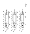
- FIG. 1 shows a schematic partial side view of three heating plates 10, 11, 12 of a multi-stage vacuum lamination with a plurality of heating plates.
- the three heating plates 10, 11, 12 shown here form two press floors between them, in each of which a workpiece 20, 21 to be laminated is located.
- a conveyor belt 30, 31, 32 to, namely to guide rollers 40, 41, 42, which in each case via a piston-cylinder unit 50, 51, 52 at the end faces of the heating plates 10, 11, 12 are fixed and by approaching these end faces, the conveyor belts 30, 31, 32 can relax and vice versa.
- the conveyor belts 30, 31, 32 each consist of a trained as a conveyor belt upper run 30a, 31 a, 32 a and a contrast elastic and wider trained lower run 30 b, 31 b, 32 b, which two parts with two releasable band connectors 60, 61, 62 (of which in this illustration, of course, only one is visible) are connected to each other.
- sealing strips 110, 111, 112 are respectively mounted between the upper runners 30a, 31a, 32a of the conveyor belts 30, 31, 32 and the upper sides of the heating plates 10, 11, 12 , while between the lower run 30b, 31b, 32b and the undersides of the heating plates 10, 11, 12 respectively upper sealing frames 80, 81, 82 are mounted, which are closed with the press ( FIG. 2 ) to the lower sealing frame 110, 111, 112 press.
- the gas-tight vacuum chambers formed thereby are each subdivided by a lower run 30b, 31b, 32b into a product half 141 and a pressure half 131, wherein the workpieces 20, 21 below the lower run 30b, 31b, 32b come to lie in the product halves 141 of the vacuum chambers ,
- the adjacent to the product halves tops of the heating plates 10, 11, 12 are configured in the present embodiment just shown and provided with only symbolically shown suction openings 100, 101, 102 to the product space between the upper run 31 a of a lower conveyor belt 31 and the lower run 30 b to be able to evacuate an upper conveyor belt 30.
- the upper runs 30a, 31a, 32a of the lower conveyor belts 30, 31, 32 are narrower than the lower run 30b, 31b, 32b, so that laterally next to the upper run 30a, 31a, 32a, a connection between the product spaces and the tops of the heating plates 10, 11, 12 are given within the sealing frame 80, 81, 82, 110, 111, 112 and the product halves 141 of the vacuum chambers are formed. Accordingly, for example, via the suction opening 102, an evacuation of the product half 141 and in particular the product space by the heating plate 12, whereby a blistering during lamination is prevented.
- the piston-cylinder units 50, 51, 52 on the end faces of the heating plates 10, 11, 12 make it possible to change the tension of the conveyor belts and thus in particular the tension of the lower run 30b, 31b, 32b.
- a high conveyor belt tension is then set when the workpieces 20, 21 are conveyed in or out, whereas when the press is closed, and in particular during the lamination process with evacuation and pressurization of the vacuum chambers, a relaxation of the conveyor belts 30, 31, 32 is advantageous: the workpieces 20, 21 then lie down due to the reduced tension of the upper run 31 a, 32 a more easily on the tops of the heating plates 11, 12, while the lower run 30 b, 31 b resist deformation by vacuum and optionally overpressure less resistance.
- a cleaning device 120, 121, 122 is also provided, for example, a rotating cleaning brush or - as shown here - a squeegee.
- the lower runways 30b, 31b, 32b of the conveyor belts 30, 31, 32 move past the cleaning devices 120, 121, 122 and are freed from any adhesive residues there.
- the lower run 30b, 31 b, 32b respectively at the top of the heating plates 10, 11, 12, so that once again a half round of the conveyor belts 30, 31, 32 is required as empty travel to a To allow retraction of other workpieces.
- the upper runways 30a, 31a, 32a of the conveyor belts 30, 31, 32 then also move past the cleaning devices 120, 121, 122, so that they too are freed from any adhesive residues.
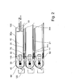
- FIG. 2 is the multi-level vacuum lamination press off FIG. 1 in similar partial representation - again only symbolically - shown, but in the closed state.
- the Untertrums 30b, 31 b, 32b of the conveyor belts 30, 31, 32 when closing the multi-layer vacuum lamination on the upper run 30a, 31a, 32a of the respective underlying conveyor belts or on the intermediate workpieces 20, 21 on.
- These vacuum chambers are gas-tightly divided by the lower run 30b, 31 b, 32 b of the conveyor belts, in an upper half of pressure 131 and a lower half product 141.
- the pressure halves 131 of the vacuum chambers via lines 90, 91, 92 subjected to compressed air.
- the teflonized, less elastic, thin lower strand 30b of a conveyor belt 30 thus takes over the function of the pressing means during prelaminating of the workpiece 20 in the present embodiment instead of an elastic membrane.
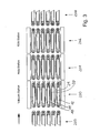
- FIG. 3 shows a schematic side view of an embodiment of an inventive device for laminating photovoltaic modules, which is divided into three stations, namely a multi-level vacuum laminating press 200, a multi-level laminator 201 and a multi-floor cooling device 202.
- a multi-level vacuum laminating press 200 Before the multi-floor Vacuum laminating press 200 and after the multi-level cooling device 202 are each multi-layered loading and unloading 203, 204 provided to promote the workpieces 20, 21 in the multi-stage vacuum lamination 200 and carefully considern from the multi-stage cooling device 202.
- Both the multi-level vacuum laminating press 200 and the multi-level laminator 201 and the multi-level cooling device 202 are formed as multi-layer presses, with the respective heating and cooling plates respectively provided with a circulating conveyor belt.
- These circulating conveyor belts form the transfer means for transferring the workpieces from the multi-level vacuum lamination press into the multi-level laminator and the multi-day refrigerating device, wherein the workpieces 20, 21 are transferred directly from one station to another without the need for a separate transfer device. Accordingly, the three stations shown are space-saving arranged directly behind one another.
- the lower run of the conveyor belts are designed differently than the upper run of the conveyor belts, half a turn of the conveyor belt is necessary as empty travel to 21 after the discharge of the workpieces to be able to feed new work again.
- the multi-level laminator 201 and in the multi-level cooling device 202 it may also be provided to perform such an empty run, for example, to clean the conveyor belts. Accordingly, at the in FIG.
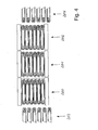
- FIG. 4 is one opposite FIG. 3 slightly different view of the same embodiment, in which case both the multi-layer vacuum laminating press 200 and the multi-layer laminator 201 and the multi-layer cooling device 202 are closed. It is therefore the representation of the working clock of the clocked operated device. It should be noted at this point that although a clocked mode of operation of the device according to the invention is preferred, it is not mandatory. It is also not necessary in the context of the present invention that all of the press floors of one of the presses are opened and closed simultaneously, but the press floors can, in principle, also be operated in groups or individually.
- the workpieces 20, 21 are applied according to the invention only in the multi-day vacuum laminating 200 with vacuum.
- the multi-level laminator 201 and the multi-level cooling device 202 are each formed as a press to improve the heat transfer to both the heating plates and on the other hand, the cooling plates by means of contact pressure. Pressurization in the multi-layer laminator 201 also assists curing of the adhesive layers in the workpieces.
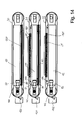
- FIGS. 5 and 6 show a completed representation of the multi-level vacuum laminating press 200 in the open ( FIG. 5 ) and closed ( FIG. 6 ) Status.
- two hydraulic cylinders 205, 206 which are each attached on one hand to an upper pressure bar 207 and a lower, movable against a frame 209 pressure bar 208, the upper and lower pressure bars 207, 208 are moved against each other so as to close the press and to open. Accordingly, in the present embodiment, all press floors are opened and closed sequentially.
- FIG. 7 shows a diagram of various boundary conditions of a conventional process in a multi-day vacuum lamination press.
- the workpieces are hereby processed until the adhesive layers have cured in the multi-level vacuum lamination press.
- the solid line 301 indicates the temperature in the workpiece
- the dotted line 302 in the first half of the diagram represents the air pressure in the product half of the vacuum chamber and in the second half as the line 303 the contact pressure acting on the workpiece, in the case of the line 302 entered directly as gas pressure in mbar and in case of line 303 equivalent to gas pressure in mbar.
- the dashed lines 304 and 305 result, with the line 304 indicating the softening of the adhesive layers in%, while the line 305 represents the degree of crosslinking of the adhesive layers, here a crosslinking adhesive.
- the temperature of the workpieces along the line 301 increases from room temperature (20 ° C.) to the target temperature (about 150 ° C.), the rise of the line 301 depending on the heat transfer between the heating plates and the workpieces ,
- the pressure half of the vacuum chamber Upon reaching a temperature of about 120 ° C and a degree of softening of about 80%, the pressure half of the vacuum chamber is vented, so that the pressing means, which separates the pressure half of the (further evacuated) half of the product vacuum chamber, exerts an increasing contact pressure on the workpiece , This is illustrated by the line 303.
- the pressure half of the vacuum chamber is merely ventilated, but not subjected to an additional pressure, so that the resulting, acting on the workpiece contact pressure (line 303) slightly below the atmospheric pressure.
- the degree of crosslinking (305) of the adhesive layers increases, so that curing takes place.
- the contact pressure of the workpiece against the heating plate caused by the aeration of the pressure half of the vacuum chamber increases the heat transfer into the workpiece, whereby the temperature (301) increases more rapidly until it approaches the target temperature in a flattening manner.
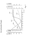
- FIG. 8 shows a first example of a process according to the invention, wherein station I symbolizes the multi-level vacuum laminating press, station II the multi-layer laminator and station III a second multi-layer laminator.
- the multi-day cooler is called Station IV in FIG FIG. 10 shown.
- the pressure in the product half of the vacuum chamber (line 302) is lowered as quickly as possible in order to prevent blistering in the adhesive layers. Since the process according to the invention is distributed over several stations, however, the target temperature does not have to be at or above the curing temperature of the adhesive layers, as in the conventional process, but can be chosen lower. In the present case, the target temperature is 120 ° C, which is illustrated by a double line 306.
- the workpiece heats up more slowly, resulting in a flatter temperature curve 301. Accordingly, the softening 304 of the adhesive layers takes place more slowly, so that the evacuation of the product space (line 302) can be completed even before the adhesive layers have appreciably softened.
- the curing of the adhesive layers then takes place stepwise in the stations II and III, ie in two successive multi-layer laminators.
- the target temperature 306 is still at a lower level than the curing temperature, in this case at about 140 ° C., so that the temperature 301 is slow, and only in the second stage in station III of the target temperature Approaches 150 ° C.
- the contact pressure acting on the workpieces can be regulated for optimal cross-linking (line 305).
- line 305 By initially only one-sided aeration of the pressure half of the vacuum chamber in station I and only then bilateral venting to open the multi-layer vacuum laminating press, by the way already in station I a certain contact pressure - line 303 - exerted on the workpiece.
- FIG. 9 A further example of the process control in the method according to the invention is shown, which corresponds to the in FIG. 8 illustrated example, but is configured differently with respect to the process parameters.
- a higher contact pressure is applied to the workpieces, while the target temperatures as in Example after FIG. 8 are selected.
- the loading of the workpieces with a contact pressure in station I to better avoid blistering during prelaminating is done here earlier and to a greater extent.
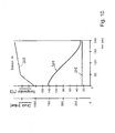
- FIG. 10 complete both FIG. 8 as well as FIG. 9 with a station IV, which symbolizes a multi-day cooling device.
- the target temperature 306 is at room temperature and the course of the workpiece temperature 301 is decreasing, from the curing temperature of nearly 150 ° C to room temperature.
- the heat transfer from the cooling plates (306) to the workpieces (301) is improved by a contact pressure 303, which is why the multi-level cooling device (station IV) is designed as a multi-day press with cooling plates.
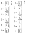
- FIGS. 11 and 12 schematically show two different embodiments of a device according to the invention, wherein in the embodiment according to FIG. 11 a multi-level vacuum laminating press 200 (vacuum station I) two multi-level laminators 201 a and 201 b (heating stations II and III) and a multi-day cooling device 202 (cooling station IV) are connected downstream.
- a charging device 203 is provided, while for discharging the multi-level cooling device 202, a discharge device 204 is connected downstream.
- FIG. 11 The production line shown in the FIGS. 8 and 10 or 9 and 10 processes shown are driven.
- FIG. 12 The production line shown here differs from this merely in that instead of a multi-level cooling device 202, two multi-level cooling devices 202a and 202b are provided, for example for adapting the working cycles to the multi-level vacuum lamination press 200 whose working cycle may be too short to cool down the to allow ready laminated workpieces in a single cooling station.
- FIG. 13a an example of a workpiece 20 is shown, which is to be laminated by the method according to the invention. It is a silicon solar cell module with a number of silicon solar cells 401 embedded between two adhesive foils 402. The front of the module is formed by a substrate glass 403, while on the back of the module, a backsheet 404 is placed. As can be seen directly from this illustration, the illustrated workpiece 20 is laminated by the method according to the invention so that the substrate glass 403, the silicon solar cells 401 and the backsheet 404 are permanently and weatherproof connected to each other due to the crosslinking adhesive contained in the adhesive films 402 ,
- FIG. 13b shows another example of a workpiece 21 to be laminated, which in turn is a photovoltaic module, but includes a thin-film solar cell 405 sandwiched between a substrate glass 403 and a back glass 406 in an adhesive film 402. After the lamination process, the substrate glass 403 and the backside glass 406 with the thin-film solar cell 405 lying between them are permanently and weatherproof.
- FIG. 14 shows how FIG. 1 , A schematic partial side view of three heating plates 10, 11, 12 of a multi-stage vacuum lamination press, which in turn form two press floors, each with a workpiece to be laminated 20, 21.
- a conveyor belt 30, 31, 32 runs around the heating plates 10, 11, 12, and in turn around deflection rollers 40, 41, 42, which in each case over a piston-cylinder unit 50, 51, 52 are fixed to the end faces of the heating plates 10, 11, 12 and by moving to these front sides, the conveyor belts 30, 31, 32 can relax and vice versa.
- a cleaning device 120, 121, 122 is arranged in each case.
- Lower sealing frames 111, 112 and upper sealing frames 80, 81 are in turn present to form the vacuum chambers in the individual levels of the multi-level vacuum laminating press shown in part. Unlike the in FIG. 1 illustrated embodiment are here on the upper sealing frame 80, 81, however, membrane 150, 151 attached, which subdivide the gas-tight vacuum chambers formed in the closed press each in a product half and a pressure half. The membranes 150, 151 thus take over the function of the lower run 30b, 31b, 32b of the embodiment in a conventional manner FIG. 1 , so that incidentally on the FIG. 1 described operation and the state of the art in vacuum laminating presses may be referenced.
- FIG. 14 is finally provided as an additional modification, between the heating plates 11,12 and the workpieces 20, 21 each a pressure pad 160, 161 to order to compensate for any bumps or tolerances in the parallelism of the workpieces 20, 21.
- FIG. 15 is another modification of the in the FIGS. 1 and 2 illustrated embodiment of a device according to the invention, wherein the modification consists in that above and below the workpieces 20, 21 each have a cushion 170, 171, 172, 173 attached, which serves not only for better pressure distribution, but also on defined heat conduction properties has and the heat transfer from the heating plates 10, 11, 12 on the workpieces 20, 21 influenced in a defined manner.
- the modification consists in that above and below the workpieces 20, 21 each have a cushion 170, 171, 172, 173 attached, which serves not only for better pressure distribution, but also on defined heat conduction properties has and the heat transfer from the heating plates 10, 11, 12 on the workpieces 20, 21 influenced in a defined manner.
Landscapes
- Engineering & Computer Science (AREA)
- Physics & Mathematics (AREA)
- Mechanical Engineering (AREA)
- Fluid Mechanics (AREA)
- Thermal Sciences (AREA)
- Quality & Reliability (AREA)
- Lining Or Joining Of Plastics Or The Like (AREA)
- Laminated Bodies (AREA)
- Photovoltaic Devices (AREA)
- Hybrid Cells (AREA)
- Casting Or Compression Moulding Of Plastics Or The Like (AREA)
Priority Applications (1)
| Application Number | Priority Date | Filing Date | Title |
|---|---|---|---|
| PL08008979T PL1997614T3 (pl) | 2007-05-30 | 2008-05-15 | Sposób i urządzenie do laminowania półwyrobów, zasadniczo w kształcie płyty, pod działaniem ciśnienia i ciepła |
Applications Claiming Priority (2)
| Application Number | Priority Date | Filing Date | Title |
|---|---|---|---|
| DE102007025380A DE102007025380A1 (de) | 2007-05-30 | 2007-05-30 | Mehretagen-Laminierpresse |
| DE102007034135A DE102007034135A1 (de) | 2007-05-30 | 2007-07-21 | Verfahren und Vorrichtung zum Laminieren von im Wesentlichen plattenförmigen Werkstücken unter Druck- und Wärmeeinwirkung |
Publications (3)
| Publication Number | Publication Date |
|---|---|
| EP1997614A2 true EP1997614A2 (fr) | 2008-12-03 |
| EP1997614A3 EP1997614A3 (fr) | 2010-09-22 |
| EP1997614B1 EP1997614B1 (fr) | 2011-07-20 |
Family
ID=39717792
Family Applications (1)
| Application Number | Title | Priority Date | Filing Date |
|---|---|---|---|
| EP08008979A Active EP1997614B1 (fr) | 2007-05-30 | 2008-05-15 | Procédé et dispositif de laminage d'éléments essentiellement en forme de plaques sous l'effet de la chaleur et de la pression |
Country Status (6)
| Country | Link |
|---|---|
| US (1) | US20080295956A1 (fr) |
| EP (1) | EP1997614B1 (fr) |
| JP (1) | JP4790759B2 (fr) |
| AT (1) | ATE516949T1 (fr) |
| DE (1) | DE102007034135A1 (fr) |
| PL (1) | PL1997614T3 (fr) |
Cited By (4)
| Publication number | Priority date | Publication date | Assignee | Title |
|---|---|---|---|---|
| EP2154216A3 (fr) * | 2008-08-15 | 2011-08-17 | Tesa Se | Procédé de collage sans bulles de matériaux hautement transparents |
| EP2448010A2 (fr) | 2010-10-30 | 2012-05-02 | Robert Bürkle GmbH | Procédé de fabrication d'un scellement de bord de modules photovoltaïques et utilisation d'un corps extrudé correspondant, et module photovoltaïque correspondant |
| DE102015115453A1 (de) | 2015-09-14 | 2017-03-16 | Robert Bürkle GmbH | Laminiervorrichtung zum Laminieren eines Schichtenstapels und Anlage zum Herstellen von Photovoltaikmodulen |
| DE102018101470A1 (de) | 2018-01-23 | 2019-07-25 | Robert Bürkle GmbH | Laminiervorrichtung und Verfahren zum Laminieren wenigstens eines Schichtenstapels |
Families Citing this family (21)
| Publication number | Priority date | Publication date | Assignee | Title |
|---|---|---|---|---|
| DE102009010351A1 (de) | 2009-02-25 | 2010-09-02 | Theodor Hymmen Holding Gmbh | Verfahren und Vorrichtung zum Verkleben von plattenförmigen und bahnförmigen Werkstoffen |
| JP2010207902A (ja) * | 2009-03-12 | 2010-09-24 | Kitagawa Elaborate Mach Co Ltd | 真空プレス装置及び真空プレス方法 |
| DE102009002023B4 (de) * | 2009-03-31 | 2013-04-04 | Hans Gerd Stevens | Laminationsvorrichtung |
| EP2239789A1 (fr) * | 2009-04-08 | 2010-10-13 | SAPHIRE ApS | Assemblage stratifié |
| JP2010278147A (ja) * | 2009-05-27 | 2010-12-09 | Kyocera Corp | 太陽電池モジュールの製造方法 |
| DE102009042148B8 (de) | 2009-09-14 | 2019-12-12 | Schmid Technology Systems Gmbh | Etagenpresse und Verfahren zur Herstellung von plattenförmigen Werkstücken |
| DE202009016044U1 (de) | 2009-11-24 | 2010-03-25 | Sagolla, Heinrich | Laminatorheizplatte eines Photovoltaik-Modul-Laminators mit gleichmäßiger Temperaturverteilung |
| GB0922226D0 (en) | 2009-12-21 | 2010-02-03 | Teknisolar Ltd | Lamination apparatus |
| JP2012051350A (ja) | 2010-09-03 | 2012-03-15 | Fuji Electric Co Ltd | ラミネート処理方法 |
| JP2012054515A (ja) | 2010-09-03 | 2012-03-15 | Fuji Electric Co Ltd | 太陽電池モジュールの製造方法 |
| US20120060758A1 (en) * | 2011-03-24 | 2012-03-15 | Primestar Solar, Inc. | Dynamic system for variable heating or cooling of linearly conveyed substrates |
| JP2013026611A (ja) * | 2011-07-26 | 2013-02-04 | Sanyo Electric Co Ltd | 太陽電池モジュールの製造方法 |
| US20130105062A1 (en) * | 2011-11-02 | 2013-05-02 | Asm Technology Singapore Pte. Ltd. | Apparatus for laminating a photovoltaic layup, and a method of laminating the same |
| DE102012005795A1 (de) * | 2012-03-14 | 2013-09-19 | Kienle + Spiess Gmbh | Lamellenpaket und Verfahren zu seiner Herstellung |
| CN102825894B (zh) * | 2012-09-20 | 2015-03-18 | 天津英利新能源有限公司 | 一种光伏组件的层压方法 |
| CN107215074A (zh) * | 2017-04-01 | 2017-09-29 | 秦皇岛可视自动化设备有限公司 | 一种新型的板状件层压机及层压板状件的方法 |
| EP3407393A1 (fr) * | 2017-05-23 | 2018-11-28 | Meyer Burger (Switzerland) AG | Ligne de production d'un module solaire |
| DE102017219516B4 (de) * | 2017-11-02 | 2025-06-26 | Audi Ag | Verfahren und Vorrichtung zur Herstellung einer Batteriewanne mit geklebter Kühlvorrichtung |
| CN113002039B (zh) * | 2020-10-28 | 2023-07-25 | 秦皇岛可视自动化设备有限公司 | 一种新型的板压式层压机及层压板状件的施压方法 |
| CN114833984A (zh) * | 2022-04-12 | 2022-08-02 | 环晟新能源(江苏)有限公司 | 一种叠瓦组件层压工艺 |
| WO2025021739A1 (fr) | 2023-07-25 | 2025-01-30 | Saint-Gobain Glass France | Procédé de production d'une vitre composite ayant un module photovoltaïque |
Citations (1)
| Publication number | Priority date | Publication date | Assignee | Title |
|---|---|---|---|---|
| EP1609597A2 (fr) | 2004-06-04 | 2005-12-28 | Meier Vakuumtechnik GmbH | Presse pour fabriquer un corps multicouche |
Family Cites Families (5)
| Publication number | Priority date | Publication date | Assignee | Title |
|---|---|---|---|---|
| DE3725007A1 (de) * | 1987-07-29 | 1989-02-09 | Matsushita Electric Works Ltd | Viel-platten-presse zum herstellen von laminaten unter unterdruck |
| AU676330B2 (en) * | 1993-06-11 | 1997-03-06 | Isovolta Osterreichische Isolierstoffwerke Aktiengesellschaft | Process and device for manufacturing photovoltaic modules |
| JP3608102B2 (ja) * | 1998-10-30 | 2005-01-05 | 株式会社名機製作所 | ラミネータおよび積層成形方法 |
| DE10227649A1 (de) * | 2002-06-20 | 2004-01-08 | Robert Bürkle GmbH | Plattenpresse |
| JP4259838B2 (ja) * | 2002-10-02 | 2009-04-30 | ニチゴー・モートン株式会社 | 積層装置及び積層方法 |
-
2007
- 2007-07-21 DE DE102007034135A patent/DE102007034135A1/de not_active Withdrawn
-
2008
- 2008-05-15 EP EP08008979A patent/EP1997614B1/fr active Active
- 2008-05-15 AT AT08008979T patent/ATE516949T1/de active
- 2008-05-15 PL PL08008979T patent/PL1997614T3/pl unknown
- 2008-05-30 US US12/129,960 patent/US20080295956A1/en not_active Abandoned
- 2008-05-30 JP JP2008143183A patent/JP4790759B2/ja active Active
Patent Citations (1)
| Publication number | Priority date | Publication date | Assignee | Title |
|---|---|---|---|---|
| EP1609597A2 (fr) | 2004-06-04 | 2005-12-28 | Meier Vakuumtechnik GmbH | Presse pour fabriquer un corps multicouche |
Cited By (6)
| Publication number | Priority date | Publication date | Assignee | Title |
|---|---|---|---|---|
| EP2154216A3 (fr) * | 2008-08-15 | 2011-08-17 | Tesa Se | Procédé de collage sans bulles de matériaux hautement transparents |
| EP2448010A2 (fr) | 2010-10-30 | 2012-05-02 | Robert Bürkle GmbH | Procédé de fabrication d'un scellement de bord de modules photovoltaïques et utilisation d'un corps extrudé correspondant, et module photovoltaïque correspondant |
| DE102015115453A1 (de) | 2015-09-14 | 2017-03-16 | Robert Bürkle GmbH | Laminiervorrichtung zum Laminieren eines Schichtenstapels und Anlage zum Herstellen von Photovoltaikmodulen |
| DE102018101470A1 (de) | 2018-01-23 | 2019-07-25 | Robert Bürkle GmbH | Laminiervorrichtung und Verfahren zum Laminieren wenigstens eines Schichtenstapels |
| WO2019145308A1 (fr) | 2018-01-23 | 2019-08-01 | Robert Bürkle GmbH | Dispositif de laminage et procédé destiné à laminer au moins un empilement de couches |
| US12528278B2 (en) | 2018-01-23 | 2026-01-20 | Robert Bürkle GmbH | Laminating device and method for laminating at least one layer stack |
Also Published As
| Publication number | Publication date |
|---|---|
| DE102007034135A1 (de) | 2009-01-29 |
| EP1997614B1 (fr) | 2011-07-20 |
| JP2008296583A (ja) | 2008-12-11 |
| JP4790759B2 (ja) | 2011-10-12 |
| PL1997614T3 (pl) | 2011-12-30 |
| EP1997614A3 (fr) | 2010-09-22 |
| ATE516949T1 (de) | 2011-08-15 |
| US20080295956A1 (en) | 2008-12-04 |
Similar Documents
| Publication | Publication Date | Title |
|---|---|---|
| EP1997614B1 (fr) | Procédé et dispositif de laminage d'éléments essentiellement en forme de plaques sous l'effet de la chaleur et de la pression | |
| EP2141018A2 (fr) | Procédé et dispositif de laminage de pièces à usiner essentiellement en forme de plaques sous l'effet de la chaleur et de la pression | |
| EP1997613B1 (fr) | Presse de lamination à plusieurs étages | |
| EP2236287B1 (fr) | Dispositif de laminage | |
| EP2457728B1 (fr) | Procédé de laminage de pièces essentiellement en forme de plaques | |
| EP1609597A2 (fr) | Presse pour fabriquer un corps multicouche | |
| EP2159047B1 (fr) | Procédé et presse de laminage destinés à laminer des pièces à usiner | |
| EP1894717B1 (fr) | Presse et procédé pour laminer à chaud et sous pression des objets en forme de plaques | |
| DE112010005538T5 (de) | Laminatpressvorrichtung, Aushärtungsvorrichtung, Trägerplatte, Laminiersystem und Laminierverfahren | |
| EP2127867B1 (fr) | Presse et procédé de laminage de pièces usinées en forme de plaque | |
| DE112010001156T5 (de) | Laminiereinrichtung und Laminierverfahren für elne Solarbatterie | |
| DE102009010351A1 (de) | Verfahren und Vorrichtung zum Verkleben von plattenförmigen und bahnförmigen Werkstoffen | |
| DE102015115453A1 (de) | Laminiervorrichtung zum Laminieren eines Schichtenstapels und Anlage zum Herstellen von Photovoltaikmodulen | |
| EP3651989B1 (fr) | Dispositif de laminage et procédé destiné à laminer au moins un empilement de couches | |
| AT508268B1 (de) | Verfahren zur herstellung eines aus schichten aufgebauten solarpaneels | |
| DE102009042148B4 (de) | 14.09.2009Etagenpresse und Verfahren zur Herstellung von plattenförmigen Werkstücken | |
| DE102009002024B4 (de) | Laminationsvorrichtung mit Dichtrahmen | |
| DE102007012496B3 (de) | Etagenpresse für Formteile | |
| DE102009019687B4 (de) | Laminationsvorrichtung und Verfahren zum Laminieren und Rahmen von Bauteilestapeln | |
| DE3725007A1 (de) | Viel-platten-presse zum herstellen von laminaten unter unterdruck | |
| AT507132A1 (de) | Laminierpresse mit prozessplatte | |
| DE102010040885B4 (de) | Auflager für eine Laminationsvorrichtung, Laminationsvorrichtung und Verfahren zum Laminieren von Bauteilstapeln | |
| EP2279855A2 (fr) | Presse et procédé pour l'alimentation et l'extraction de pièces pour la presse | |
| DE102010040886B4 (de) | Laminationsvorrichtung und Verwendung einer Folie in einer Laminationsvorrichtung | |
| AT504680B1 (de) | Verfahren und vorrichtung zum herstellen laminierter solarmodule |
Legal Events
| Date | Code | Title | Description |
|---|---|---|---|
| PUAI | Public reference made under article 153(3) epc to a published international application that has entered the european phase |
Free format text: ORIGINAL CODE: 0009012 |
|
| AK | Designated contracting states |
Kind code of ref document: A2 Designated state(s): AT BE BG CH CY CZ DE DK EE ES FI FR GB GR HR HU IE IS IT LI LT LU LV MC MT NL NO PL PT RO SE SI SK TR |
|
| AX | Request for extension of the european patent |
Extension state: AL BA MK RS |
|
| PUAL | Search report despatched |
Free format text: ORIGINAL CODE: 0009013 |
|
| AK | Designated contracting states |
Kind code of ref document: A3 Designated state(s): AT BE BG CH CY CZ DE DK EE ES FI FR GB GR HR HU IE IS IT LI LT LU LV MC MT NL NO PL PT RO SE SI SK TR |
|
| AX | Request for extension of the european patent |
Extension state: AL BA MK RS |
|
| 17P | Request for examination filed |
Effective date: 20101120 |
|
| GRAP | Despatch of communication of intention to grant a patent |
Free format text: ORIGINAL CODE: EPIDOSNIGR1 |
|
| RIC1 | Information provided on ipc code assigned before grant |
Ipc: B30B 7/02 20060101AFI20110211BHEP Ipc: B32B 37/10 20060101ALI20110211BHEP |
|
| GRAS | Grant fee paid |
Free format text: ORIGINAL CODE: EPIDOSNIGR3 |
|
| AKX | Designation fees paid |
Designated state(s): AT BE BG CH CY CZ DE DK EE ES FI FR GB GR HR HU IE IS IT LI LT LU LV MC MT NL NO PL PT RO SE SI SK TR |
|
| GRAA | (expected) grant |
Free format text: ORIGINAL CODE: 0009210 |
|
| AK | Designated contracting states |
Kind code of ref document: B1 Designated state(s): AT BE BG CH CY CZ DE DK EE ES FI FR GB GR HR HU IE IS IT LI LT LU LV MC MT NL NO PL PT RO SE SI SK TR |
|
| REG | Reference to a national code |
Ref country code: GB Ref legal event code: FG4D Free format text: NOT ENGLISH |
|
| REG | Reference to a national code |
Ref country code: CH Ref legal event code: EP |
|
| REG | Reference to a national code |
Ref country code: DE Ref legal event code: R096 Ref document number: 502008004228 Country of ref document: DE Effective date: 20110915 |
|
| REG | Reference to a national code |
Ref country code: CH Ref legal event code: NV Representative=s name: R. A. EGLI & CO. PATENTANWAELTE |
|
| REG | Reference to a national code |
Ref country code: NL Ref legal event code: VDEP Effective date: 20110720 |
|
| REG | Reference to a national code |
Ref country code: ES Ref legal event code: FG2A Ref document number: 2370070 Country of ref document: ES Kind code of ref document: T3 Effective date: 20111212 |
|
| REG | Reference to a national code |
Ref country code: PL Ref legal event code: T3 |
|
| REG | Reference to a national code |
Ref country code: GR Ref legal event code: EP Ref document number: 20110402336 Country of ref document: GR Effective date: 20111117 |
|
| PG25 | Lapsed in a contracting state [announced via postgrant information from national office to epo] |
Ref country code: LT Free format text: LAPSE BECAUSE OF FAILURE TO SUBMIT A TRANSLATION OF THE DESCRIPTION OR TO PAY THE FEE WITHIN THE PRESCRIBED TIME-LIMIT Effective date: 20110720 Ref country code: PT Free format text: LAPSE BECAUSE OF FAILURE TO SUBMIT A TRANSLATION OF THE DESCRIPTION OR TO PAY THE FEE WITHIN THE PRESCRIBED TIME-LIMIT Effective date: 20111121 Ref country code: FI Free format text: LAPSE BECAUSE OF FAILURE TO SUBMIT A TRANSLATION OF THE DESCRIPTION OR TO PAY THE FEE WITHIN THE PRESCRIBED TIME-LIMIT Effective date: 20110720 Ref country code: SE Free format text: LAPSE BECAUSE OF FAILURE TO SUBMIT A TRANSLATION OF THE DESCRIPTION OR TO PAY THE FEE WITHIN THE PRESCRIBED TIME-LIMIT Effective date: 20110720 Ref country code: HR Free format text: LAPSE BECAUSE OF FAILURE TO SUBMIT A TRANSLATION OF THE DESCRIPTION OR TO PAY THE FEE WITHIN THE PRESCRIBED TIME-LIMIT Effective date: 20110720 Ref country code: NL Free format text: LAPSE BECAUSE OF FAILURE TO SUBMIT A TRANSLATION OF THE DESCRIPTION OR TO PAY THE FEE WITHIN THE PRESCRIBED TIME-LIMIT Effective date: 20110720 Ref country code: IS Free format text: LAPSE BECAUSE OF FAILURE TO SUBMIT A TRANSLATION OF THE DESCRIPTION OR TO PAY THE FEE WITHIN THE PRESCRIBED TIME-LIMIT Effective date: 20111120 Ref country code: NO Free format text: LAPSE BECAUSE OF FAILURE TO SUBMIT A TRANSLATION OF THE DESCRIPTION OR TO PAY THE FEE WITHIN THE PRESCRIBED TIME-LIMIT Effective date: 20111020 |
|
| REG | Reference to a national code |
Ref country code: IE Ref legal event code: FD4D |
|
| PG25 | Lapsed in a contracting state [announced via postgrant information from national office to epo] |
Ref country code: LV Free format text: LAPSE BECAUSE OF FAILURE TO SUBMIT A TRANSLATION OF THE DESCRIPTION OR TO PAY THE FEE WITHIN THE PRESCRIBED TIME-LIMIT Effective date: 20110720 Ref country code: CY Free format text: LAPSE BECAUSE OF FAILURE TO SUBMIT A TRANSLATION OF THE DESCRIPTION OR TO PAY THE FEE WITHIN THE PRESCRIBED TIME-LIMIT Effective date: 20110720 Ref country code: SI Free format text: LAPSE BECAUSE OF FAILURE TO SUBMIT A TRANSLATION OF THE DESCRIPTION OR TO PAY THE FEE WITHIN THE PRESCRIBED TIME-LIMIT Effective date: 20110720 |
|
| PG25 | Lapsed in a contracting state [announced via postgrant information from national office to epo] |
Ref country code: CZ Free format text: LAPSE BECAUSE OF FAILURE TO SUBMIT A TRANSLATION OF THE DESCRIPTION OR TO PAY THE FEE WITHIN THE PRESCRIBED TIME-LIMIT Effective date: 20110720 Ref country code: SK Free format text: LAPSE BECAUSE OF FAILURE TO SUBMIT A TRANSLATION OF THE DESCRIPTION OR TO PAY THE FEE WITHIN THE PRESCRIBED TIME-LIMIT Effective date: 20110720 Ref country code: IE Free format text: LAPSE BECAUSE OF FAILURE TO SUBMIT A TRANSLATION OF THE DESCRIPTION OR TO PAY THE FEE WITHIN THE PRESCRIBED TIME-LIMIT Effective date: 20110720 |
|
| PLBE | No opposition filed within time limit |
Free format text: ORIGINAL CODE: 0009261 |
|
| STAA | Information on the status of an ep patent application or granted ep patent |
Free format text: STATUS: NO OPPOSITION FILED WITHIN TIME LIMIT |
|
| PG25 | Lapsed in a contracting state [announced via postgrant information from national office to epo] |
Ref country code: EE Free format text: LAPSE BECAUSE OF FAILURE TO SUBMIT A TRANSLATION OF THE DESCRIPTION OR TO PAY THE FEE WITHIN THE PRESCRIBED TIME-LIMIT Effective date: 20110720 Ref country code: RO Free format text: LAPSE BECAUSE OF FAILURE TO SUBMIT A TRANSLATION OF THE DESCRIPTION OR TO PAY THE FEE WITHIN THE PRESCRIBED TIME-LIMIT Effective date: 20110720 |
|
| 26N | No opposition filed |
Effective date: 20120423 |
|
| PG25 | Lapsed in a contracting state [announced via postgrant information from national office to epo] |
Ref country code: DK Free format text: LAPSE BECAUSE OF FAILURE TO SUBMIT A TRANSLATION OF THE DESCRIPTION OR TO PAY THE FEE WITHIN THE PRESCRIBED TIME-LIMIT Effective date: 20110720 |
|
| REG | Reference to a national code |
Ref country code: DE Ref legal event code: R097 Ref document number: 502008004228 Country of ref document: DE Effective date: 20120423 |
|
| BERE | Be: lapsed |
Owner name: ROBERT BURKLE G.M.B.H. Effective date: 20120531 |
|
| PG25 | Lapsed in a contracting state [announced via postgrant information from national office to epo] |
Ref country code: MC Free format text: LAPSE BECAUSE OF NON-PAYMENT OF DUE FEES Effective date: 20120531 |
|
| PG25 | Lapsed in a contracting state [announced via postgrant information from national office to epo] |
Ref country code: BE Free format text: LAPSE BECAUSE OF NON-PAYMENT OF DUE FEES Effective date: 20120531 |
|
| PG25 | Lapsed in a contracting state [announced via postgrant information from national office to epo] |
Ref country code: BG Free format text: LAPSE BECAUSE OF FAILURE TO SUBMIT A TRANSLATION OF THE DESCRIPTION OR TO PAY THE FEE WITHIN THE PRESCRIBED TIME-LIMIT Effective date: 20111020 |
|
| PG25 | Lapsed in a contracting state [announced via postgrant information from national office to epo] |
Ref country code: MT Free format text: LAPSE BECAUSE OF FAILURE TO SUBMIT A TRANSLATION OF THE DESCRIPTION OR TO PAY THE FEE WITHIN THE PRESCRIBED TIME-LIMIT Effective date: 20110720 |
|
| PG25 | Lapsed in a contracting state [announced via postgrant information from national office to epo] |
Ref country code: TR Free format text: LAPSE BECAUSE OF FAILURE TO SUBMIT A TRANSLATION OF THE DESCRIPTION OR TO PAY THE FEE WITHIN THE PRESCRIBED TIME-LIMIT Effective date: 20110720 |
|
| PG25 | Lapsed in a contracting state [announced via postgrant information from national office to epo] |
Ref country code: LU Free format text: LAPSE BECAUSE OF NON-PAYMENT OF DUE FEES Effective date: 20120515 |
|
| PG25 | Lapsed in a contracting state [announced via postgrant information from national office to epo] |
Ref country code: HU Free format text: LAPSE BECAUSE OF FAILURE TO SUBMIT A TRANSLATION OF THE DESCRIPTION OR TO PAY THE FEE WITHIN THE PRESCRIBED TIME-LIMIT Effective date: 20080515 |
|
| REG | Reference to a national code |
Ref country code: FR Ref legal event code: PLFP Year of fee payment: 9 |
|
| PGFP | Annual fee paid to national office [announced via postgrant information from national office to epo] |
Ref country code: GR Payment date: 20160523 Year of fee payment: 9 Ref country code: GB Payment date: 20160523 Year of fee payment: 9 |
|
| REG | Reference to a national code |
Ref country code: FR Ref legal event code: PLFP Year of fee payment: 10 |
|
| GBPC | Gb: european patent ceased through non-payment of renewal fee |
Effective date: 20170515 |
|
| PG25 | Lapsed in a contracting state [announced via postgrant information from national office to epo] |
Ref country code: GR Free format text: LAPSE BECAUSE OF NON-PAYMENT OF DUE FEES Effective date: 20171206 |
|
| PG25 | Lapsed in a contracting state [announced via postgrant information from national office to epo] |
Ref country code: GB Free format text: LAPSE BECAUSE OF NON-PAYMENT OF DUE FEES Effective date: 20170515 |
|
| REG | Reference to a national code |
Ref country code: FR Ref legal event code: PLFP Year of fee payment: 11 |
|
| REG | Reference to a national code |
Ref country code: DE Ref legal event code: R039 Ref document number: 502008004228 Country of ref document: DE Ref country code: DE Ref legal event code: R008 Ref document number: 502008004228 Country of ref document: DE |
|
| P01 | Opt-out of the competence of the unified patent court (upc) registered |
Effective date: 20230509 |
|
| REG | Reference to a national code |
Ref country code: DE Ref legal event code: R040 Ref document number: 502008004228 Country of ref document: DE |
|
| PGFP | Annual fee paid to national office [announced via postgrant information from national office to epo] |
Ref country code: DE Payment date: 20250228 Year of fee payment: 18 Ref country code: PL Payment date: 20250430 Year of fee payment: 18 |
|
| PGFP | Annual fee paid to national office [announced via postgrant information from national office to epo] |
Ref country code: ES Payment date: 20250616 Year of fee payment: 18 |
|
| PGFP | Annual fee paid to national office [announced via postgrant information from national office to epo] |
Ref country code: IT Payment date: 20250530 Year of fee payment: 18 |
|
| PGFP | Annual fee paid to national office [announced via postgrant information from national office to epo] |
Ref country code: FR Payment date: 20250521 Year of fee payment: 18 |
|
| PGFP | Annual fee paid to national office [announced via postgrant information from national office to epo] |
Ref country code: CH Payment date: 20250601 Year of fee payment: 18 |
|
| PGFP | Annual fee paid to national office [announced via postgrant information from national office to epo] |
Ref country code: AT Payment date: 20250519 Year of fee payment: 18 |