EP1997701B1 - Hydraulisches Drucksteuerungssystem für Fahrzeugbremsen - Google Patents
Hydraulisches Drucksteuerungssystem für Fahrzeugbremsen Download PDFInfo
- Publication number
- EP1997701B1 EP1997701B1 EP08009954A EP08009954A EP1997701B1 EP 1997701 B1 EP1997701 B1 EP 1997701B1 EP 08009954 A EP08009954 A EP 08009954A EP 08009954 A EP08009954 A EP 08009954A EP 1997701 B1 EP1997701 B1 EP 1997701B1
- Authority
- EP
- European Patent Office
- Prior art keywords
- target
- hydraulic pressure
- pressure
- mode
- hydraulic
- Prior art date
- Legal status (The legal status is an assumption and is not a legal conclusion. Google has not performed a legal analysis and makes no representation as to the accuracy of the status listed.)
- Ceased
Links
- 239000012530 fluid Substances 0.000 claims description 59
- 238000010586 diagram Methods 0.000 description 17
- 238000000034 method Methods 0.000 description 4
- 230000007423 decrease Effects 0.000 description 3
- 230000003213 activating effect Effects 0.000 description 1
- 238000001514 detection method Methods 0.000 description 1
- 230000000694 effects Effects 0.000 description 1
- 239000013642 negative control Substances 0.000 description 1
- 239000013641 positive control Substances 0.000 description 1
- 230000001737 promoting effect Effects 0.000 description 1
- 230000000087 stabilizing effect Effects 0.000 description 1
Images







Classifications
-
- B—PERFORMING OPERATIONS; TRANSPORTING
- B60—VEHICLES IN GENERAL
- B60T—VEHICLE BRAKE CONTROL SYSTEMS OR PARTS THEREOF; BRAKE CONTROL SYSTEMS OR PARTS THEREOF, IN GENERAL; ARRANGEMENT OF BRAKING ELEMENTS ON VEHICLES IN GENERAL; PORTABLE DEVICES FOR PREVENTING UNWANTED MOVEMENT OF VEHICLES; VEHICLE MODIFICATIONS TO FACILITATE COOLING OF BRAKES
- B60T8/00—Arrangements for adjusting wheel-braking force to meet varying vehicular or ground-surface conditions, e.g. limiting or varying distribution of braking force
- B60T8/32—Arrangements for adjusting wheel-braking force to meet varying vehicular or ground-surface conditions, e.g. limiting or varying distribution of braking force responsive to a speed condition, e.g. acceleration or deceleration
- B60T8/34—Arrangements for adjusting wheel-braking force to meet varying vehicular or ground-surface conditions, e.g. limiting or varying distribution of braking force responsive to a speed condition, e.g. acceleration or deceleration having a fluid pressure regulator responsive to a speed condition
- B60T8/40—Arrangements for adjusting wheel-braking force to meet varying vehicular or ground-surface conditions, e.g. limiting or varying distribution of braking force responsive to a speed condition, e.g. acceleration or deceleration having a fluid pressure regulator responsive to a speed condition comprising an additional fluid circuit including fluid pressurising means for modifying the pressure of the braking fluid, e.g. including wheel driven pumps for detecting a speed condition, or pumps which are controlled by means independent of the braking system
- B60T8/404—Control of the pump unit
- B60T8/4059—Control of the pump unit involving the rate of delivery
-
- B—PERFORMING OPERATIONS; TRANSPORTING
- B60—VEHICLES IN GENERAL
- B60T—VEHICLE BRAKE CONTROL SYSTEMS OR PARTS THEREOF; BRAKE CONTROL SYSTEMS OR PARTS THEREOF, IN GENERAL; ARRANGEMENT OF BRAKING ELEMENTS ON VEHICLES IN GENERAL; PORTABLE DEVICES FOR PREVENTING UNWANTED MOVEMENT OF VEHICLES; VEHICLE MODIFICATIONS TO FACILITATE COOLING OF BRAKES
- B60T8/00—Arrangements for adjusting wheel-braking force to meet varying vehicular or ground-surface conditions, e.g. limiting or varying distribution of braking force
- B60T8/32—Arrangements for adjusting wheel-braking force to meet varying vehicular or ground-surface conditions, e.g. limiting or varying distribution of braking force responsive to a speed condition, e.g. acceleration or deceleration
- B60T8/34—Arrangements for adjusting wheel-braking force to meet varying vehicular or ground-surface conditions, e.g. limiting or varying distribution of braking force responsive to a speed condition, e.g. acceleration or deceleration having a fluid pressure regulator responsive to a speed condition
- B60T8/36—Arrangements for adjusting wheel-braking force to meet varying vehicular or ground-surface conditions, e.g. limiting or varying distribution of braking force responsive to a speed condition, e.g. acceleration or deceleration having a fluid pressure regulator responsive to a speed condition including a pilot valve responding to an electromagnetic force
-
- B—PERFORMING OPERATIONS; TRANSPORTING
- B60—VEHICLES IN GENERAL
- B60T—VEHICLE BRAKE CONTROL SYSTEMS OR PARTS THEREOF; BRAKE CONTROL SYSTEMS OR PARTS THEREOF, IN GENERAL; ARRANGEMENT OF BRAKING ELEMENTS ON VEHICLES IN GENERAL; PORTABLE DEVICES FOR PREVENTING UNWANTED MOVEMENT OF VEHICLES; VEHICLE MODIFICATIONS TO FACILITATE COOLING OF BRAKES
- B60T8/00—Arrangements for adjusting wheel-braking force to meet varying vehicular or ground-surface conditions, e.g. limiting or varying distribution of braking force
- B60T8/32—Arrangements for adjusting wheel-braking force to meet varying vehicular or ground-surface conditions, e.g. limiting or varying distribution of braking force responsive to a speed condition, e.g. acceleration or deceleration
- B60T8/34—Arrangements for adjusting wheel-braking force to meet varying vehicular or ground-surface conditions, e.g. limiting or varying distribution of braking force responsive to a speed condition, e.g. acceleration or deceleration having a fluid pressure regulator responsive to a speed condition
- B60T8/36—Arrangements for adjusting wheel-braking force to meet varying vehicular or ground-surface conditions, e.g. limiting or varying distribution of braking force responsive to a speed condition, e.g. acceleration or deceleration having a fluid pressure regulator responsive to a speed condition including a pilot valve responding to an electromagnetic force
- B60T8/3615—Electromagnetic valves specially adapted for anti-lock brake and traction control systems
- B60T8/3655—Continuously controlled electromagnetic valves
-
- B—PERFORMING OPERATIONS; TRANSPORTING
- B60—VEHICLES IN GENERAL
- B60T—VEHICLE BRAKE CONTROL SYSTEMS OR PARTS THEREOF; BRAKE CONTROL SYSTEMS OR PARTS THEREOF, IN GENERAL; ARRANGEMENT OF BRAKING ELEMENTS ON VEHICLES IN GENERAL; PORTABLE DEVICES FOR PREVENTING UNWANTED MOVEMENT OF VEHICLES; VEHICLE MODIFICATIONS TO FACILITATE COOLING OF BRAKES
- B60T8/00—Arrangements for adjusting wheel-braking force to meet varying vehicular or ground-surface conditions, e.g. limiting or varying distribution of braking force
- B60T8/32—Arrangements for adjusting wheel-braking force to meet varying vehicular or ground-surface conditions, e.g. limiting or varying distribution of braking force responsive to a speed condition, e.g. acceleration or deceleration
- B60T8/34—Arrangements for adjusting wheel-braking force to meet varying vehicular or ground-surface conditions, e.g. limiting or varying distribution of braking force responsive to a speed condition, e.g. acceleration or deceleration having a fluid pressure regulator responsive to a speed condition
- B60T8/40—Arrangements for adjusting wheel-braking force to meet varying vehicular or ground-surface conditions, e.g. limiting or varying distribution of braking force responsive to a speed condition, e.g. acceleration or deceleration having a fluid pressure regulator responsive to a speed condition comprising an additional fluid circuit including fluid pressurising means for modifying the pressure of the braking fluid, e.g. including wheel driven pumps for detecting a speed condition, or pumps which are controlled by means independent of the braking system
- B60T8/404—Control of the pump unit
- B60T8/4063—Control of the pump unit involving the direction of fluid flow
-
- B—PERFORMING OPERATIONS; TRANSPORTING
- B60—VEHICLES IN GENERAL
- B60T—VEHICLE BRAKE CONTROL SYSTEMS OR PARTS THEREOF; BRAKE CONTROL SYSTEMS OR PARTS THEREOF, IN GENERAL; ARRANGEMENT OF BRAKING ELEMENTS ON VEHICLES IN GENERAL; PORTABLE DEVICES FOR PREVENTING UNWANTED MOVEMENT OF VEHICLES; VEHICLE MODIFICATIONS TO FACILITATE COOLING OF BRAKES
- B60T8/00—Arrangements for adjusting wheel-braking force to meet varying vehicular or ground-surface conditions, e.g. limiting or varying distribution of braking force
- B60T8/32—Arrangements for adjusting wheel-braking force to meet varying vehicular or ground-surface conditions, e.g. limiting or varying distribution of braking force responsive to a speed condition, e.g. acceleration or deceleration
- B60T8/34—Arrangements for adjusting wheel-braking force to meet varying vehicular or ground-surface conditions, e.g. limiting or varying distribution of braking force responsive to a speed condition, e.g. acceleration or deceleration having a fluid pressure regulator responsive to a speed condition
- B60T8/48—Arrangements for adjusting wheel-braking force to meet varying vehicular or ground-surface conditions, e.g. limiting or varying distribution of braking force responsive to a speed condition, e.g. acceleration or deceleration having a fluid pressure regulator responsive to a speed condition connecting the brake actuator to an alternative or additional source of fluid pressure, e.g. traction control systems
- B60T8/4809—Traction control, stability control, using both the wheel brakes and other automatic braking systems
- B60T8/4827—Traction control, stability control, using both the wheel brakes and other automatic braking systems in hydraulic brake systems
- B60T8/4863—Traction control, stability control, using both the wheel brakes and other automatic braking systems in hydraulic brake systems closed systems
- B60T8/4872—Traction control, stability control, using both the wheel brakes and other automatic braking systems in hydraulic brake systems closed systems pump-back systems
Definitions
- the present invention relates to a vehicle brake hydraulic pressure control system including a hydraulic pressure supply source which outputs hydraulic pressure, a hydraulic pressure control unit which is interposed between the hydraulic pressure supply source and wheel brakes for adjusting hydraulic pressures at the wheel brakes, a brake hydraulic pressure detecting unit which detects hydraulic pressures at the wheel brakes, and a controller which includes a target wheel brake pressure setting unit which sets target hydraulic pressures for the wheel brakes for controlling the operation of the hydraulic pressure control unit so that the hydraulic pressures at the wheel brakes become target hydraulic pressures set by the target wheel brake pressure setting unit.
- a vehicle brake hydraulic pressure control system according to the preamble of claim 1 is known from EP-A-1 671 864 .
- EP-A-1 449 731 discloses an electronically controlled hydraulic brake system, comprising a controller which is arranged to obtain an ideal flow rate of brake fluid by a pressure increasing plump.
- a further vehicle brake hydraulic pressure control system according to the preamble of claim 1 has already been known in, for example, Japanese Patent Unexamined Publication No. JP-A-2006-197382
- the regulator valve 7 and the inlet valves 9, 10 are normally open linear solenoid valves, the outlet valves 14, 15 normally closed linear solenoid valves and the suction valve 21 a normally closed solenoid valve.
- a master cylinder output hydraulic pressure detector 22 is connected to an intermediate position between the primary output port 3 and the regulator valve 7 for detecting an output hydraulic pressure from the master cylinder M.
- Brake hydraulic pressure detectors 23, 24 are connected, respectively, to intermediate positions between the inlet valves 9, 10 and the left front wheel disc brake BA and the right rear wheel disc brake BB for detecting brake hydraulic pressures exerted, respectively, on the left front wheel disc brake BA and the right rear wheel disc brake BB.
- inlet valve 10 and the outlet valve 15 make up an operation mode switching valve module 26 for switching operation modes between:
- the pump 18 discharges brake fluid that it has taken in from the master cylinder M side and pressurized to a portion of the hydraulic pressure path 6 which lies between the regulator valve 7 and the inlet valves 9, 10. As this occurs, by controlling the operation of the regulator valve 7, the hydraulic pressure in the hydraulic pressure path 6 can be adjusted.
- the pump 18 and the regulator valve 7 exert the adjusted hydraulic pressure to the hydraulic pressure path 6 when the brakes are not applied.
- the inlet valves 9, 10 and the outlet valves 14, 15 of the switching valve modules 25, 26 brake hydraulic pressures which are different from each other can be exerted on the left front wheel disc brake BA and the right rear wheel disc brake BB, thereby making it possible to effect a brake control such as a behavior stabilizing control or a traction control while the vehicle is running.
- the regulator valve 7 is controlled so that the hydraulic pressure in the hydraulic pressure path 6 becomes a value corresponding to the brake hydraulic pressure of the disc brake of the left front wheel disc brake BA and the right rear wheel disc brake BB for which a high hydraulic pressure is required.
- the pressure reducing mode and the pressure holding mode is effected by controlling the regulator valve 7 to open or close.
- the regulator valve 7, the inlet valves 9, 10, the outlet valves 14, 15, the electric motor 7 and the suction valve 21 of the hydraulic pressure control unit 5 are such as to be controlled by a controller C, and detection values of the master cylinder output hydraulic pressure detector 22 and the brake hydraulic pressure detectors 23, 24 are inputted into the controller C.
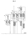
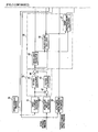
- a section in the controller C which is related to the left front wheel disc brake BA includes:
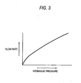
- the target fluid amount calculation module 31 and the actual fluid amount calculation module 32 calculate fluid amounts according to hydraulic pressures by following a preset map as shown in Fig. 3 .
- the actual differential pressure calculation module 33 is such as to detect a differential pressure between before and after each of the regulator valve 7, the inlet valve 9 and the outlet valve 14 of the hydraulic pressure control unit 5, and when the hydraulic pressure in the hydraulic pressure path 6 is adjusted by the regulator valve 7 while keeping the inlet valve 9 and the outlet valve 14 opened and closed, respectively, the output hydraulic pressure of the master cylinder M which is detected by the master cylinder output hydraulic pressure detector 22 and the higher hydraulic pressure of the brake hydraulic pressures of the left front wheel disc brake BA and the right rear wheel disc brake BB which are detected by the brake hydraulic pressure detectors 23, 24 are inputted into the actual differential pressure calculation module 33, and the actual differential pressure calculation module 33 calculates an actual differential pressure between before and after the regulator valve 7.
- the actual differential pressure calculation module 33 calculates an actual differential pressure between before and after each of the inlet valve 9 and the outlet valve 14.
- the hydraulic pressure control unit target controlled variable setting unit 35 includes:
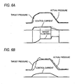
- control current for the regulator valve 7, the inlet valve 9 or the outlet valve 14 is determined based on the difference between the hydraulic pressure detected in the brake hydraulic pressure detector 23 and the target pressure which is set in target wheel brake pressure setting module 30 and the target flow rate obtained in the target flow rate calculation unit 34, and the regulator valve 7, the inlet valve 9 or the outlet valve 14 is controlled in a linear manner by the control current so determined.
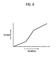
- the high select value TM_MDCAL is inputted into the target current F/B term calculation module 50 of the control current calculation unit 38 from the high select module 59 of the timer unit 40, and in the target current F/B term calculation module 50, as shown in Fig. 9 , the F/B gain changes in such a manner as to increase as the high select value TM_MDCAL increases. Namely, when hunting is liable to be generated, the controlled variable of the regulator valve 7, the inlet valves 9, 10 or the outlet valves 14, 15 is increased by increasing the F/B gain, whereby the hydraulic pressure control is enabled without promoting vibrations. Moreover, since the F/B gain is not such as to be switched depending upon the existence of hunting but such as to change continuously with change in the high select value TM_MDCAL, a smooth hydraulic pressure control can be realized, and robustness is enhanced.
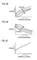
- the target rotational speed calculation module 37 is such as to operate a target rotational speed for the electric motor 17 based on the target discharge mount of the pump 18 and the rotational speed of the electric motor 17 is controlled by operating the drive duty of the electric motor 17 by the drive duty calculation unit 39 based on the target rotational speed so operated, the response can be increased while maintaining quietness by reducing the operation noise, as shown in Fig. 10A .
- optimizing the discharge amount of the pump 18 can contribute to increasing the hydraulic pressure control accuracy.
- the switch 61 is closed to make the connection in the circuit, whereas the switch 62 is opened to break the connection, and when the electric motor 17 is braked, as shown in Fig. 13B , the switch 61 is opened to break the connection in the circuit, whereas the switch 62 is closed to make the connection, so that a motor brake state is obtained.
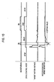
- step S1 whether or not the drive control mode of the electric motor 17 is an end mode is determined.
- drive modes for the electric motor 17 there are set modes of "stop,” “drive,” and “end.”
- the "end” mode denotes a state in which although there is no drive requirement, the electric motor 17 is rotating by virtue of inertia.
- step S3 the flow proceeds from step S3 to step S6, where a brake-on state is produced, and if it is determined at step S4 that although the drive control mode is the drive mode, the target motor voltage is exceeding a certain value, and if it is determined at step S5 that although the drive control mode is the drive mode with the target motor voltage being the certain value or less, the motor rotational speed deviation is exceeding the certain value, a brake-off state is produced at step S6.
- the control currents can be obtained in association with changes in the characteristics of the regulator valve 7, the inlet valves 9, 10 and the outlet valves 14, 15 with flow rate, thereby making it possible to enhance the control performance.
- the controller C is made to include the target discharge amount calculation module 47 for obtaining a target discharge amount for the pump 18 based on the target flow rates obtained in the target flow rate calculation unit 34 and the target rotational speed calculation module 37 for obtaining a target rotational speed for the electric motor 17 which drives the pump 18 based on the target discharge amounts obtained in the target discharge amount calculation module 47 and controls the electric motor 17 based on the target rotational speed obtained in the target rotational speed calculation module 37, the response and quietness during the hydraulic pressure control can be enhanced and a further increase in hydraulic pressure control accuracy can be realized.
- controller C since the controller C includes the pressure build-up timer 57 adapted to implement counting up normally except when the count value is cleared to "0" when the hydraulic pressure control unit 5 is controlled to shift from the pressure build-up mode to the pressure reducing mode or to the pressure holding mode and the pressure reducing timer 58 adapted to implement counting up normally except when the count value is cleared to "0" when the hydraulic pressure control unit 5 is controlled to shift from the pressure reducing mode to the pressure build-up mode or to the pressure holding mode, and since the controlled variable of the regulator valve 7, the inlet valves 9, 10 or the outlet valves 14, 15 in the hydraulic control unit 5 are made to increase as the high select value TM_MDCAL which results by high selecting the count values of the pressure build-up timer 57 and the pressure reducing timer 58 by the high select module 59 increases, the generation of control hunting can be prevented.
- the controller C since the controller C includes the pressure build-up timer 57 adapted to implement counting up normally except when the count value is cleared to "0" when the hydraulic pressure control unit
- the series circuit made up of the battery 60 and the switch 61 is connected to both the terminals of the electric motor 17 and the switch 62 for short-circuitting between both the terminals of the electric motor 17 is connected thereto in parallel to the series circuit, and since the controller C causes the switch 62 to be closed to make the connection in the circuit so as to short-circuit between both the terminals of the electric motor 17 when the target motor voltage is the certain value of less even in such a state that the electric motor 17 is being driven and the actual rotational speed of the electric motor 17 exceeds the target rotational speed beyond the predetermined value, the deceleration response of the electric motor 17 can be increased with the simple drive circuit.
- a controller includes a target fluid amount calculation module 31 which obtains target fluid amounts for wheel brakes based on target hydraulic pressures which are set in a target wheel brake pressure setting module 30, an actual fluid amount calculation module 32 which obtains actual fluid amounts for the wheel brakes based on hydraulic pressures brake hydraulic pressure detectors, and a target flow rate calculation unit 34 which obtains target flow rates for the wheel brakes based on the actual fluid amounts obtained in the actual fluid amount calculation module 32 and controls the operation of a hydraulic
Landscapes
- Physics & Mathematics (AREA)
- Engineering & Computer Science (AREA)
- Fluid Mechanics (AREA)
- Transportation (AREA)
- Mechanical Engineering (AREA)
- Electromagnetism (AREA)
- Regulating Braking Force (AREA)
Claims (5)
- Fahrzeugbremshydraulikdrucksteuer/regelsystem, umfassend:eine Hydraulikdruckversorgungsquelle (M, 18), welche Hydraulikdruck ausgibt;eine Hydraulikdruck-Steuer/Regeleinheit (5), welche zwischen der Hydraulikdruckversorgungsquelle (M, 18) und Radbremsen (BA, BB) angeordnet ist und welche Hydraulikdrücke an den Radbremsen (BA, BB) einstellt;eine Bremshydraulikdruckerfassungseinheit, welche Hydraulikdrücke an den Radbremsen (BA, BB) erfasst; undeine Steuer/Regeleinrichtung (C), welche eine Soll-Radbremsdruckeinstelleinheit (30) umfasst, welche Soll-Hydraulikdrücke für die Radbremsen (BA, BB) einstellt und welche einen Betrieb der Hydraulikdruck-Steuer/Regeleinheit (5) derart steuert/regelt, dass die Hydraulikdrücke an den Radbremsen (BA, BB) von der Soll-Radbremsdruckeinstelleinheit (30) eingestellte Soll-Hydraulikdrücke werden,dadurch gekennzeichnet, dass die Steuer/Regeleinrichtung (C) ferner umfasst:eine Soll-Fluidmengenberechnungseinheit (31), welche Soll-Fluidmengen für die Radbremsen (BA, BB) basierend auf den von der Soll-Radbremsdruckeinstelleinheit (30) eingestellten Soll-Hydraulikdrücken erhält;eine Ist-Fluidmengenberechnungseinheit (32), welche Ist-Fluidmengen für die Radbremsen (BA, BB) basierend auf den von der Bremshydraulikdruckerfassungseinheit (23, 24) erfassten Hydraulikdrücken erhält, undeine Soll-Strömungsratenberechnungseinheit (34), welche Soll-Strömungsraten für die Radbremsen (BA, BB) basierend auf den von der Soll-Fluidmengenberechnungseinheit (31) erhaltenen Soll-Fluidmengen und den von der Ist-Fluidmengenberechnungseinheit (32) erhaltenen Ist-Fluidmengen erhält, unddie Steuer/Regeleinrichtung den Betrieb der Hydraulikdruck-Steuer/Regeleinheit (5) basierend auf den von der Soll-Strömungsratenberechnungseinheit (34) erhaltenen Soll-Strömungsraten steuert/regelt.
- Fahrzeugbremshydraulikdrucksteuer/regelsystem nach Anspruch 1, wobei die Hydraulikdruck-Steuer/Regeleinheit (5) dazu ausgebildet ist, derart gesteuert/geregelt zu werden, dass sie umschaltet zu:einem Druckaufbaumodus, um zu bewirken, dass der Hydraulikdruck von der Hydraulikdruckversorgungsquelle (M, 18) an die Radbremsen (BA, BB) angelegt wird;einem Druckreduzierungsmodus, um die Hydraulikdrücke an den Radbremsen (BA, BB) abzulassen; undeinem Druckhaltemodus, um die Hydraulikdrücke an den Radbremsen (BA, BB) zu halten, unddie Steuer/Regeleinrichtung (C) den Betrieb der Hydraulikdruck-Steuer/Regeleinheit (5) steuert/regelt, indem der Betriebsmodus derselben zwischen dem Druckaufbaumodus, dem Druckreduzierungsmodus und dem Druckhaltemodus umgeschaltet wird basierend auf Vorzeichen und Absolutwerten von den von der Soll-Strömungsratenberechnungseinheit (34) erhaltenen Soll-Strömungsraten.
- Fahrzeugbremshydraulikdrucksteuer/regelsystem nach Anspruch 1, wobei die Hydraulikdruck-Steuer/Regeleinheit (5) lineare Solenoidventile (7, 9, 10, 14, 15) umfasst, welche stromgesteuert/geregelt sind, und
die Steuer/Regeleinheit (C) den an die linearen Solenoidventile (7, 9, 10, 14, 15) angelegten Strom basierend auf einer Differenz zwischen den von der Bremshydraulikdruckerfassungseinheit (23, 24) erfassten Hydraulikdrücken und den von der Soll-Bremsdruckeinstelleinheit (30) eingestellten Soll-Hydraulikdrücken und der von der Soll-Strömungsratenberechnungseinheit (34) erhaltenen Soll-Strömungsrate steuert/regelt. - Fahrzeugbremshydraulikdrucksteuer/regelsystem nach Anspruch 1, wobei die Hydraulikdruckversorgungsquelle (18) eine Pumpe ist, welche durch einen Elektromotor (17) angetrieben wird, und
die Steuer/Regeleinrichtung (C) umfasst:eine Soll-Abgabemengenberechnungseinheit (47), welche eine Soll-Abgabemenge für die Pumpe (18) basierend auf den von der Soll-Strömungsratenberechnungseinheit (34) erhaltenen Soll-Strömungsraten erhält; undeine Soll-Drehzahlberechnungseinheit (37), welche eine Soll-Drehzahl für den Elektromotor (17) basierend auf der von der Soll-Abgabemengenberechnungseinheit (47) erhaltenen Soll-Abgabemenge erhält, unddie Steuer/Regeleinrichtung (C) den Elektromotor (17) basierend auf der von der Soll-Drehzahlberechnungseinheit (37) erhaltenen Soll-Drehzahl steuert/regelt. - Fahrzeugbremshydraulikdrucksteuer/regelsystem nach Anspruch 2, wobei die Steuer/Regeleinrichtung (C) umfasst:einen Druckaufbauzeitgeber (57), welcher normalerweise ein Hochzählen ausführt, ausgenommen dann, wenn ein Zählerwert auf "0" zurückgesetzt wird, wenn die Hydraulikdruck-Steuer/Regeleinheit (5) derart gesteuert/geregelt wird, dass sie von dem Druckaufbaumodus zu dem Druckreduzierungsmodus oder dem Druckhaltemodus umschaltet; undeinen Druckreduzierungszeitgeber (58), welcher normalerweise ein Hochzählen ausführt, ausgenommen dann, wenn ein Zählerwert auf "0" zurückgesetzt wird, wenn die Hydraulikdruck-Steuer/Regeleinheit (5) so gesteuert/geregelt wird, dass sie von dem Druckreduzierungsmodus zu dem Druckaufbaumodus oder dem Druckhaltemodus umschaltet, unddie Steuer/Regeleinrichtung (C) eine Steuer/Regelvariable von der Hydraulikdruck-Steuer/Regeleinheit (5) erhöht, wenn ein hoher Auswahlwert von den Zählerwerten von dem Druckaufbauzeitgeber (57) und dem Druckreduzierungszeitgeber (58) zunimmt.
Applications Claiming Priority (1)
| Application Number | Priority Date | Filing Date | Title |
|---|---|---|---|
| JP2007144026A JP4974766B2 (ja) | 2007-05-30 | 2007-05-30 | 車両用ブレーキ液圧制御装置 |
Publications (2)
| Publication Number | Publication Date |
|---|---|
| EP1997701A1 EP1997701A1 (de) | 2008-12-03 |
| EP1997701B1 true EP1997701B1 (de) | 2009-12-23 |
Family
ID=39802440
Family Applications (1)
| Application Number | Title | Priority Date | Filing Date |
|---|---|---|---|
| EP08009954A Ceased EP1997701B1 (de) | 2007-05-30 | 2008-05-30 | Hydraulisches Drucksteuerungssystem für Fahrzeugbremsen |
Country Status (4)
| Country | Link |
|---|---|
| US (1) | US8108116B2 (de) |
| EP (1) | EP1997701B1 (de) |
| JP (1) | JP4974766B2 (de) |
| DE (1) | DE602008000432D1 (de) |
Families Citing this family (48)
| Publication number | Priority date | Publication date | Assignee | Title |
|---|---|---|---|---|
| JP4949934B2 (ja) * | 2007-06-04 | 2012-06-13 | 本田技研工業株式会社 | 車両用ブレーキ液圧制御装置 |
| JP5308394B2 (ja) * | 2008-03-31 | 2013-10-09 | 株式会社アドヴィックス | 制動制御装置 |
| JP5321885B2 (ja) * | 2008-03-31 | 2013-10-23 | 株式会社アドヴィックス | 制動制御装置 |
| JP5125813B2 (ja) * | 2008-07-02 | 2013-01-23 | 日産自動車株式会社 | 電子制御液圧ブレーキ装置 |
| US9555832B2 (en) | 2011-04-19 | 2017-01-31 | Ford Global Technologies, Llc | Display system utilizing vehicle and trailer dynamics |
| US9493187B2 (en) | 2011-04-19 | 2016-11-15 | Ford Global Technologies, Llc | Control for trailer backup assist system |
| US9969428B2 (en) | 2011-04-19 | 2018-05-15 | Ford Global Technologies, Llc | Trailer backup assist system with waypoint selection |
| US9499200B2 (en) | 2011-04-19 | 2016-11-22 | Ford Global Technologies, Llc | Trailer backup assist system with object detection |
| US9434414B2 (en) | 2011-04-19 | 2016-09-06 | Ford Global Technologies, Llc | System and method for determining a hitch angle offset |
| US9290202B2 (en) | 2011-04-19 | 2016-03-22 | Ford Global Technologies, Llc | System and method of calibrating a trailer backup assist system |
| US9238483B2 (en) | 2011-04-19 | 2016-01-19 | Ford Global Technologies, Llc | Trailer backup assist system with trajectory planner for multiple waypoints |
| US9783230B2 (en) | 2011-04-19 | 2017-10-10 | Ford Global Technologies, Llc | Trailer backup assist system with off-shoot correction |
| US9708000B2 (en) | 2011-04-19 | 2017-07-18 | Ford Global Technologies, Llc | Trajectory planner for a trailer backup assist system |
| US9937953B2 (en) | 2011-04-19 | 2018-04-10 | Ford Global Technologies, Llc | Trailer backup offset determination |
| US8909426B2 (en) | 2011-04-19 | 2014-12-09 | Ford Global Technologies | Trailer path curvature control for trailer backup assist |
| JP5624936B2 (ja) * | 2011-05-10 | 2014-11-12 | 日信工業株式会社 | 車両用ブレーキ液圧制御装置 |
| DE102011078890A1 (de) * | 2011-07-08 | 2013-01-10 | Robert Bosch Gmbh | Überwachungsvorrichtung für zumindest eine Untereinheit eines hydraulischen Bremssystems und Verfahren zum Untersuchen einer Funktionsfähigkeit zumindest einer Untereinheit eines hydraulischen Bremssystems |
| DE102013203172A1 (de) * | 2012-03-06 | 2013-09-12 | Continental Teves Ag & Co. Ohg | Verfahren zum Betreiben einer hydraulischen Anlage und Bremsanlage |
| DE102013203594A1 (de) | 2012-03-06 | 2013-09-12 | Continental Teves Ag & Co. Ohg | Verfahren zum Betreiben einer Bremsanlage für Kraftfahrzeuge sowie Bremsanlage |
| DE102013203189A1 (de) | 2012-03-06 | 2013-09-12 | Continental Teves Ag & Co. Ohg | Verfahren zur Bestimmung einer Druck-Volumen-Kennlinie einer Radbremse |
| JP5563004B2 (ja) * | 2012-03-28 | 2014-07-30 | 日信工業株式会社 | 車両用ブレーキ液圧制御装置 |
| JP5827198B2 (ja) * | 2012-10-09 | 2015-12-02 | 日信工業株式会社 | 車両用ブレーキ液圧制御装置 |
| JP5702769B2 (ja) * | 2012-12-27 | 2015-04-15 | 日信工業株式会社 | 車両用ブレーキ液圧制御システム |
| US9623904B2 (en) | 2014-06-03 | 2017-04-18 | Ford Global Technologies, Llc | Trailer curvature control with adaptive trailer length estimation |
| US9540043B2 (en) | 2014-07-30 | 2017-01-10 | Ford Global Technologies, Llc | Trailer backup assist system with active trailer braking for curvature control |
| US9522699B2 (en) | 2015-02-05 | 2016-12-20 | Ford Global Technologies, Llc | Trailer backup assist system with adaptive steering angle limits |
| US10286950B2 (en) | 2015-02-10 | 2019-05-14 | Ford Global Technologies, Llc | Speed optimized trajectory control for motor vehicles |
| US9616923B2 (en) | 2015-03-03 | 2017-04-11 | Ford Global Technologies, Llc | Topographical integration for trailer backup assist system |
| US9623859B2 (en) | 2015-04-03 | 2017-04-18 | Ford Global Technologies, Llc | Trailer curvature control and mode management with powertrain and brake support |
| US9840240B2 (en) | 2015-04-09 | 2017-12-12 | Ford Global Technologies, Llc | Trailer backup aid speed limiting via braking |
| US9744972B2 (en) | 2015-04-09 | 2017-08-29 | Ford Global Technologies, Llc | Trailer backup aid speed limiting via braking |
| US9676377B2 (en) | 2015-06-17 | 2017-06-13 | Ford Global Technologies, Llc | Speed limiting comfort enhancement |
| US9896126B2 (en) | 2015-07-08 | 2018-02-20 | Ford Global Technologies, Llc | Jackknife detection for vehicle reversing a trailer |
| JP6447399B2 (ja) * | 2015-07-24 | 2019-01-09 | 株式会社アドヴィックス | 車両用ブレーキ装置 |
| US9981662B2 (en) | 2015-10-15 | 2018-05-29 | Ford Global Technologies, Llc | Speed limiting comfort enhancement |
| US10773721B2 (en) | 2016-10-21 | 2020-09-15 | Ford Global Technologies, Llc | Control method using trailer yaw rate measurements for trailer backup assist |
| JP6699622B2 (ja) * | 2017-05-29 | 2020-05-27 | 株式会社アドヴィックス | 車両の制動制御装置 |
| US10604184B2 (en) | 2017-08-31 | 2020-03-31 | Ford Global Technologies, Llc | Adaptive steering control for robustness to errors in estimated or user-supplied trailer parameters |
| US10710585B2 (en) | 2017-09-01 | 2020-07-14 | Ford Global Technologies, Llc | Trailer backup assist system with predictive hitch angle functionality |
| JP6935712B2 (ja) * | 2017-09-26 | 2021-09-15 | 株式会社アドヴィックス | 車両の制動制御装置 |
| US10730553B2 (en) | 2017-09-27 | 2020-08-04 | Ford Global Technologies, Llc | Adaptive steering control for robustness to errors in estimated or user-supplied trailer parameters |
| JP7070145B2 (ja) | 2018-06-25 | 2022-05-18 | 株式会社アドヴィックス | 車両の制動制御装置 |
| JP7040316B2 (ja) | 2018-06-25 | 2022-03-23 | 株式会社アドヴィックス | 車両の制動制御装置 |
| US10814912B2 (en) | 2018-11-28 | 2020-10-27 | Ford Global Technologies, Llc | Trailer backup assist system having advanced user mode with selectable hitch angle limits |
| US11447132B2 (en) | 2020-02-20 | 2022-09-20 | Ford Global Technologies, Llc | Trailer hitching assistance system with dynamic vehicle control processing |
| CN113911086B (zh) * | 2021-10-26 | 2022-09-13 | 清华大学 | 商用车用气压线控制动系统制动气室压力控制方法及系统 |
| JP7823437B2 (ja) | 2022-03-10 | 2026-03-04 | 株式会社アドヴィックス | 車両の制動制御装置 |
| JP2025084299A (ja) * | 2023-11-22 | 2025-06-03 | 株式会社アドヴィックス | 車両の制動制御装置 |
Family Cites Families (27)
| Publication number | Priority date | Publication date | Assignee | Title |
|---|---|---|---|---|
| DE4329140C1 (de) * | 1993-08-30 | 1994-12-01 | Daimler Benz Ag | Bremsdruck-Steuereinrichtung |
| US6334654B1 (en) * | 1996-09-13 | 2002-01-01 | New York Air Brake Corporation | Integrated train electrical and pneumatic brakes |
| WO1998013244A1 (en) * | 1996-09-26 | 1998-04-02 | Toyota Jidosha Kabushiki Kaisha | Braking device |
| JP3496549B2 (ja) * | 1998-04-17 | 2004-02-16 | トヨタ自動車株式会社 | 液圧ブレーキ装置 |
| JP4482981B2 (ja) * | 1999-10-04 | 2010-06-16 | トヨタ自動車株式会社 | ブレーキ液圧制御装置 |
| JP4333000B2 (ja) * | 1999-12-10 | 2009-09-16 | トヨタ自動車株式会社 | 車両用ブレーキシステム |
| JP3851043B2 (ja) * | 1999-12-24 | 2006-11-29 | トヨタ自動車株式会社 | ブレーキ液圧制御装置 |
| JP2004051023A (ja) * | 2002-07-22 | 2004-02-19 | Toyota Motor Corp | 車両の制御装置 |
| JP2004268901A (ja) * | 2003-02-18 | 2004-09-30 | Nissan Motor Co Ltd | 制動制御装置 |
| JP3972835B2 (ja) | 2003-02-24 | 2007-09-05 | 日産自動車株式会社 | 電子制御液圧ブレーキ装置 |
| JP3955015B2 (ja) * | 2003-12-05 | 2007-08-08 | 日信工業株式会社 | 車両用ブレーキ装置 |
| SE0400603L (sv) * | 2004-03-09 | 2005-01-25 | Volvo Lastvagnar Ab | Metod och anordning för fördelning av bromselement hos ett motorfordon |
| JP2006069495A (ja) * | 2004-09-06 | 2006-03-16 | Hitachi Ltd | ブレーキ制御装置 |
| JP2006137221A (ja) | 2004-11-10 | 2006-06-01 | Honda Motor Co Ltd | 車両のブレーキ液圧制御装置 |
| JP4780948B2 (ja) | 2004-11-15 | 2011-09-28 | トヨタ自動車株式会社 | ブレーキ液圧制御装置 |
| CA2528903C (en) | 2004-12-20 | 2008-01-15 | Honda Motor Co., Ltd. | Braking device for motorcycle |
| US7472011B2 (en) * | 2005-01-12 | 2008-12-30 | Wabtec Holding Corporation | Brake interface module |
| JP2006224743A (ja) * | 2005-02-16 | 2006-08-31 | Advics:Kk | 制動力保持制御装置 |
| US20070087898A1 (en) * | 2005-10-18 | 2007-04-19 | Siemens Vdo Automotive Corporation | Passive Start with invalid brake ON-OFF switch state |
| JP4569475B2 (ja) * | 2006-01-11 | 2010-10-27 | トヨタ自動車株式会社 | ブレーキ制御装置 |
| JP4186991B2 (ja) * | 2006-01-31 | 2008-11-26 | トヨタ自動車株式会社 | 車両用制動装置 |
| JP4696950B2 (ja) * | 2006-02-15 | 2011-06-08 | 株式会社アドヴィックス | 車両用ブレーキ制御装置 |
| JP4835203B2 (ja) * | 2006-03-01 | 2011-12-14 | 株式会社アドヴィックス | 車両用ブレーキ制御装置 |
| JP4618169B2 (ja) * | 2006-03-13 | 2011-01-26 | 株式会社アドヴィックス | 車両用ブレーキ制御装置 |
| JP4222382B2 (ja) * | 2006-04-28 | 2009-02-12 | トヨタ自動車株式会社 | 車両制動装置 |
| JP2008260417A (ja) * | 2007-04-12 | 2008-10-30 | Hitachi Ltd | ブレーキ倍力制御装置 |
| JP4955450B2 (ja) * | 2007-05-14 | 2012-06-20 | 日立オートモティブシステムズ株式会社 | ブレーキ制御装置 |
-
2007
- 2007-05-30 JP JP2007144026A patent/JP4974766B2/ja not_active Expired - Fee Related
-
2008
- 2008-05-29 US US12/129,111 patent/US8108116B2/en not_active Expired - Fee Related
- 2008-05-30 DE DE602008000432T patent/DE602008000432D1/de active Active
- 2008-05-30 EP EP08009954A patent/EP1997701B1/de not_active Ceased
Also Published As
| Publication number | Publication date |
|---|---|
| DE602008000432D1 (de) | 2010-02-04 |
| JP2008296704A (ja) | 2008-12-11 |
| EP1997701A1 (de) | 2008-12-03 |
| US8108116B2 (en) | 2012-01-31 |
| US20080300763A1 (en) | 2008-12-04 |
| JP4974766B2 (ja) | 2012-07-11 |
Similar Documents
| Publication | Publication Date | Title |
|---|---|---|
| EP1997701B1 (de) | Hydraulisches Drucksteuerungssystem für Fahrzeugbremsen | |
| EP2000375B1 (de) | Hydraulisches Drucksteuerungssystem für Fahrzeugbremsen | |
| US8794716B2 (en) | Brake fluid pressure control apparatus for vehicle | |
| US7926887B2 (en) | Brake control system and brake control method | |
| JP3287259B2 (ja) | 制動力制御装置 | |
| EP0425261B1 (de) | Fahrzeug-Bremsflüssigkeitsdruck-Steuerverfahren | |
| JP2006312384A (ja) | 車両の回生制動および摩擦制動装置 | |
| JP3617180B2 (ja) | 制動力制御装置 | |
| US8155855B2 (en) | Vehicle motion control apparatus | |
| JP4555746B2 (ja) | 車両用ブレーキ液圧制御装置 | |
| JP4987575B2 (ja) | 車両用ブレーキ液圧制御装置 | |
| JP4717503B2 (ja) | 車両用ブレーキ装置 | |
| JP4241505B2 (ja) | 車輌の制動制御装置 | |
| JP2006312386A (ja) | 車両の回生制動および摩擦制動装置 | |
| JP4953925B2 (ja) | 車両のアンチロックブレーキ制御装置 | |
| JP4590301B2 (ja) | 車両用ブレーキ制御装置 | |
| JP2008302717A (ja) | 車両のアンチロックブレーキ制御装置 | |
| US8140233B2 (en) | Braking control device | |
| JP4999554B2 (ja) | 車両用ブレーキ液圧制御装置 | |
| JP2009023463A (ja) | 車両用ブレーキ液圧制御装置 | |
| JPH08268256A (ja) | ブレーキ制御装置 | |
| JP4832362B2 (ja) | 車両用ブレーキ液圧制御装置 | |
| JP2001219833A (ja) | 車両用ブレーキ液圧制御装置 | |
| KR100482957B1 (ko) | 안티록 브레이크 시스템의 노면변화 감지 및 제어방법 | |
| KR19980054788A (ko) | 안티록 브레이크 시스템의 제어방법 |
Legal Events
| Date | Code | Title | Description |
|---|---|---|---|
| PUAI | Public reference made under article 153(3) epc to a published international application that has entered the european phase |
Free format text: ORIGINAL CODE: 0009012 |
|
| 17P | Request for examination filed |
Effective date: 20080530 |
|
| AK | Designated contracting states |
Kind code of ref document: A1 Designated state(s): AT BE BG CH CY CZ DE DK EE ES FI FR GB GR HR HU IE IS IT LI LT LU LV MC MT NL NO PL PT RO SE SI SK TR |
|
| AX | Request for extension of the european patent |
Extension state: AL BA MK RS |
|
| 17Q | First examination report despatched |
Effective date: 20081106 |
|
| GRAP | Despatch of communication of intention to grant a patent |
Free format text: ORIGINAL CODE: EPIDOSNIGR1 |
|
| AKX | Designation fees paid |
Designated state(s): DE GB |
|
| GRAS | Grant fee paid |
Free format text: ORIGINAL CODE: EPIDOSNIGR3 |
|
| GRAA | (expected) grant |
Free format text: ORIGINAL CODE: 0009210 |
|
| RIN1 | Information on inventor provided before grant (corrected) |
Inventor name: TAKAHASHI, SUSUMUC/O HONDA R&D CO., LTD. Inventor name: NAKADA, ATSUSHIC/O HONDA R&D CO. LTD. Inventor name: MORI, RYOJIC/O HONDA R&D CO., LTD. Inventor name: KOMORI, TEPPEIC/O HONDA R&D CO., LTD. |
|
| AK | Designated contracting states |
Kind code of ref document: B1 Designated state(s): DE GB |
|
| REG | Reference to a national code |
Ref country code: GB Ref legal event code: FG4D |
|
| REF | Corresponds to: |
Ref document number: 602008000432 Country of ref document: DE Date of ref document: 20100204 Kind code of ref document: P |
|
| PLBE | No opposition filed within time limit |
Free format text: ORIGINAL CODE: 0009261 |
|
| STAA | Information on the status of an ep patent application or granted ep patent |
Free format text: STATUS: NO OPPOSITION FILED WITHIN TIME LIMIT |
|
| 26N | No opposition filed |
Effective date: 20100924 |
|
| PGFP | Annual fee paid to national office [announced via postgrant information from national office to epo] |
Ref country code: GB Payment date: 20130529 Year of fee payment: 6 |
|
| GBPC | Gb: european patent ceased through non-payment of renewal fee |
Effective date: 20140530 |
|
| PG25 | Lapsed in a contracting state [announced via postgrant information from national office to epo] |
Ref country code: GB Free format text: LAPSE BECAUSE OF NON-PAYMENT OF DUE FEES Effective date: 20140530 |
|
| PGFP | Annual fee paid to national office [announced via postgrant information from national office to epo] |
Ref country code: DE Payment date: 20150527 Year of fee payment: 8 |
|
| REG | Reference to a national code |
Ref country code: DE Ref legal event code: R119 Ref document number: 602008000432 Country of ref document: DE |
|
| PG25 | Lapsed in a contracting state [announced via postgrant information from national office to epo] |
Ref country code: DE Free format text: LAPSE BECAUSE OF NON-PAYMENT OF DUE FEES Effective date: 20161201 |