EP1997732B1 - Verbesserungen bei oder im Zusammenhang mit Notbeleuchtung - Google Patents
Verbesserungen bei oder im Zusammenhang mit Notbeleuchtung Download PDFInfo
- Publication number
- EP1997732B1 EP1997732B1 EP08251425.8A EP08251425A EP1997732B1 EP 1997732 B1 EP1997732 B1 EP 1997732B1 EP 08251425 A EP08251425 A EP 08251425A EP 1997732 B1 EP1997732 B1 EP 1997732B1
- Authority
- EP
- European Patent Office
- Prior art keywords
- insert
- holder
- channel
- photoluminescent
- base wall
- Prior art date
- Legal status (The legal status is an assumption and is not a legal conclusion. Google has not performed a legal analysis and makes no representation as to the accuracy of the status listed.)
- Ceased
Links
Images




Classifications
-
- B—PERFORMING OPERATIONS; TRANSPORTING
- B64—AIRCRAFT; AVIATION; COSMONAUTICS
- B64D—EQUIPMENT FOR FITTING IN OR TO AIRCRAFT; FLIGHT SUITS; PARACHUTES; ARRANGEMENT OR MOUNTING OF POWER PLANTS OR PROPULSION TRANSMISSIONS IN AIRCRAFT
- B64D25/00—Emergency apparatus or devices, not otherwise provided for
-
- A—HUMAN NECESSITIES
- A62—LIFE-SAVING; FIRE-FIGHTING
- A62B—DEVICES, APPARATUS OR METHODS FOR LIFE-SAVING
- A62B3/00—Devices or single parts for facilitating escape from buildings or the like, e.g. protection shields, protection screens; Portable devices for preventing smoke penetrating into distinct parts of buildings
-
- B—PERFORMING OPERATIONS; TRANSPORTING
- B60—VEHICLES IN GENERAL
- B60Q—ARRANGEMENT OF SIGNALLING OR LIGHTING DEVICES, THE MOUNTING OR SUPPORTING THEREOF OR CIRCUITS THEREFOR, FOR VEHICLES IN GENERAL
- B60Q3/00—Arrangement of lighting devices for vehicle interiors; Lighting devices specially adapted for vehicle interiors
- B60Q3/40—Arrangement of lighting devices for vehicle interiors; Lighting devices specially adapted for vehicle interiors specially adapted for specific vehicle types
- B60Q3/41—Arrangement of lighting devices for vehicle interiors; Lighting devices specially adapted for vehicle interiors specially adapted for specific vehicle types for mass transit vehicles, e.g. buses
- B60Q3/46—Emergency lighting, e.g. for escape routes
-
- B—PERFORMING OPERATIONS; TRANSPORTING
- B60—VEHICLES IN GENERAL
- B60Q—ARRANGEMENT OF SIGNALLING OR LIGHTING DEVICES, THE MOUNTING OR SUPPORTING THEREOF OR CIRCUITS THEREFOR, FOR VEHICLES IN GENERAL
- B60Q3/00—Arrangement of lighting devices for vehicle interiors; Lighting devices specially adapted for vehicle interiors
- B60Q3/70—Arrangement of lighting devices for vehicle interiors; Lighting devices specially adapted for vehicle interiors characterised by the purpose
- B60Q3/78—Arrangement of lighting devices for vehicle interiors; Lighting devices specially adapted for vehicle interiors characterised by the purpose for generating luminous strips, e.g. for marking trim component edges
-
- B—PERFORMING OPERATIONS; TRANSPORTING
- B64—AIRCRAFT; AVIATION; COSMONAUTICS
- B64D—EQUIPMENT FOR FITTING IN OR TO AIRCRAFT; FLIGHT SUITS; PARACHUTES; ARRANGEMENT OR MOUNTING OF POWER PLANTS OR PROPULSION TRANSMISSIONS IN AIRCRAFT
- B64D47/00—Equipment not otherwise provided for
- B64D47/02—Arrangements or adaptations of signal or lighting devices
-
- F—MECHANICAL ENGINEERING; LIGHTING; HEATING; WEAPONS; BLASTING
- F21—LIGHTING
- F21K—NON-ELECTRIC LIGHT SOURCES USING LUMINESCENCE; LIGHT SOURCES USING ELECTROCHEMILUMINESCENCE; LIGHT SOURCES USING CHARGES OF COMBUSTIBLE MATERIAL; LIGHT SOURCES USING SEMICONDUCTOR DEVICES AS LIGHT-GENERATING ELEMENTS; LIGHT SOURCES NOT OTHERWISE PROVIDED FOR
- F21K2/00—Non-electric light sources using luminescence; Light sources using electrochemiluminescence
-
- G—PHYSICS
- G08—SIGNALLING
- G08B—SIGNALLING SYSTEMS, e.g. PERSONAL CALLING SYSTEMS; ORDER TELEGRAPHS; ALARM SYSTEMS
- G08B7/00—Signalling systems according to two or more of groups G08B3/00 - G08B6/00
- G08B7/06—Signalling systems according to two or more of groups G08B3/00 - G08B6/00 using electric transmission, e.g. involving audible and visible signalling through the use of sound and light sources
- G08B7/066—Signalling systems according to two or more of groups G08B3/00 - G08B6/00 using electric transmission, e.g. involving audible and visible signalling through the use of sound and light sources guiding along a path, e.g. evacuation path lighting strip
-
- G—PHYSICS
- G09—EDUCATION; CRYPTOGRAPHY; DISPLAY; ADVERTISING; SEALS
- G09F—DISPLAYING; ADVERTISING; SIGNS; LABELS OR NAME-PLATES; SEALS
- G09F13/00—Illuminated signs; Luminous advertising
- G09F13/20—Illuminated signs; Luminous advertising with luminescent surfaces or parts
-
- G—PHYSICS
- G09—EDUCATION; CRYPTOGRAPHY; DISPLAY; ADVERTISING; SEALS
- G09F—DISPLAYING; ADVERTISING; SIGNS; LABELS OR NAME-PLATES; SEALS
- G09F19/00—Advertising or display means not otherwise provided for
- G09F19/22—Advertising or display means on roads, walls or similar surfaces, e.g. illuminated
- G09F19/228—Ground signs, i.e. display signs fixed on the ground
-
- B—PERFORMING OPERATIONS; TRANSPORTING
- B64—AIRCRAFT; AVIATION; COSMONAUTICS
- B64D—EQUIPMENT FOR FITTING IN OR TO AIRCRAFT; FLIGHT SUITS; PARACHUTES; ARRANGEMENT OR MOUNTING OF POWER PLANTS OR PROPULSION TRANSMISSIONS IN AIRCRAFT
- B64D11/00—Passenger or crew accommodation; Flight-deck installations not otherwise provided for
- B64D2011/0038—Illumination systems for cabins as a whole
-
- F—MECHANICAL ENGINEERING; LIGHTING; HEATING; WEAPONS; BLASTING
- F21—LIGHTING
- F21W—INDEXING SCHEME ASSOCIATED WITH SUBCLASSES F21K, F21L, F21S and F21V, RELATING TO USES OR APPLICATIONS OF LIGHTING DEVICES OR SYSTEMS
- F21W2107/00—Use or application of lighting devices on or in particular types of vehicles
- F21W2107/30—Use or application of lighting devices on or in particular types of vehicles for aircraft
Definitions
- the holder grips the marginal edge of a floor covering received in the groove when the insert is fitted in the channel. In this way, the edge of the floor covering is positively held in place without the need for separate grippers.
- the holder 33 is an extrusion of one or more plastics such as a blend of polycarbonate and acrylonitrile butadiene styrene (ABS) although it will be understood that other materials may be employed.
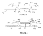
- the holder 33 has a base wall 39 and a pair of longitudinally extending sidewalls 41,43 upstanding from the base wall 39 and inset from the lateral edges to define therewith the channel 37.
- the sidewalls 41,43 terminate at the upper end in inwardly directed lips 45,47 and outwardly directed flanges 49,51 contiguous with the lips 45,47.
- the insert 35 and channel 37 are of substantially matching rectangular cross-section and the insert 35 is releasably secured in the channel 37 by the lips 45,47 that locate over the upper side edges of the insert 35.
- the holder 33 and insert 35 are configured so that the track has a substantially continuous upper surface with little or no gaps in which liquids or solids can become trapped.
- the insert 35 and channel 37 may have matching cross-sections other than rectangular and be configured to secure releasably the insert 35 in the channel 37 by any suitable means, for example a snap fit, interference fit, friction fit, mechanical interlock. In some case it may not be necessary for the insert 35 and channel 37 to have matching cross-sections although it is preferred that the insert 35 and channel 37 are configured so that the track presents a substantially continuous upper surface, i.e. with no gaps to trap dirt or liquid.
- the track 31 preferably comprises a plurality of sections of pre-formed length, for example 1 or 2 metre lengths, laid end to end or at right angles to each other on the floor of the cabin 13.
- a section can also be cut into a shorter length to enable the track 31 to be adapted to suit the layout of the seats and exits in a particular aircraft.
- Each section has the insert 35 extending from one end to the other end so that, when sections are laid end to end or at right angles, the light emitted by the photoluminescent members 61 is substantially unbroken along the length of the track 31 and provides a continuous cue from any point of the main aisle 12 and exit aisles 15,16,17,18 to an exit.
- Figure 4 shows an arrangement in which the side edges of the casing 57 are rebated to receive the lips 45,47 so that the insert 35 is positively retained in the channel 37 with a substantially flush fit and the upper surface of the track is preferably smooth with no steps or large gaps in which dirt or liquid may be trapped.
- the side edges are rebated on both upper and lower faces of the casing so that the insert 35 can be fitted either way up and is preferably symmetrical about a centre plane between the faces. It will be understood, however that rebates may be provided on one face only if the insert 35 is not intended to be reversible.
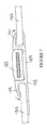
- FIG. 5 to 10 another embodiment according to the invention is shown in which like reference numerals in the series 100 are used to indicate parts corresponding to the embodiment of Figures 2 and 3 .
- the insert 135 is gripped between the sidewalls 141,143 and the lips 145,147 are urged to locate in longitudinal rebated edge portions 135a,135b of the insert 135 to retain the insert 135 in position due to the resilience of the sidewalls 141,143 as shown in Figure 7 .
- the insert 135 can be firmly located and held in position within the channel 137 eliminating any free-play or rattling without the need to use any additional means to secure the insert 135 such as adhesive tape.
- the upper face of the insert is curved to match the curvature of the flanges 149,151. This is not essential and the upper face may be flat.
- Another modification of the holder 133 is the asymmetric configuration of the base wall 139 so that, on one side of the holder 133, the base wall 139 extends laterally beyond the edge of the flange 149 and, on the other side of the holder 133, the base wall 139 is slightly narrower and inset from the edge of the flange 151.
- the flange 151 can be butted up against a wall or other surface allowing the track to be installed close to the wall without the need to fit a small strip of floor covering to conceal the base wall 139 or remove part of the base wall 139 before installation, for example, when fitting the track at the lateral sides of a stairway.
- the base wall 139 could be slightly narrower and inset from the edge of the flanges on both sides of the holder 133.
Landscapes
- Engineering & Computer Science (AREA)
- Physics & Mathematics (AREA)
- Business, Economics & Management (AREA)
- Emergency Management (AREA)
- Mechanical Engineering (AREA)
- General Physics & Mathematics (AREA)
- Aviation & Aerospace Engineering (AREA)
- Health & Medical Sciences (AREA)
- General Health & Medical Sciences (AREA)
- Theoretical Computer Science (AREA)
- General Engineering & Computer Science (AREA)
- Electromagnetism (AREA)
- Accounting & Taxation (AREA)
- Marketing (AREA)
- Non-Portable Lighting Devices Or Systems Thereof (AREA)
- Arrangement Of Elements, Cooling, Sealing, Or The Like Of Lighting Devices (AREA)
- Fastening Of Light Sources Or Lamp Holders (AREA)
Claims (13)
- Eine fotolumineszierende Schiene für ein Notbeleuchtungssystem, das eine längliche Halterung (33; 133) und einen länglichen fotolumineszierenden Einsatz (35, 135) umfasst, wobei die Halterung (33; 133) einen Kanal (37; 137) aufweist, der sich in der Längsrichtung der Halterung (33; 133) erstreckt und über Seitenwände (41, 43; 141, 143), eine Basiswand (39; 139) und einen Eingang verfügt und eine Öffnung in einer Oberfläche der Halterung (33;133) definiert, welche sich während der Anwendung zuoberst auf der Schiene (31; 131) befindet, worin der Einsatz (35; 135) zwischen den Seitenwänden (41, 43; 141, 143) lösbar befestigt und gehalten wird, sodass eine Oberfläche des Einsatzes (35; 135) innerhalb der Öffnung exponiert wird, dadurch gekennzeichnet, dass die oberste Fläche der Halterung (33; 133) durch einen Längsflansch (49, 51; 149, 151) auf mindestens einer Seite des Kanals (37; 137) definiert wird, der mit der Basiswand (39; 139) eine sich längsseitig erstreckende Nute (53, 55; 153, 155) definiert, in die eine Randkante eines Bodenbelags (152) aufgenommen werden kann, wobei die Halterung (33; 133) als Reaktion auf das Einlegen der Einsatzes (35; 135) im Kanal (37; 137) imstande ist, die Randkante des Bodenbelages, die in die Nute (53, 55; 153, 155) aufgenommen wird, festzuhalten.
- Eine fotolumineszierende Schiene gemäß Anspruch 1, wobei die Seitenwände (41; 43; 141, 143) am Eingang in Ansätzen (45, 47; 145, 147) enden, die sich nach innen ausdehnen und mit Kantenabschnitten des Einsatzes (35; 135) zusammenwirken, um den Einsatz (35; 135) im Kanal (37; 137) festzuhalten.
- Eine fotolumineszierende Schiene gemäß Anspruch 2, wobei die Ansätze (45, 47; 145, 147) in gefalzte Kantenabschnitte (135a, b) des Einsatzes (35; 135) eingreifen, sodass die oberste Fläche der Halterung (33; 133) im Wesentlichen an die oberste Fläche des Einsatzes (35; 135) angrenzt.
- Eine fotolumineszierende Schiene gemäß einem vorhergehenden Anspruch, wobei die oberste Fläche der Halterung (33; 133) durch Längsflansche (49, 51; 149, 151) auf beiden Seiten des Kanals (37; 137) definiert wird, welche wiederum sich mit der Basiswand (39, 139) in die Längsrichtung erstreckende Nuten (53, 55; 153, 155) definiert.
- Eine fotolumineszierende Schiene gemäß Anspruch 4, wobei die Basiswand (139) sich seitlich über den Flansch (149) hinaus auf einer Seite der Halterung (133) erstreckt.
- Eine fotolumineszierende Schiene gemäß einem vorhergehenden Anspruch, wobei die Seitenwände (41, 43; 141, 143) der Halterung vor dem Einführen des Einsatzes von der Basiswand (39; 139) zum Eingang des Kanals (37; 137) hin zusammenlaufen.
- Eine fotolumineszierende Schiene gemäß Anspruch 6, wobei die Seitenwände (41, 43; 141, 143) relativ zur Basiswand (39; 139) schwenkbar sind, wenn der Einsatz (35; 135) sich im Kanal (37; 137) befindet.
- Eine fotolumineszierende Schiene gemäß einem vorhergehenden Anspruch, wobei die Basiswand (139) der Halterung (133) mit Nuten (139a, b), die an die Seitenwände (141, 143) innerhalb des Kanals (137) angrenzen, versehen ist.
- Eine fotolumineszierende Schiene gemäß einem vorhergehenden Anspruch, wobei der Einsatz (35) umkehrbar ist und von beiden Seiten im Kanal (37) montiert werden kann.
- Ein Notbeleuchtungssystem, bestehend aus einer fotolumineszierenden Schiene (31; 131) gemäß einem vorhergehenden Anspruch, die angeordnet ist, um einen Fluchtweg zu identifizieren.
- Das Notbeleuchtungssystem gemäß Anspruch 10, wobei der Fluchtweg zwischen einem Paar fotolumineszierenden Schienen (1) definiert ist.
- Ein Notbeleuchtungssystem gemäß Anspruch 10 oder Anspruch 11, wobei der Fluchtweg einen Treppenaufgang beinhaltet.
- Ein PKW, der mit einem Notbeleuchtungssystem gemäß einem der Ansprüche 10 bis 12 ausgestattet ist.
Applications Claiming Priority (2)
| Application Number | Priority Date | Filing Date | Title |
|---|---|---|---|
| GB0707250A GB0707250D0 (en) | 2007-04-14 | 2007-04-14 | Improvements in or relating to emergency lighting |
| GB0712174A GB0712174D0 (en) | 2007-06-25 | 2007-06-25 | Improvements in or relating to emergency lighting |
Publications (3)
| Publication Number | Publication Date |
|---|---|
| EP1997732A2 EP1997732A2 (de) | 2008-12-03 |
| EP1997732A3 EP1997732A3 (de) | 2011-03-02 |
| EP1997732B1 true EP1997732B1 (de) | 2013-06-26 |
Family
ID=39433600
Family Applications (1)
| Application Number | Title | Priority Date | Filing Date |
|---|---|---|---|
| EP08251425.8A Ceased EP1997732B1 (de) | 2007-04-14 | 2008-04-14 | Verbesserungen bei oder im Zusammenhang mit Notbeleuchtung |
Country Status (3)
| Country | Link |
|---|---|
| US (1) | US8475024B2 (de) |
| EP (1) | EP1997732B1 (de) |
| GB (1) | GB2448424B (de) |
Families Citing this family (27)
| Publication number | Priority date | Publication date | Assignee | Title |
|---|---|---|---|---|
| US20090309763A1 (en) * | 2008-06-17 | 2009-12-17 | Hans-Christian Lierow | Emergency lighting for a helicopter |
| DE102009007491B4 (de) * | 2009-02-05 | 2013-03-28 | Airbus Operations Gmbh | Türbereich eines Luftfahrzeugs |
| US20120029765A1 (en) * | 2010-07-30 | 2012-02-02 | Sheffer Eric R | Emergency egress lighting system |
| CN103620656B (zh) * | 2011-07-01 | 2017-05-17 | 飞利浦灯具控股公司 | 用于将人引导至参考地点的方法和用在这种方法中的包括多个光源的照明系统 |
| DE102012006902A1 (de) * | 2012-04-05 | 2013-10-10 | Lufthansa Technik Ag | Fluchtwegmarkierung mit einem Leuchtstreifen aus photolumineszentem Material |
| CA2881944A1 (en) * | 2012-08-14 | 2014-02-20 | Zodiac Aerotechnics | Improved utilization for aircraft airstair space and fuel cell system integration |
| DE102012016046B3 (de) * | 2012-08-14 | 2013-12-24 | Lufthansa Technik Ag | Verfahren zum Herstellen einer Fluchtwegmarkierung für Flugzeuge sowie eine solche |
| GB201305803D0 (en) * | 2013-03-28 | 2013-05-15 | Saf T Glo Ltd | Emergency lighting |
| US9992841B2 (en) | 2013-04-19 | 2018-06-05 | Lutron Electronics Co., Inc. | Systems and methods for controlling color temperature |
| US9205932B2 (en) * | 2013-05-01 | 2015-12-08 | The Boeing Company | Method and system for determination of performance and response to electromagnetic radiation |
| GB2516614A (en) * | 2013-05-24 | 2015-02-04 | Glowroute Products Ltd | Photoluminescent devices suited for a broad range of applications |
| US20150028177A1 (en) * | 2013-07-24 | 2015-01-29 | Michael Vargas | Trailer jack stand support |
| GB2521875A (en) * | 2014-01-07 | 2015-07-08 | Saf T Glo Ltd | Signs |
| GB2524106B (en) * | 2014-03-14 | 2020-09-23 | Saf T Glo Ltd | Lighting systems |
| US10279910B2 (en) * | 2014-03-14 | 2019-05-07 | Saf-T-Glo Limited | Lighting systems |
| GB2529442B (en) * | 2014-08-20 | 2018-07-18 | Jaguar Land Rover Ltd | Illumination system |
| US9975470B2 (en) * | 2014-09-19 | 2018-05-22 | Jac Products, Inc. | Motor vehicle accessory component having modular light assembly |
| EP3217444A4 (de) * | 2014-11-04 | 2018-08-22 | NS Materials Inc. | Wellenlängenumwandlungselement, lichtemittierende vorrichtung damit, lichtemittierendes element, lichtquellenvorrichtung, anzeigevorrichtung lichtleiterelement und verfahren zur herstellung eines wellenlängenumwandlungselements |
| DE102015217406A1 (de) * | 2015-09-11 | 2017-03-16 | Lufthansa Technik Ag | Fluchtwegmarkierung für Flugzeuge |
| US10647247B2 (en) | 2017-11-07 | 2020-05-12 | Jac Products, Inc. | Vehicle article carrier apparatus for supporting articles of vehicle having a cross-bar including a heat sink arranged on a second surface for dissipating heat |
| GB201813139D0 (en) * | 2018-08-10 | 2018-09-26 | Saf T Glo Ltd | Emergency lighting |
| GB201820277D0 (en) * | 2018-12-12 | 2019-01-30 | Saf T Glo Ltd | Emergency lighting system |
| US11192496B2 (en) | 2019-12-17 | 2021-12-07 | The Boeing Company | Illuminated vehicle panel and method for manufacturing an illuminated vehicle panel |
| WO2022079345A1 (en) * | 2020-10-14 | 2022-04-21 | Glowway Oy Ltd | Strip forming a caution or warning stripe |
| FI129880B (fi) * | 2021-02-24 | 2022-10-14 | Glowway Oy Ltd | Liukueste- ja huomiolista |
| GB202117498D0 (en) * | 2021-12-03 | 2022-01-19 | Saf T Glo Ltd | Aircraft emergency way guidance assemblies |
| GB2638968A (en) * | 2024-03-01 | 2025-09-10 | Stg Aerospace Ltd | Sustainable aircraft floorpath marking |
Family Cites Families (12)
| Publication number | Priority date | Publication date | Assignee | Title |
|---|---|---|---|---|
| GB8704111D0 (en) * | 1987-02-23 | 1987-04-01 | Shinebuild Ltd | Structural element |
| GB9217672D0 (en) * | 1992-08-20 | 1992-09-30 | Gradus Ltd | Stair nosing |
| US5775016A (en) * | 1995-07-03 | 1998-07-07 | Chien; Tseng-Lu | Illuminated safety guide |
| US5499170A (en) * | 1994-10-18 | 1996-03-12 | Gagne; Bertrand | Lighting system |
| WO1996033093A1 (en) * | 1995-04-20 | 1996-10-24 | Saf-T-Glo Aerospace Limited | Emergency lighting |
| DE29608585U1 (de) * | 1995-10-04 | 1996-10-10 | P.E.R. Flucht- und Rettungsleitsysteme GmbH, 22885 Barsbüttel | Vorrichtung zur Ausbildung nachleuchtender Signalflächen |
| US5724909A (en) * | 1997-02-19 | 1998-03-10 | Burke Industries, Inc. | Passive pathway marking system |
| US6237266B1 (en) * | 1997-07-11 | 2001-05-29 | Daniel J. Tassey | Evacuation route having photoluminescent indicators |
| GB2328064A (en) * | 1997-08-09 | 1999-02-10 | Euro Passive Fire Protection L | Illuminating apparatus |
| GB2366362A (en) * | 2000-08-25 | 2002-03-06 | Stg Aerospace Ltd | Emergency lighting comprising a reversible track surrounding a photoluminescent insert |
| GB2365113B (en) * | 2000-07-25 | 2004-11-10 | Stg Aerospace Ltd | Improvements in or relating to emergency lighting |
| GB0522451D0 (en) * | 2005-11-03 | 2005-12-14 | Saf T Glo Ltd | Improvements in or relating to emergency lighting |
-
2008
- 2008-04-14 GB GB0806732.4A patent/GB2448424B/en not_active Expired - Fee Related
- 2008-04-14 US US12/102,404 patent/US8475024B2/en not_active Expired - Fee Related
- 2008-04-14 EP EP08251425.8A patent/EP1997732B1/de not_active Ceased
Also Published As
| Publication number | Publication date |
|---|---|
| EP1997732A3 (de) | 2011-03-02 |
| GB2448424A (en) | 2008-10-15 |
| US8475024B2 (en) | 2013-07-02 |
| GB0806732D0 (en) | 2008-05-14 |
| EP1997732A2 (de) | 2008-12-03 |
| US20080253139A1 (en) | 2008-10-16 |
| GB2448424B (en) | 2012-04-04 |
Similar Documents
| Publication | Publication Date | Title |
|---|---|---|
| US8475024B2 (en) | Emergency lighting | |
| US6874919B2 (en) | Emergency lighting | |
| EP2799287B1 (de) | Notbeleuchtung | |
| EP2626850B1 (de) | Schilder | |
| US5961072A (en) | Emergency lighting | |
| US5499170A (en) | Lighting system | |
| EP1249012A1 (de) | Notbeleuchtung | |
| EP0828657B1 (de) | Notbeleuchtungseinheit | |
| US7473003B2 (en) | Emergency lighting | |
| US8393572B2 (en) | Floor element with illumination | |
| US11167692B2 (en) | Emergency lighting | |
| US7367699B2 (en) | Emergency light in a multilevel aeroplane | |
| US20060201293A1 (en) | Lighting apparatus | |
| GB2366362A (en) | Emergency lighting comprising a reversible track surrounding a photoluminescent insert | |
| JP4288262B2 (ja) | 鉄道車両用乗降口の床構造 | |
| US20200223355A1 (en) | Emergency lighting system | |
| US958542A (en) | Illuminated threshold. | |
| US20260117937A1 (en) | Lightweight phosphorescent strip | |
| FI119255B (fi) | Läpinäkyvä ovi ja menetelmä läpinäkyvän oven törmäyksen estoon | |
| HK1076078B (en) | Emergency light in a multilevel aeroplane |
Legal Events
| Date | Code | Title | Description |
|---|---|---|---|
| PUAI | Public reference made under article 153(3) epc to a published international application that has entered the european phase |
Free format text: ORIGINAL CODE: 0009012 |
|
| AK | Designated contracting states |
Kind code of ref document: A2 Designated state(s): AT BE BG CH CY CZ DE DK EE ES FI FR GB GR HR HU IE IS IT LI LT LU LV MC MT NL NO PL PT RO SE SI SK TR |
|
| AX | Request for extension of the european patent |
Extension state: AL BA MK RS |
|
| PUAL | Search report despatched |
Free format text: ORIGINAL CODE: 0009013 |
|
| AK | Designated contracting states |
Kind code of ref document: A3 Designated state(s): AT BE BG CH CY CZ DE DK EE ES FI FR GB GR HR HU IE IS IT LI LT LU LV MC MT NL NO PL PT RO SE SI SK TR |
|
| AX | Request for extension of the european patent |
Extension state: AL BA MK RS |
|
| 17P | Request for examination filed |
Effective date: 20110902 |
|
| AKX | Designation fees paid |
Designated state(s): DE FR GB |
|
| 17Q | First examination report despatched |
Effective date: 20111116 |
|
| GRAP | Despatch of communication of intention to grant a patent |
Free format text: ORIGINAL CODE: EPIDOSNIGR1 |
|
| GRAS | Grant fee paid |
Free format text: ORIGINAL CODE: EPIDOSNIGR3 |
|
| GRAA | (expected) grant |
Free format text: ORIGINAL CODE: 0009210 |
|
| RBV | Designated contracting states (corrected) |
Designated state(s): DE FR |
|
| AK | Designated contracting states |
Kind code of ref document: B1 Designated state(s): DE FR |
|
| REG | Reference to a national code |
Ref country code: DE Ref legal event code: R096 Ref document number: 602008025551 Country of ref document: DE Effective date: 20130822 |
|
| PLBE | No opposition filed within time limit |
Free format text: ORIGINAL CODE: 0009261 |
|
| STAA | Information on the status of an ep patent application or granted ep patent |
Free format text: STATUS: NO OPPOSITION FILED WITHIN TIME LIMIT |
|
| 26N | No opposition filed |
Effective date: 20140327 |
|
| REG | Reference to a national code |
Ref country code: DE Ref legal event code: R097 Ref document number: 602008025551 Country of ref document: DE Effective date: 20140327 |
|
| REG | Reference to a national code |
Ref country code: FR Ref legal event code: PLFP Year of fee payment: 9 |
|
| REG | Reference to a national code |
Ref country code: FR Ref legal event code: PLFP Year of fee payment: 10 |
|
| REG | Reference to a national code |
Ref country code: FR Ref legal event code: PLFP Year of fee payment: 11 |
|
| PGFP | Annual fee paid to national office [announced via postgrant information from national office to epo] |
Ref country code: DE Payment date: 20180411 Year of fee payment: 11 |
|
| PGFP | Annual fee paid to national office [announced via postgrant information from national office to epo] |
Ref country code: FR Payment date: 20180416 Year of fee payment: 11 |
|
| REG | Reference to a national code |
Ref country code: DE Ref legal event code: R119 Ref document number: 602008025551 Country of ref document: DE |
|
| PG25 | Lapsed in a contracting state [announced via postgrant information from national office to epo] |
Ref country code: DE Free format text: LAPSE BECAUSE OF NON-PAYMENT OF DUE FEES Effective date: 20191101 |
|
| PG25 | Lapsed in a contracting state [announced via postgrant information from national office to epo] |
Ref country code: FR Free format text: LAPSE BECAUSE OF NON-PAYMENT OF DUE FEES Effective date: 20190430 |