EP1997733A2 - Système de transport de moteur de turbine à gaz - Google Patents
Système de transport de moteur de turbine à gaz Download PDFInfo
- Publication number
- EP1997733A2 EP1997733A2 EP08251884A EP08251884A EP1997733A2 EP 1997733 A2 EP1997733 A2 EP 1997733A2 EP 08251884 A EP08251884 A EP 08251884A EP 08251884 A EP08251884 A EP 08251884A EP 1997733 A2 EP1997733 A2 EP 1997733A2
- Authority
- EP
- European Patent Office
- Prior art keywords
- support member
- transport system
- turbine engine
- gas turbine
- engine
- Prior art date
- Legal status (The legal status is an assumption and is not a legal conclusion. Google has not performed a legal analysis and makes no representation as to the accuracy of the status listed.)
- Withdrawn
Links
Images







Classifications
-
- B—PERFORMING OPERATIONS; TRANSPORTING
- B64—AIRCRAFT; AVIATION; COSMONAUTICS
- B64F—GROUND OR AIRCRAFT-CARRIER-DECK INSTALLATIONS SPECIALLY ADAPTED FOR USE IN CONNECTION WITH AIRCRAFT; DESIGNING, MANUFACTURING, ASSEMBLING, CLEANING, MAINTAINING OR REPAIRING AIRCRAFT, NOT OTHERWISE PROVIDED FOR; HANDLING, TRANSPORTING, TESTING OR INSPECTING AIRCRAFT COMPONENTS, NOT OTHERWISE PROVIDED FOR
- B64F5/00—Designing, manufacturing, assembling, cleaning, maintaining or repairing aircraft, not otherwise provided for; Handling, transporting, testing or inspecting aircraft components, not otherwise provided for
- B64F5/50—Handling or transporting aircraft components
Definitions
- the invention relates generally to a transport system for transporting and manipulating a gas turbine engine.
- Gas turbine engines are normally subjected to a pass-off test after production and before they are shipped to the customer as a means to ensure proper operation of each engine.
- the pass-off test is typically conducted within a testing facility, such as a test cell located within or in proximity to the production facility, under conditions that closely replicate the actual operating conditions of the engine. Accordingly, in order to be tested, each engine must be transported to the test cell and prepared or "dressed” with the necessary accessories that are required for the testing and operation of the engine within the test cell. Once the pass-off test is completed, the engine must then be "undressed" and transported to a shipping area before it is packaged and shipped to the customer.
- the newly produced gas turbine engine is typically transported to the test cell using an overhead trolley system which requires strict safety procedures to be followed during its operation and particularly during the transfer of the engine from the build stand to the overhead trolley system.
- the operator of the overhead trolley system must also exercise extreme care while transporting and manually manipulating the turbine engine so as not to damage any parts of the engine while, for example, docking the engine to the test cell.
- Such overhead trolley systems require relatively large assembly/testing plants and greatly limit any floor layout reconfiguration of the engine assembly/testing plants.
- Floor mobile systems have also been used in the past for transporting engines, but they generally have large footprints and still require other intermediate transition systems to handle the engines from the build stand to the docking system and to connect the docking system to the test bench.
- the transfer of the engine from the floor mobile system to such intermediate transition systems results in extra manipulation steps and, thus, increases the likelihood of the engine being damaged.
- a transport system for transporting a gas turbine engine comprising: a support frame movably supported on a floor surface by at least one floor engaging member; a support member articulated to the support frame, the support member having a mounting portion for releasable engagement with a counterpart mounting portion provided on the gas turbine engine; a first actuator operatively connected between the support frame and the support member for causing the support member to rotate about a first axis; a second actuator operatively connected between the support frame and the support member for causing the support member to rotate about a second axis; and a load monitoring unit for measuring and providing feedbacks on reaction forces on the support member.
- a transport system for transporting a turbine engine mounted to an engine docking unit comprising: a movable support frame supported on a floor surface by at least one floor engaging member; a support member pivotally connected to the support frame in an upright position wherein the support member is pivotable from the upright position about a first axis and a second axis; an upper portion of the support member having one of a male mounting portion and a female mounting portion mating to a counterpart mounting portion on the engine docking unit, the male and female mounting portions cooperating to prevent angular movements of the engine docking unit relative to the support member while allowing free axial disengagement of the engine docking unit from the support member in an upward direction; and means for pivoting said support member about said first and second axes.
- a method for transferring a gas turbine engine from a carrying structure to which the gas turbine engine is mounted to a receiving structure comprising the steps of:
- the method may further comprise limiting the actuation of the support member so as to prevent the magnitude of the reaction force to exceed a predetermined value.
- the method may further comprise the step of taxiing the support frame so as to position the receiving structure and the turbine engine part adjacent to each other, before performing step a).
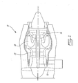
- Fig.1 illustrates a gas turbine engine 10 of a type preferably provided for use in subsonic flight, generally comprising in serial flow communication a fan 12 through which ambient air is propelled, a multistage compressor 14 for pressurizing the air, a combustor 16 in which the compressed air is mixed with fuel and ignited for generating an annular stream of hot combustion gases, and a turbine section 18 for extracting energy from the combustion gases.
- a gas turbine engine 10 of a type preferably provided for use in subsonic flight, generally comprising in serial flow communication a fan 12 through which ambient air is propelled, a multistage compressor 14 for pressurizing the air, a combustor 16 in which the compressed air is mixed with fuel and ignited for generating an annular stream of hot combustion gases, and a turbine section 18 for extracting energy from the combustion gases.
- a gas turbine engine 10 of a type preferably provided for use in subsonic flight, generally comprising in serial flow communication a fan 12 through which ambient air is propelled, a multistage compressor 14
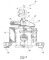
- Figure 2 shows a transport system, shown generally at 20, that is used for transporting the gas turbine engine 10 to and from a build stand, a test cell or a shipping post for example, located within or proximal to a production facility.
- the transport system 20 is adapted to transport the engine 10 while the gas turbine engine 10 is mounted to an engine docking unit (not shown).
- the engine docking unit may comprise pre-dressing equipment and accessories for coupling to the gas turbine engine 10 that are required for testing and evaluation of the gas turbine engine 10. Accordingly, the gas turbine engine 10 may be brought to the test cell in a "pre-dressed" condition in order to minimize the down time of the test cell.
- the transport system 20 comprises a movable support frame 22 having floor engaging members 24.
- An actuated support member 26 is pivotally connected to the support frame 22 in an upright position via a gimbal joint 28 and a pneumatic actuator 30.
- the actuated support member 26 is also movably connected to the support frame 22 via two actuator assemblies 32.
- the transport system 20 also comprises a conventional on-board hydraulic and pneumatic system which is partially shown in Figure 6 and is used to power the various actuators on the transport system 20.
- An upper portion of the support member 26 comprises a male mounting surface 34 which is adapted to mate to a counterpart mounting surface on the engine docking unit and is used to removably secure the engine docking unit to the transport system 20 in a single action.
- the male mounting comprises a cylindrical portion 36 and a tapered portion 38.
- the tapered portion 38 has an upper circular cross-section 40 and a lower square cross-section 42.
- the lower square cross-section 42 of the tapered portion 38 serves as preventing rotation of the engine docking unit relative to the support member 26, and, therefore any non-circular cross-section such as oval or polygonal could also be used.
- An abutment 27 is provided on the surface of the square cross-section portion 42 for supporting the docking unit against gravity.
- the top surface of the support member 26 could also offer an arresting or seating surface on which the end wall of the socket of the engine docking unit could rest.
- the top surface of the support member 26 is occupied by a reflector (not shown).
- the reflector is used to trigger a laser sensor (not shown) on the test cell side.
- the sensor is for fool proofing the installation process.
- the docking unit can be readily disengaged from the support member 26 in a single operation by axially displacing the docking unit in an upward direction.
- the transport system 20 also comprises brackets 44 affixed to each floor engaging member 24 to improve the safety when moving the equipment with a motorized lift truck.
- These lift trucks typically have narrow sliding forks, which if not properly secured could slid inboard and allow the transport unit to tip off the forks.
- the brackets 44 increase the width of the lifting surfaces to prevent this possibility. When using a manual pallet lifter this cannot occur, the fork being non-sliding/ non adjustable.
- the transport system 20 can be inserted with a pallet truck on all four sides of the base. This is very convenient in small floor space area and sides, for moving engines fitted with intake and exhaust ducts. As shown in Fig.
- lateral openings 45 are defined in the outboard side of the floor engaging members 24 for receiving the forks of the lift truck, the pallet lifter or the like, thereby allowing the transport system 20 to be laterally engaged. Similar openings are provided at the rear of the base of the transport system 20.
- the transport system 20 also has a handle 46 affixed to the support frame 22 that can be used for manoeuvring the transport system 20 during taxiing.
- a shelf 48 and storage boxes 50 for storing fasteners, spare components, sensors or the like associated with the testing or operation of the gas turbine engine 10 are also provided.
- the transport system 20 further includes an electrical control box 52 which is used to house a power supply such as a battery (not shown) and various control circuits such as a conventional programmable logic controller (PLC) (not shown) that are associated with the control and operation of the hydraulic and pneumatic system and the various actuators incorporated in the transport system 20.
- PLC programmable logic controller
- a touch screen user interface 54 is also provided to interface with the PLC and facilitate the operation of the transport system 20.
- levelling feet 56 are provided on the floor engaging members 24 of the transport system 20.
- the levelling feet 56 are used to move the transport system 20 up and down in the P direction as shown in Figure 6 when the transport system 20 is stationary.
- the levelling feet 56 are powered by the on-board hydraulic system.
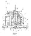
- Figure 3 shows the layout of the levelling feet 56 in relation to the floor engaging members 24.
- Figure 3 also shows the configuration of the two actuator assemblies 32 that are pivotally connected to the support member 26 and are used to cause rotation of the support member 26 about the gimbal joint 28.
- Figure 4 shows the actuator assembly 32 that is used to push and pull the support member 26 along an X axis as shown in Figure 6 . This produces a rotational movement of the support member 26 from the upright position about a Y axis as shown by the arrow RX in Figures 4 and 6 .
- Figure 5 shows the actuator assembly 32 that is used to push and pull the support member 26 along the Y axis as shown in Figure 6 . This produces a rotational movement of the support member 26 from the upright position about the X axis as shown by the arrow RY in Figures 5 and 6 .
- FIG. 7 is a partial cross-sectional view along line 7-7 of Figure 3 and shows details of the support member 26 connected to the gimbal joint 28 and the pneumatic actuator 30.
- the gimbal joint 28 comprises a gimbal 58 and a trunnion 60.
- a lower portion of the support member 26 is pivotally connected to the gimbal 58 at pivot point 62 to permit rotation of the support member 26 about the X axis RY.
- the gimbal 58 is in turn pivotally connected to the trunnion 60 to permit rotation of the support member 26 about the Y axis RX.
- the trunnion 60 is affixed to a casing 64 which is movable along the Z axis within the support frame 22.
- the pneumatic actuator 30 is connected between a bottom side of the casing 64 and the support frame 22 at anchor point 66.
- the pneumatic actuator 30 provides support for the casing 64 together with the support member 26 and also causes the casing 64 and the support member 26 to translate upwardly and downwardly along the Z axis.
- parallel rails 70 are provided on each side of the casing 64 to guide the motion of the casing 64 along the Z axis.
- the rails 70 have a C-shape profile and are adapted to receive and move against bearing members 72 which are affixed to the support frame.
- a load cell 74 is also connected in series within the load string of the pneumatic actuator 30 and is used to measure a reaction force on the support member 26 along the Z axis.
- the pneumatic actuator 30 also provides a pneumatic suspension for the support member 26 and dampens any transportation shocks.
- the pneumatic actuator 30 further provides resilience for engaging the engine docking unit to static structures such as a test cell.
- Figure 10 shows a cross-sectional view of one of the floor engaging members 24 and shows ball casters 76.
- Two ball casters 76 are provided at opposed end portions of each floor engaging member 24 and can be used to taxi the transport system 20 along relatively smooth floor surfaces.
- the ball casters 76 allow easy movement in all direction with equal resistance.
- the ball casters 76 can also ride within a guide rail (not shown) provided in a test cell for example and allow more precise positional adjustments of the transport system 20.
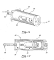
- FIGS 11 and 12 show details of one of the two actuator assemblies 32 that are used to cause the support member 26 to rotate about the X and Y axes.
- Each actuator assembly 32 comprises an actuator such as a hydraulic cylinder 78 and a load cell 74 that are housed within housing 80.
- the housing 80 is affixed to the support frame 22.
- the hydraulic cylinder 78 is operatively connected between the housing 80 and the support member 26.
- the hydraulic cylinder 78 is connected to the housing via a spherical bearing 82 and to the support member 26 via a rod end bearing 84.
- the load cell 74 is connected in series within the load string of the hydraulic cylinder 78 and is used to measure the reaction force on the support member 26.
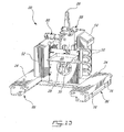
- Figures 13-15 show a transport system 20 according to another embodiment; in this embodiment the two floor engaging members 24 additionally comprise a bearing plate 86.
- the bearing plate 86 is rotatably attached to the floor engaging members 24.
- the floor engaging members 24 have ball casters 76 that are in contact with the inside surface of the bearing plate 86.
- the inside surface of the bearing plate 86 provides a relatively smooth surface for the ball casters 76 on which to ride.
- the ball casters 76 allow the entire support frame 22 to be moved and rotated within a limited range relative to the bearing plate 86.
- the bearing plate 86 is especially useful when the surface on which the transport system 20 is placed is relatively rough and minor positional adjustments are necessary.
- Each manual actuator assembly 88 comprises a stationary housing portion 90 that is affixed to the support frame 22, a rotatable housing portion 92, a load string 94 and a load cell 74.
- the rotatable housing portion 92 is threadingly engaged to the stationary housing portion 90 at a threaded interface 96 to form a screw-type linear actuator.
- the load string 94 is connected between the rotatable housing portion 92 and the support member 26.
- the load string 94 is rotatably connected to the rotatable housing portion 92 and is connected to the support member 26 via the rod end bearing 84.
- the load cell 74 is connected in series within the load string 94 of and is used to measure the reaction force on the support member 26.
- the rotatable housing portion 92 comprises a square socket 98 to which a ratchet 100 having a square drive can be coupled.
- the ratchet 100 can be used to turn the rotatable housing portion 92 relative to the stationary housing portion 90. Due to the threaded interface between the rotatable housing portion 92 and the stationary housing portion 90, the relative rotation causes the rotatable housing portion 92 to either move away or towards the stationary housing portion 90 depending on the direction of rotation. This in turns causes the load string 94 to either push or pull the support member 26.
- the transport system 20 may be used to transport the gas turbine engine 10 mounted to an engine docking unit from a build stand where gas turbine engine 10 is assembled for example, to a testing facility for a pass-off test prior to shipping the gas turbine engine 10 to a customer.
- the engine docking unit may comprise pre-dressing equipment and accessories for coupling to the gas turbine engine 10 that are required for testing and evaluation of the gas turbine engine 10. Accordingly, the engine docking system may be used to interface the gas turbine engine 10 directly to the test cell.
- the engine docking unit may also comprise engine mounts to which the gas turbine engine 10 is to be secured.
- the transport system 20 greatly facilitates the task of transferring the gas turbine engine 10 from the build stand to the engine docking unit.
- the actuated support member 26 of the transport system 20 allows the engine docking unit to be precisely brought in proximity to the gas turbine engine 10 on the build stand and align the various pre-dressing equipment and engine mounts to their counterparts on the gas turbine engine 10. At this point, an operator can simply and safely make all the necessary connections between the gas turbine engine 10 and the engine docking unit. Once the gas turbine engine 10 has been secured to the engine docking unit, the gas turbine engine 10 can safely be unfastened from the build stand.
- the transport system 20 can then be taxied to the testing facility using a floor transport system such as a pallet lifter or using the ball casters 76.
- actuated support member 26 allows the engine docking unit together with the gas turbine engine 10 to be precisely manipulated so as to allow the engine docking unit to be docked to the testing cell together with the engine.
- the PLC is adapted to control the hydraulic and pneumatic actuators on the transport system 20 via the touch screen user interface 52.
- the various load cells 74 are also interfaced to the PLC to inform the operator of the reaction forces on the support member 26 so that the operator can avoid actuating the support member 26 in an unsafe manner.
- the hydraulic actuator assemblies 32 it is possible to provide means of limiting the applied forces so as to prevent accidental overloading of turbine engine components during engine transfers. It is also possible for example to verify during engine transfer that the weight of the gas turbine engine 10 is entirely supported by the receiving structure such as the test cell before safely unfastening the gas turbine engine 10 from the transport system 20.
- the support member 26 can be actuated to release the load at the attachment points, to thereby permit safe transfer from and to the transport system.
- a load monitoring system as provided by the load cells and the PLC or any other suitable load monitoring elements allows the operator to know the magnitude or direction of the loads at the connecting points and, thus, provide guidance as to how the actuator must be operated in order to permit the transfer of the engine.
- the engine is typically connected to a build stand with two side mounts. These mounts can be provided in the form of a lug and yoke arrangement connected with quick release pins. To enable the pins removal, during the engine transfer process, the shear loads must be removed from the pins. The same applies in the transfer from the transport system to the engine testing stand, and shipping undressing posts.
- a typical movement envelope of the tip of the support member 26 would be about ⁇ 50 mm (2 inches) along the X axis, +0 to -330 mm (+0 to -13 inches) along the Y axis, from the upright position, and, about ⁇ 50 mm (2 inches) along the Z axis.
- The-Y axis being in a rearward direction as shown in Figure 6 .
- the transport system 20 could also be adapted to enable other suitable ranges of motion depending on the application.
- the male mounting surface 34 on the support member 26 could be replaced instead by a female mounting surface adapted to mount to a counterpart male mounting surface on the engine docking unit.
- the support member 26 could have two male mounting surfaces arranged in a fork configuration that could be used instead of a tapered portion 38 of varying cross section. The fork configuration would prevent relative rotation of the engine docking unit relative to the support member 26. It is clear that such arrangements would evidently produce the same "single action" securing arrangement of the present configuration.
- the engine docking unit that is used to mount the gas engine turbine 10 may be any type of framework that is suitable to structurally interface the engine to the movable support frame 22.
- the examples described above comprises engine pre-dressing equipment but simpler configurations would also work.
- the gimbal joint 28 provides pivotal movement of the support member 26 in multiple directions. Accordingly other types of joints providing pivotal movement of the support member 26 about at least two axes could also be used such as for example two separate pivot joints, a ball joint or a universal joint and would be within the scope of the present invention.
Landscapes
- Engineering & Computer Science (AREA)
- Transportation (AREA)
- Manufacturing & Machinery (AREA)
- Aviation & Aerospace Engineering (AREA)
- Testing Of Engines (AREA)
- Agricultural Machines (AREA)
Applications Claiming Priority (1)
| Application Number | Priority Date | Filing Date | Title |
|---|---|---|---|
| US11/755,833 US8220769B2 (en) | 2007-05-31 | 2007-05-31 | System for transporting a gas turbine engine |
Publications (2)
| Publication Number | Publication Date |
|---|---|
| EP1997733A2 true EP1997733A2 (fr) | 2008-12-03 |
| EP1997733A3 EP1997733A3 (fr) | 2011-04-27 |
Family
ID=39689405
Family Applications (1)
| Application Number | Title | Priority Date | Filing Date |
|---|---|---|---|
| EP08251884A Withdrawn EP1997733A3 (fr) | 2007-05-31 | 2008-05-30 | Système de transport de moteur de turbine à gaz |
Country Status (4)
| Country | Link |
|---|---|
| US (1) | US8220769B2 (fr) |
| EP (1) | EP1997733A3 (fr) |
| CA (1) | CA2688573C (fr) |
| WO (1) | WO2008144885A1 (fr) |
Cited By (2)
| Publication number | Priority date | Publication date | Assignee | Title |
|---|---|---|---|---|
| CN104647246A (zh) * | 2015-02-11 | 2015-05-27 | 西北工业大学 | 双旋转坐标数控调姿平台 |
| CN110174082A (zh) * | 2019-06-03 | 2019-08-27 | 西安飞机工业(集团)有限责任公司 | 一种可重构定位系统及定位方法 |
Families Citing this family (11)
| Publication number | Priority date | Publication date | Assignee | Title |
|---|---|---|---|---|
| US7735363B2 (en) * | 2007-06-20 | 2010-06-15 | Pratt & Whitney Canada Corp. | Aircraft engine pre-dressing unit for testing facility |
| US7963542B2 (en) * | 2008-08-29 | 2011-06-21 | Solar Turbines Incorporated | Modular cart for a gas turbine engine |
| DE102011007705A1 (de) * | 2011-04-19 | 2012-11-08 | Rolls-Royce Deutschland Ltd & Co Kg | Verfahren und Vorrichtung zum Oberflächenverfestigen und/oder -glätten eines integralbeschaufelten Rotorbereiches eines Strahltriebwerkes |
| US9228451B2 (en) | 2011-05-03 | 2016-01-05 | Pratt & Whitney Canada Corp. | Gas turbine engine module adapter to a carrier |
| DE102014200760A1 (de) * | 2014-01-17 | 2015-07-23 | Siemens Aktiengesellschaft | Läuferschwenksystem |
| SG10201504689WA (en) | 2014-06-13 | 2016-01-28 | United Technologies Corp | Gas turbine engine assembly method and system |
| US10221724B2 (en) | 2015-10-15 | 2019-03-05 | United Technologies Corporation | Horizontal engine build stand |
| US9796505B1 (en) | 2016-04-01 | 2017-10-24 | United Technologies Corporation | Billet support fingers for palletization |
| KR102288273B1 (ko) * | 2019-12-30 | 2021-08-10 | 한국항공우주연구원 | 짐벌마운트 시험장치 |
| US11460373B2 (en) | 2020-09-04 | 2022-10-04 | Pratt & Whitney Canada Corp. | Portable test stand for aircraft engines |
| CN113029576B (zh) * | 2021-03-23 | 2022-04-19 | 中国空气动力研究与发展中心空天技术研究所 | 一种平面叶栅亚声速试验装置中喷管与试验段联调方法 |
Family Cites Families (30)
| Publication number | Priority date | Publication date | Assignee | Title |
|---|---|---|---|---|
| US1237372A (en) | 1916-10-14 | 1917-08-21 | James B Newton | Shock-absorber for automobiles or other vehicles. |
| US2825477A (en) | 1953-09-04 | 1958-03-04 | Henry M Ross | Engine work stand and method of using the same |
| US3087630A (en) | 1961-02-10 | 1963-04-30 | Karnow Paul | Omnidirectional manipulator |
| US3759091A (en) | 1971-07-02 | 1973-09-18 | Gen Electric | Engine inlet distortion testing apparatus |
| US4402108A (en) | 1981-02-17 | 1983-09-06 | Pannwitz Hans U | Reduced static castor |
| FR2628670B1 (fr) | 1988-03-21 | 1990-08-17 | Inst Nat Rech Inf Automat | Dispositif articule, notamment utilisable dans le domaine de la robotique |
| US4996738A (en) | 1990-01-31 | 1991-03-05 | Salustiano Tifre | Free wheel caster |
| FR2664051B1 (fr) | 1990-06-27 | 1993-12-24 | Snecma | Balance de mesure de la poussee d'un turbo reacteur. |
| US5451134A (en) | 1991-10-22 | 1995-09-19 | Bryfogle; Mark D. | Material handling devices and controllers |
| NZ241415A (en) | 1992-01-27 | 1995-04-27 | Air New Zealand Ltd | Gas turbine engine transporting frames |
| US5211526A (en) | 1992-02-28 | 1993-05-18 | Larry Robinette | Mobile crane |
| US5259234A (en) | 1992-03-09 | 1993-11-09 | General Electric Company | Calibration system for air metering bellmouths |
| ES2097395T3 (es) * | 1992-06-22 | 1997-04-01 | Bayne Machine Works Inc | Elevador de cubos para elevar e inclinar un cubo. |
| US5396791A (en) | 1993-08-13 | 1995-03-14 | General Electric Company | Engine testing mounting adaptor |
| US5575607A (en) | 1994-11-02 | 1996-11-19 | United Technologies Corporation | Jet engine transport vehicle lift system and a build cell |
| US5816367A (en) | 1995-11-30 | 1998-10-06 | Stanley Aviation Corporation | Jet aircraft engine transport apparatus |
| US5722512A (en) | 1995-11-30 | 1998-03-03 | Stanley Aviation Corporation | Jet aircraft engine shipping stand |
| US5833424A (en) | 1997-09-23 | 1998-11-10 | Bales; Jerry L. | Round hay bale lifter |
| US6092621A (en) | 1999-06-29 | 2000-07-25 | General Electric Company | Methods and apparatus for suppressing engine test cell howl |
| US6276665B1 (en) | 1999-07-27 | 2001-08-21 | Sunex International, Inc. | Mobile floor crane |
| US20010026756A1 (en) * | 2000-01-28 | 2001-10-04 | Mortimore Dennis L. | Lift for a motorized vehicle or the like |
| US6485247B1 (en) * | 2000-09-28 | 2002-11-26 | The Boeing Company | Engine uplift loader |
| US6546616B2 (en) | 2000-12-15 | 2003-04-15 | Bell Helicopter Textron Inc. | Six-axis alignment and installation tool |
| US20030063968A1 (en) * | 2001-10-01 | 2003-04-03 | Zaun Richard D. | Apparatus for transporting and filling freight containers |
| US20030131444A1 (en) | 2002-01-04 | 2003-07-17 | Minoru Koguchi | Caster with ball |
| GB2384058B (en) | 2002-01-15 | 2005-11-30 | Rolls Royce Plc | Thrust correction |
| WO2005037163A2 (fr) * | 2003-10-13 | 2005-04-28 | Hill-Rom Services, Inc. | Support d'equipement de soins, pouvant etre transfere,pour patients |
| US7103952B2 (en) * | 2004-03-12 | 2006-09-12 | The Boeing Company | Engine loader and transporter apparatus and methods |
| US7402130B1 (en) * | 2006-09-29 | 2008-07-22 | Roll Systems, Inc. | System and method for folding and handling stacks of continuous web |
| US7735363B2 (en) * | 2007-06-20 | 2010-06-15 | Pratt & Whitney Canada Corp. | Aircraft engine pre-dressing unit for testing facility |
-
2007
- 2007-05-31 US US11/755,833 patent/US8220769B2/en active Active
-
2008
- 2008-05-16 CA CA2688573A patent/CA2688573C/fr active Active
- 2008-05-16 WO PCT/CA2008/000948 patent/WO2008144885A1/fr not_active Ceased
- 2008-05-30 EP EP08251884A patent/EP1997733A3/fr not_active Withdrawn
Cited By (3)
| Publication number | Priority date | Publication date | Assignee | Title |
|---|---|---|---|---|
| CN104647246A (zh) * | 2015-02-11 | 2015-05-27 | 西北工业大学 | 双旋转坐标数控调姿平台 |
| CN104647246B (zh) * | 2015-02-11 | 2017-01-11 | 西北工业大学 | 双旋转坐标数控调姿平台 |
| CN110174082A (zh) * | 2019-06-03 | 2019-08-27 | 西安飞机工业(集团)有限责任公司 | 一种可重构定位系统及定位方法 |
Also Published As
| Publication number | Publication date |
|---|---|
| US20080296469A1 (en) | 2008-12-04 |
| US8220769B2 (en) | 2012-07-17 |
| CA2688573A1 (fr) | 2008-12-04 |
| EP1997733A3 (fr) | 2011-04-27 |
| CA2688573C (fr) | 2015-12-15 |
| WO2008144885A1 (fr) | 2008-12-04 |
Similar Documents
| Publication | Publication Date | Title |
|---|---|---|
| CA2688573C (fr) | Systeme de transport d'une turbine a gaz | |
| US6546616B2 (en) | Six-axis alignment and installation tool | |
| JP5931893B2 (ja) | エンジン搭載システム | |
| US9249733B2 (en) | Gas turbine engine stand | |
| US5575607A (en) | Jet engine transport vehicle lift system and a build cell | |
| US7103952B2 (en) | Engine loader and transporter apparatus and methods | |
| US11506087B2 (en) | Gas turbine engine maintenance stand | |
| EP1991462B1 (fr) | Outil de transport | |
| US11377332B2 (en) | Movable base and method for transporting equipment | |
| US11713139B2 (en) | Movable carriage system and method for implementing a movable carriage system | |
| CN105035346A (zh) | 模块化支柱系统 | |
| CN110509236B (zh) | 一种工作台 | |
| US7568575B2 (en) | Engine support system | |
| CN121043935A (zh) | 一种用于飞艇吊舱贮存和转运的托举装置及方法 | |
| US5897077A (en) | Quick-change skid landing gear | |
| US8393847B1 (en) | Tank handling apparatus and method | |
| CN217350590U (zh) | 发射单元离线维护平台 | |
| CN223291395U (zh) | 一种叠放式的航空发动机运输托架 | |
| HK1125604B (en) | Transport tool |
Legal Events
| Date | Code | Title | Description |
|---|---|---|---|
| PUAI | Public reference made under article 153(3) epc to a published international application that has entered the european phase |
Free format text: ORIGINAL CODE: 0009012 |
|
| AK | Designated contracting states |
Kind code of ref document: A2 Designated state(s): AT BE BG CH CY CZ DE DK EE ES FI FR GB GR HR HU IE IS IT LI LT LU LV MC MT NL NO PL PT RO SE SI SK TR |
|
| AX | Request for extension of the european patent |
Extension state: AL BA MK RS |
|
| PUAL | Search report despatched |
Free format text: ORIGINAL CODE: 0009013 |
|
| AK | Designated contracting states |
Kind code of ref document: A3 Designated state(s): AT BE BG CH CY CZ DE DK EE ES FI FR GB GR HR HU IE IS IT LI LT LU LV MC MT NL NO PL PT RO SE SI SK TR |
|
| AX | Request for extension of the european patent |
Extension state: AL BA MK RS |
|
| AKY | No designation fees paid | ||
| REG | Reference to a national code |
Ref country code: DE Ref legal event code: R108 |
|
| REG | Reference to a national code |
Ref country code: DE Ref legal event code: R108 Effective date: 20120104 |
|
| STAA | Information on the status of an ep patent application or granted ep patent |
Free format text: STATUS: THE APPLICATION IS DEEMED TO BE WITHDRAWN |
|
| 18D | Application deemed to be withdrawn |
Effective date: 20111028 |