EP1997760B1 - Lagermittel für Schlauchwaren - Google Patents
Lagermittel für Schlauchwaren Download PDFInfo
- Publication number
- EP1997760B1 EP1997760B1 EP08009607A EP08009607A EP1997760B1 EP 1997760 B1 EP1997760 B1 EP 1997760B1 EP 08009607 A EP08009607 A EP 08009607A EP 08009607 A EP08009607 A EP 08009607A EP 1997760 B1 EP1997760 B1 EP 1997760B1
- Authority
- EP
- European Patent Office
- Prior art keywords
- disk
- storage means
- accordance
- tensioning members
- chain
- Prior art date
- Legal status (The legal status is an assumption and is not a legal conclusion. Google has not performed a legal analysis and makes no representation as to the accuracy of the status listed.)
- Not-in-force
Links
- 238000011161 development Methods 0.000 description 3
- 230000018109 developmental process Effects 0.000 description 3
- 230000001360 synchronised effect Effects 0.000 description 3
- 230000006735 deficit Effects 0.000 description 2
- 239000000853 adhesive Substances 0.000 description 1
- 230000001070 adhesive effect Effects 0.000 description 1
- 230000000694 effects Effects 0.000 description 1
- 239000002184 metal Substances 0.000 description 1
- 238000000034 method Methods 0.000 description 1
- 238000012858 packaging process Methods 0.000 description 1
- 238000004804 winding Methods 0.000 description 1
Images

Classifications
-
- B—PERFORMING OPERATIONS; TRANSPORTING
- B65—CONVEYING; PACKING; STORING; HANDLING THIN OR FILAMENTARY MATERIAL
- B65H—HANDLING THIN OR FILAMENTARY MATERIAL, e.g. SHEETS, WEBS, CABLES
- B65H49/00—Unwinding or paying-out filamentary material; Supporting, storing or transporting packages from which filamentary material is to be withdrawn or paid-out
- B65H49/18—Methods or apparatus in which packages rotate
- B65H49/20—Package-supporting devices
- B65H49/30—Swifts or skein holders
-
- B—PERFORMING OPERATIONS; TRANSPORTING
- B65—CONVEYING; PACKING; STORING; HANDLING THIN OR FILAMENTARY MATERIAL
- B65H—HANDLING THIN OR FILAMENTARY MATERIAL, e.g. SHEETS, WEBS, CABLES
- B65H2701/00—Handled material; Storage means
- B65H2701/30—Handled filamentary material
- B65H2701/33—Hollow or hose-like material
Definitions
- the invention relates to a storage means for tubular goods according to claim 1.
- the US 2,990,135 discloses a storage means for tubular goods according to the preamble of claim 1.
- Hose goods are regularly delivered as so-called ring goods. These rings are generally fixed by metal bands or adhesive strips. When loosening this fixing the hose ring loses its stability, whereby the handling is difficult. Especially when making up by the meter, the handling proves to be difficult, since the former hose ring additionally twists during unwinding.
- the invention aims to remedy this situation.
- the invention has for its object to provide a storage means for tubular goods, which allows easy storage and handling of tubular goods.
- this object is solved by the features of claim 1. Due to the arcuate recesses in which the clamping bars are guided, a uniform clamping of the hose ring is made possible. Preferably, the arcuate recesses describe a semicircular arc.
- the clamping bars are each releasably attached to a sprocket releasably. This allows a synchronous movement of the clamping bars along the arcuate recesses.
- the sprockets are connected by a chain. As a result, a uniform drive of the sprockets is effected.
- the sprockets are rotatably mounted on the underside of the disc opposite the spars. As a result, an impairment of the tubular goods is avoided by the sprockets.
- the disc has a center curvature for receiving a bearing flange.
- a bearing flange is provided, in which the disk is rotatably mounted.
- Another sprocket is arranged, which is connected to the chain and over which the chain is driven. This allows a simple synchronous movement of the clamping bars on the disc.
- the sprocket is manually driven by a rotary handle. This allows a quick and easy synchronous adjustment of the clamping bars.
- the rotary handle is releasably connected to the sprocket. This allows the removal of the rotary handle after use. Disturbing effects by the rotary handle in the packaging process by the rotary handle are thereby avoided.
- a circumferential web for protecting the sprockets is arranged on the clamping bars opposite bottom of the disc. As a result, an impairment of the sprockets is counteracted from the outside.
- the bearing means 1 chosen as an exemplary embodiment consists essentially of an upper part 2 and a lower part 3.
- the upper part 2 comprises in the exemplary embodiment a circular disc 21, in which four circular arc-shaped recesses 23 are introduced.
- the recesses 23 each receive a clamping bar 22, which is guided in the respective recess 23.
- the clamping bars 22 are largely cylindrical. At their end facing the disk 21, the clamping bars 22 have a threaded piece 221, which passes through the recess 23.
- sprockets 24 are rotatably mounted on the disc 21.
- the sprockets 24 are provided with an eccentrically arranged threaded bore 241, which is arranged such that it passes through the circular arc of the recess 23 during rotation of the sprocket 24.
- the threaded portion 221 of a clamping spar 22, which passes through the recess 23, screwed By rotation of the clamping member 22 and the threaded part 221 of the clamping member 22 can be clamped against the disc 21, so that a locking of the clamping member 22 is made possible.
- other connection techniques for connecting the clamping beam 22 to the sprocket 24 are possible.
- the sprockets 24 are connected to each other via a chain 25.
- the disc 21 is provided centrally with a curvature 27 for receiving the bearing flange 31 of the lower part 3. Centered in the curvature 27, an axis 28 for rotatably supporting the upper part 2 in the lower part 3 is arranged.
- an adjusting module 26 is furthermore arranged eccentrically as drive means for the sprockets 24 via the chain 25 in the exemplary embodiment.
- the adjustment module 26 consists essentially of a cylindrical piece 260 which passes through the disc 21 in the direction of Disc underside passes and at the end of the height of the sprockets 24 a reduced in diameter relative to the sprockets 24 executed sprocket 261 is arranged.
- a receptacle 262 for a - not shown - rotary handle is inserted into the cylinder piece 260.
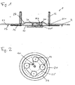
- the chain guide is in Fig. 2 shown.
- the chain is guided in relation to the axis of rotation of the disc 21 to the sprockets 24 outside; the smaller sprocket 261 of the adjustment module 26 is looped around on its inside facing the axis of rotation of the disc 21 of the chain 25.
- a web 29 is circumferentially disposed on the underside of the disc.
- the lower part 3 comprises a bearing flange 31 for receiving the axis 28 of the upper part 2.
- two bearing rings 32 are introduced in the embodiment, wherein a bearing ring as a radial ball bearing and another, the disc 21 facing bearing ring is designed as a tapered roller bearing.
- the bearing rings 32 form an axle receptacle 33 for the axis 28 of the upper part 2.
- bores 34 are introduced for fastening the lower part 3, for example on a shelf.
- the storage means according to the invention can also be used for other winding products, such as cable goods.
- cable goods are mainly supplied as a drum product, which does not provide the initially described problems.
Landscapes
- Warehouses Or Storage Devices (AREA)
- Storage Of Web-Like Or Filamentary Materials (AREA)
- Vending Machines For Individual Products (AREA)
- Manipulator (AREA)
- De-Stacking Of Articles (AREA)
- Tubes (AREA)
Description
- Die Erfindung betrifft ein Lagermittel für Schlauchwaren nach dem Patentanspruch 1.
- Die
US 2,990,135 offenbart ein Lagermittel für Schlauchwaren nach dem Oberbegriff des Anspruchs 1. - Schlauchwaren werden regelmäßig als sog. Ringware geliefert. Diese Ringe sind im Allgemeinen über Metallbänder oder Klebestreifen fixiert. Beim Lösen dieser Fixiermittel verliert der Schlauchring seine Stabilität, wodurch die Handhabung erschwert ist. Insbesondere beim Konfektionieren von Meterware erweist sich die Handhabung als schwierig, da sich der ehemalige Schlauchring beim Abwickeln zusätzlich verwindet.
- Hier will die Erfindung Abhilfe schaffen. Der Erfindung liegt die Aufgabe zugrunde, ein Lagermittel für Schlauchwaren zu schaffen, welches eine einfache Lagerung und Handhabung von Schlauchwaren ermöglicht. Gemäß der Erfindung wird diese Aufgabe durch die Merkmale des Patentanspruchs 1 gelöst. Durch die bogenförmigen Aussparungen, in denen die Spannholme geführt sind, ist ein gleichmäßiges Spannen des Schlauchrings ermöglicht. Bevorzugt beschreiben die bogenförmigen Aussparungen einen Halbkreisbogen.
- Die Spannholme sind jeweils exzentrisch an einem Kettenrad lösbar befestigt. Hierdurch ist eine synchrone Bewegung der Spannholme entlang der bogenförmigen Aussparungen ermöglicht.
- Die Kettenräder sind über eine Kette miteinander verbunden. Hierdurch ist ein gleichmäßiger Antrieb der Kettenräder bewirkt.
- Die Kettenräder sind auf der den Spannholmen entgegengesetzten Unterseite der Scheibe an dieser drehbar befestigt. Hierdurch ist eine Beeinträchtigung der Schlauchwaren durch die Kettenräder vermieden.
- In weiterer Ausgestaltung der Erfindung weist die Scheibe mittig eine Wölbung zur Aufnahme eines Lagerflansches auf. Hierdurch ist eine kompakte Bauhöhe des Lagermittels bewirkt.
- In Weiterbildung der Erfindung ist ein Lagerflansch vorgesehen, in dem die Scheibe drehbar gelagert ist. Hierdurch ist eine einfache Fixierung des Lagermittels beispielsweise auf einem Regalboden ermöglicht.
- Ein weiteres Kettenrad ist angeordnet, das mit der Kette verbunden ist und über das die Kette antreibbar ist. Hierdurch ist eine einfache synchrone Bewegung der Spannholme auf der Scheibe ermöglicht.
- Bevorzugt ist das Kettenrad manuell über einen Drehgriff antreibbar. Hierdurch ist eine schnelle und einfache synchrone Verstellung der Spannholme ermöglicht.
- Vorteilhaft ist der Drehgriff mit dem Kettenrad lösbar verbunden. Hierdurch ist die Entfernung des Drehgriffs nach Gebrauch ermöglicht. Störende Effekte durch den Drehgriff im Konfektionierungsprozess durch den Drehgriff sind hierdurch vermieden.
- In Ausgestaltung der Erfindung ist an der den Spannholmen entgegengesetzten Unterseite der Scheibe ein umlaufender Steg zum Schutz der Kettenräder angeordnet. Hierdurch ist eine Beeinträchtigung der Kettenräder von Außen entgegengewirkt.
- In Weiterbildung der Erfindung sind Mittel zur Arretierung wenigstens eines Spannholmes vorgesehen. Hierdurch ist eine Fixierung des Schlauchgutes ermöglicht.
- Andere Weiterbildungen und Ausgestaltungen der Erfindung sind in den übrigen Unteransprüchen angegeben. Ein Ausführungsbeispiel der Erfindung ist in den Zeichnungen dargestellt und wird nachfolgend im Einzelnen beschrieben. Es zeigen:
- Fig. 1:
- die schematische Darstellung eines Lagermittels für Schlauchwaren;
- Fig. 2:
- die Darstellung des Oberteils des Lagermittels aus
Fig. 1 in der Ansicht von unten; - Fig. 3:
- die Darstellung des Oberteils aus
Fig. 2 in der Ansicht von oben und - Fig. 4:
- die schematische Darstellung der Lagerung des Oberteils in dem Unterteil des Lagermittels.
- Das als Ausführungsbeispiel gewählte Lagermittel 1 besteht im Wesentlichen aus einem Oberteil 2 und einem Unterteil 3.
- Das Oberteil 2 umfasst im Ausführungsbeispiel eine kreisrunde Scheibe 21, in die vier kreisbogenförmige Aussparungen 23 eingebracht sind. Die Aussparungen 23 nehmen jeweils einen Spannholm 22 auf, welcher in der jeweiligen Aussparung 23 geführt ist. Die Spannholme 22 sind weitgehend zylinderförmig ausgeführt. An ihrem der Scheibe 21 zugewandten Ende weisen die Spannholme 22 ein Gewindestück 221 auf, welches durch die Aussparung 23 hindurchtritt.
- An ihrer den Spannholmen 22 gegenüberliegenden Unterseite sind an der Scheibe 21 vier Kettenräder 24 drehbar befestigt. Die Kettenräder 24 sind mit einer exzentrisch angeordneten Gewindebohrung 241 versehen, welche derart angeordnet ist, dass sie bei Rotation des Kettenrades 24 den Kreisbogen der Aussparung 23 durchläuft. In die Gewindebohrung 241 des Kettenrades 24 ist das Gewindestück 221 eines Spannholms 22, das durch die Aussparung 23 hindurchtritt, eingeschraubt. Durch Verdrehung des Spannholms 22 und dessen Gewindestück 221 kann der Spannholm 22 gegen die Scheibe 21 verklemmt werden, so dass eine Arretierung des Spannholms 22 ermöglicht ist. Alternativ sind auch andere Verbindungstechniken zur Verbindung des Spannholms 22 mit dem Kettenrad 24 möglich. Die Kettenräder 24 sind über eine Kette 25 miteinander verbunden.
- Im Ausführungsbeispiel ist die Scheibe 21 mittig mit einer Wölbung 27 zur Aufnahme des Lagerflansches 31 des Unterteils 3 versehen. Zentriert ist in der Wölbung 27 eine Achse 28 zur drehbaren Lagerung des Oberteils 2 in dem Unterteil 3 angeordnet. Im Bereich der Wölbung 27 ist im Ausführungsbeispiel weiterhin exzentrisch ein Verstellmodul 26 als Antriebsmittel für die Kettenräder 24 über die Kette 25 angeordnet. Das Verstellmodul 26 besteht im wesentlichen aus einem Zylinderstück 260, das durch die Scheibe 21 in Richtung der Scheibenunterseite hindurchtritt und an dessen Ende auf Höhe der Kettenräder 24 ein im Durchmesser gegenüber den Kettenrädern 24 verkleinert ausgeführtes Kettenrad 261 angeordnet ist. An seinem dem Kettenrad 261 gegenüberliegenden Ende ist in das Zylinderstück 260 eine Aufnahme 262 für einen - nicht dargestellten - Drehgriff eingebracht. Die Kettenführung ist in
Fig. 2 dargestellt. Dabei ist die Kette in Bezug auf die Drehachse der Scheibe 21 um die Kettenräder 24 außen geführt; das kleinere Kettenrad 261 des Verstellmoduls 26 wird auf seiner der Drehachse der Scheibe 21 zugewandten Innenseite von der Kette 25 umschlungen. Zum Schutz der Kettenräder ist auf der Unterseite der Scheibe 21 umlaufend ein Steg 29 angeordnet. - Das Unterteil 3 umfasst einen Lagerflansch 31 zur Aufnahme der Achse 28 des Oberteils 2. In dem Lagerflansch 31 sind im Ausführungsbeispiel zwei Lagerringe 32 eingebracht, wobei ein Lagerring als Radialkugellager und ein weiterer, der Scheibe 21 zugewandter Lagerring als Kegelrollenlager ausgeführt ist. Die Lagerringe 32 bilden eine Achsaufnahme 33 für die Achse 28 des Oberteils 2. Weiterhin sind in das Unterteil 3 Bohrungen 34 zur Befestigung des Unterteils 3 beispielsweise an einem Regalboden eingebracht.
- Selbstverständlich ist das erfindungsgemäße Lagemittel auch für andere Wickelwaren, wie beispielsweise Kabelwaren einsetzbar. Kabelwaren werden jedoch überwiegend als Trommelware geliefert, wodurch sich die eingangs geschilderte Problematik nicht stellt.
Claims (10)
- Lagermittel (1) für Schlauchwaren, umfassend eine drehbar gelagerte Scheibe (21) zur Aufnahme der Schlauchwaren, die wenigstens drei Spannholme (22) aufnimmt, welche synchron bewegbar auf der Scheibe (21) angeordnet sind, wobei in der Scheibe (21) bogenförmige Aussparungen (23) eingebracht sind, in denen die Spannholme (22) geführt sind, dadurch gekennzeichnet, dass die Spannholme (22) jeweils exzentrisch an einem Kettenrad (24) lösbar befestigt sind, wobei die Kettenräder (24) an der den Spannholmen (22) entgegengesetzten Unterseite der Scheibe (21) an dieser drehbar befestigt und über eine Kette (25) miteinander verbunden sind und wobei ein weiteres Kettenrad (261) angeordnet ist, das mit der Kette (25) verbunden ist und über das die Kette (25) antreibbar ist.
- Lagermittel nach Anspruch 1, dadurch gekennzeichnet, dass die bogenförmigen Aussparungen (23) einen Halbkreisbogen beschreiben.
- Lagermittel nach Anspruch 2, dadurch gekennzeichnet, dass die Scheibe (21) mittig eine Wölbung (27) zur Aufnahme eines Lagerflansches (31) aufweist.
- Lagermittel nach einem der vorgenannten Ansprüche, dadurch gekennzeichnet, dass ein Lagerflansch (31) vorgesehen ist, in dem die Scheibe (21) drehbar gelagert ist.
- Lagermittel nach einem der vorgenannten Ansprüche, dadurch gekennzeichnet, dass das Kettenrad (261) manuell über einen Drehgriff antreibbar ist.
- Lagermittel nach Anspruch 5, dadurch gekennzeichnet, dass der Drehgriff mit dem Kettenrad (261) lösbar verbunden ist.
- Lagermittel nach einem der vorgenannten Ansprüche, dadurch gekennzeichnet, dass an der den Spannholmen (22) entgegengesetzten Unterseite der Scheibe (21) ein umlaufender Steg (29) zum Schutz der Kettenräder (24, 261) angeordnet ist.
- Lagermittel nach einem der vorgenannten Ansprüche, dadurch gekennzeichnet, dass Mittel zur Arretierung wenigstens eines Spannholmes (22) vorgesehen sind.
- Lagermittel nach Anspruch 8, dadurch gekennzeichnet, dass die Arretierung des wenigstens einen Spannholmes (22) durch dessen Verklemmung gegenüber der Scheibe (21) erfolgt.
- Lagermittel nach Anspruch 8, dadurch gekennzeichnet, dass ein arretierbares Verstellmodul (26) vorgesehen ist, wodurch die Spannholme (22) über eine Kette (25) arretierbar sind.
Applications Claiming Priority (1)
| Application Number | Priority Date | Filing Date | Title |
|---|---|---|---|
| DE102007025724A DE102007025724B3 (de) | 2007-06-01 | 2007-06-01 | Lagermittel für Schlauchwaren |
Related Parent Applications (1)
| Application Number | Title | Priority Date | Filing Date |
|---|---|---|---|
| DE102007025724 Previously-Filed-Application | 2007-06-01 |
Publications (2)
| Publication Number | Publication Date |
|---|---|
| EP1997760A1 EP1997760A1 (de) | 2008-12-03 |
| EP1997760B1 true EP1997760B1 (de) | 2010-08-25 |
Family
ID=39732013
Family Applications (1)
| Application Number | Title | Priority Date | Filing Date |
|---|---|---|---|
| EP08009607A Not-in-force EP1997760B1 (de) | 2007-06-01 | 2008-05-27 | Lagermittel für Schlauchwaren |
Country Status (3)
| Country | Link |
|---|---|
| EP (1) | EP1997760B1 (de) |
| AT (1) | ATE478820T1 (de) |
| DE (2) | DE102007025724B3 (de) |
Families Citing this family (4)
| Publication number | Priority date | Publication date | Assignee | Title |
|---|---|---|---|---|
| DE102008059378B3 (de) * | 2007-06-01 | 2010-06-17 | Axel Schnippering | Lagermittel für Schlauchwaren |
| DE102008060323B4 (de) * | 2008-12-03 | 2014-03-27 | Manfred Wanzke | Haspel |
| DE102010045793B4 (de) | 2010-09-17 | 2014-03-27 | Axel Schnippering | Lagermittel für Schlauchwaren |
| DE102010045794B4 (de) | 2010-09-17 | 2013-06-13 | Axel Schnippering | Lagermittel für Schlauchwaren |
Family Cites Families (11)
| Publication number | Priority date | Publication date | Assignee | Title |
|---|---|---|---|---|
| FR615428A (fr) * | 1925-05-28 | 1927-01-07 | Dérouleur extensible et son support universel | |
| US1950492A (en) * | 1931-05-13 | 1934-03-13 | Jr James Holmer | Take in and pay out reel |
| US2229796A (en) * | 1939-07-31 | 1941-01-28 | Carlson Oliver Oscar | Reel |
| FR1023211A (fr) * | 1950-08-10 | 1953-03-16 | Prec Scient & Ind | Tambour dérouleur à diamètre variable |
| FR1069495A (fr) * | 1953-01-08 | 1954-07-08 | Dévidoir pour fils et rubans | |
| US2990135A (en) * | 1959-07-02 | 1961-06-27 | United States Steel Corp | Adjustable pay-off reel |
| DE1474986A1 (de) * | 1964-12-14 | 1970-01-15 | Bruijn Joseph Alphonsus Maria | Haspel fuer Draht- oder Seilspulen od.dgl. |
| BE662160A (de) * | 1965-04-07 | 1965-08-02 | ||
| FR1480066A (fr) * | 1965-05-21 | 1967-05-05 | Dévidoir à accouplement automatique | |
| US4558833A (en) * | 1984-09-10 | 1985-12-17 | Speck F James | Electrical cable reel |
| DE4006527A1 (de) * | 1990-02-22 | 1991-08-29 | Lapp Kg U I | Haspel zum aufwickeln von kabeln, schlaeuchen und dergleichen |
-
2007
- 2007-06-01 DE DE102007025724A patent/DE102007025724B3/de not_active Expired - Fee Related
-
2008
- 2008-05-27 DE DE502008001184T patent/DE502008001184D1/de active Active
- 2008-05-27 EP EP08009607A patent/EP1997760B1/de not_active Not-in-force
- 2008-05-27 AT AT08009607T patent/ATE478820T1/de active
Also Published As
| Publication number | Publication date |
|---|---|
| ATE478820T1 (de) | 2010-09-15 |
| DE502008001184D1 (de) | 2010-10-07 |
| DE102007025724B3 (de) | 2008-11-20 |
| EP1997760A1 (de) | 2008-12-03 |
Similar Documents
| Publication | Publication Date | Title |
|---|---|---|
| DE3042596C2 (de) | Erntemaschine | |
| EP1997760B1 (de) | Lagermittel für Schlauchwaren | |
| DE3734560C2 (de) | ||
| DE10044370C1 (de) | Transportrolle | |
| DE102012020233B4 (de) | Kupplungsanordnung sowie ein Schwerlast-Transportfahrzeug mit einer derartigen Kupplungsanordnung | |
| DE102007023519A1 (de) | Vakuumzylinder für eine Etikettiervorrichtung | |
| EP1477218B1 (de) | Mischflügel mit lösbarem Endstück, Endstück dafür und Vorrichtung zum Mischen mit einem solchen Mischflügel | |
| DE102008008095A1 (de) | Lageranordnung für ein Drehlager | |
| EP0561198B1 (de) | Gurtförderer | |
| DE2635187A1 (de) | Seilaufwickelvorrichtung | |
| DE2135754C3 (de) | Zentrifugalschleuder für das kontinuierliche Einführen von Gegenständen in eine Förderbahn | |
| DE102008059378B3 (de) | Lagermittel für Schlauchwaren | |
| EP0283790B1 (de) | Vorrichtung zum Transportieren und Drehen von Gegenständen | |
| DE102010045794B4 (de) | Lagermittel für Schlauchwaren | |
| EP4077172B1 (de) | Vorrichtung zur behandlung von behältern und ein verfahren zum austauschen von lagerstellen an behälterbehandlungsvorrichtungen | |
| EP0256550B1 (de) | Vortisch an Gefässbehandlungsmachinen | |
| DE102010045793B4 (de) | Lagermittel für Schlauchwaren | |
| DE2523387C2 (de) | Silo-Austragvorrichtung | |
| EP0266447A1 (de) | Rundlaufendes Schneidwerkzeug, insbesondere zum Stranggranulieren von Kunststoffen | |
| DE9316378U1 (de) | Selbstladewagen | |
| DE3415208C2 (de) | ||
| DE29501941U1 (de) | Transportsternrad für Flaschen o.dgl. | |
| DE2825089C3 (de) | Fördertisch, insbesondere für UmschnUningsmaschinen | |
| DE1560611A1 (de) | Verbesserungen an Tragvorrichtungen fuer Aufwickelspulen in Textilmaschinen | |
| DE3128113C2 (de) | Verstellbare Bandübergabe zur Verwendung im untertägigen Grubenbetrieb, mit einer um 360 Grad um einen Mittelpunkt stufenlos drehbaren Schurre |
Legal Events
| Date | Code | Title | Description |
|---|---|---|---|
| PUAI | Public reference made under article 153(3) epc to a published international application that has entered the european phase |
Free format text: ORIGINAL CODE: 0009012 |
|
| AK | Designated contracting states |
Kind code of ref document: A1 Designated state(s): AT BE BG CH CY CZ DE DK EE ES FI FR GB GR HR HU IE IS IT LI LT LU LV MC MT NL NO PL PT RO SE SI SK TR |
|
| AX | Request for extension of the european patent |
Extension state: AL BA MK RS |
|
| 17P | Request for examination filed |
Effective date: 20090424 |
|
| 17Q | First examination report despatched |
Effective date: 20090622 |
|
| AKX | Designation fees paid |
Designated state(s): AT BE BG CH CY CZ DE DK EE ES FI FR GB GR HR HU IE IS IT LI LT LU LV MC MT NL NO PL PT RO SE SI SK TR |
|
| GRAP | Despatch of communication of intention to grant a patent |
Free format text: ORIGINAL CODE: EPIDOSNIGR1 |
|
| GRAC | Information related to communication of intention to grant a patent modified |
Free format text: ORIGINAL CODE: EPIDOSCIGR1 |
|
| GRAS | Grant fee paid |
Free format text: ORIGINAL CODE: EPIDOSNIGR3 |
|
| GRAA | (expected) grant |
Free format text: ORIGINAL CODE: 0009210 |
|
| AK | Designated contracting states |
Kind code of ref document: B1 Designated state(s): AT BE BG CH CY CZ DE DK EE ES FI FR GB GR HR HU IE IS IT LI LT LU LV MC MT NL NO PL PT RO SE SI SK TR |
|
| REG | Reference to a national code |
Ref country code: GB Ref legal event code: FG4D Free format text: NOT ENGLISH |
|
| REG | Reference to a national code |
Ref country code: CH Ref legal event code: EP |
|
| REG | Reference to a national code |
Ref country code: IE Ref legal event code: FG4D Free format text: LANGUAGE OF EP DOCUMENT: GERMAN |
|
| REF | Corresponds to: |
Ref document number: 502008001184 Country of ref document: DE Date of ref document: 20101007 Kind code of ref document: P |
|
| REG | Reference to a national code |
Ref country code: CH Ref legal event code: NV Representative=s name: RIEDERER HASLER & PARTNER PATENTANWAELTE AG |
|
| REG | Reference to a national code |
Ref country code: NL Ref legal event code: T3 |
|
| LTIE | Lt: invalidation of european patent or patent extension |
Effective date: 20100825 |
|
| PG25 | Lapsed in a contracting state [announced via postgrant information from national office to epo] |
Ref country code: NO Free format text: LAPSE BECAUSE OF FAILURE TO SUBMIT A TRANSLATION OF THE DESCRIPTION OR TO PAY THE FEE WITHIN THE PRESCRIBED TIME-LIMIT Effective date: 20101125 Ref country code: FI Free format text: LAPSE BECAUSE OF FAILURE TO SUBMIT A TRANSLATION OF THE DESCRIPTION OR TO PAY THE FEE WITHIN THE PRESCRIBED TIME-LIMIT Effective date: 20100825 Ref country code: LT Free format text: LAPSE BECAUSE OF FAILURE TO SUBMIT A TRANSLATION OF THE DESCRIPTION OR TO PAY THE FEE WITHIN THE PRESCRIBED TIME-LIMIT Effective date: 20100825 |
|
| PG25 | Lapsed in a contracting state [announced via postgrant information from national office to epo] |
Ref country code: BG Free format text: LAPSE BECAUSE OF FAILURE TO SUBMIT A TRANSLATION OF THE DESCRIPTION OR TO PAY THE FEE WITHIN THE PRESCRIBED TIME-LIMIT Effective date: 20101125 Ref country code: CY Free format text: LAPSE BECAUSE OF FAILURE TO SUBMIT A TRANSLATION OF THE DESCRIPTION OR TO PAY THE FEE WITHIN THE PRESCRIBED TIME-LIMIT Effective date: 20100825 Ref country code: HR Free format text: LAPSE BECAUSE OF FAILURE TO SUBMIT A TRANSLATION OF THE DESCRIPTION OR TO PAY THE FEE WITHIN THE PRESCRIBED TIME-LIMIT Effective date: 20100825 Ref country code: IS Free format text: LAPSE BECAUSE OF FAILURE TO SUBMIT A TRANSLATION OF THE DESCRIPTION OR TO PAY THE FEE WITHIN THE PRESCRIBED TIME-LIMIT Effective date: 20101225 Ref country code: PL Free format text: LAPSE BECAUSE OF FAILURE TO SUBMIT A TRANSLATION OF THE DESCRIPTION OR TO PAY THE FEE WITHIN THE PRESCRIBED TIME-LIMIT Effective date: 20100825 Ref country code: SI Free format text: LAPSE BECAUSE OF FAILURE TO SUBMIT A TRANSLATION OF THE DESCRIPTION OR TO PAY THE FEE WITHIN THE PRESCRIBED TIME-LIMIT Effective date: 20100825 |
|
| REG | Reference to a national code |
Ref country code: IE Ref legal event code: FD4D |
|
| PG25 | Lapsed in a contracting state [announced via postgrant information from national office to epo] |
Ref country code: SE Free format text: LAPSE BECAUSE OF FAILURE TO SUBMIT A TRANSLATION OF THE DESCRIPTION OR TO PAY THE FEE WITHIN THE PRESCRIBED TIME-LIMIT Effective date: 20100825 Ref country code: LV Free format text: LAPSE BECAUSE OF FAILURE TO SUBMIT A TRANSLATION OF THE DESCRIPTION OR TO PAY THE FEE WITHIN THE PRESCRIBED TIME-LIMIT Effective date: 20100825 Ref country code: GR Free format text: LAPSE BECAUSE OF FAILURE TO SUBMIT A TRANSLATION OF THE DESCRIPTION OR TO PAY THE FEE WITHIN THE PRESCRIBED TIME-LIMIT Effective date: 20101126 |
|
| PG25 | Lapsed in a contracting state [announced via postgrant information from national office to epo] |
Ref country code: DK Free format text: LAPSE BECAUSE OF FAILURE TO SUBMIT A TRANSLATION OF THE DESCRIPTION OR TO PAY THE FEE WITHIN THE PRESCRIBED TIME-LIMIT Effective date: 20100825 Ref country code: IE Free format text: LAPSE BECAUSE OF FAILURE TO SUBMIT A TRANSLATION OF THE DESCRIPTION OR TO PAY THE FEE WITHIN THE PRESCRIBED TIME-LIMIT Effective date: 20100825 |
|
| PG25 | Lapsed in a contracting state [announced via postgrant information from national office to epo] |
Ref country code: EE Free format text: LAPSE BECAUSE OF FAILURE TO SUBMIT A TRANSLATION OF THE DESCRIPTION OR TO PAY THE FEE WITHIN THE PRESCRIBED TIME-LIMIT Effective date: 20100825 Ref country code: RO Free format text: LAPSE BECAUSE OF FAILURE TO SUBMIT A TRANSLATION OF THE DESCRIPTION OR TO PAY THE FEE WITHIN THE PRESCRIBED TIME-LIMIT Effective date: 20100825 Ref country code: CZ Free format text: LAPSE BECAUSE OF FAILURE TO SUBMIT A TRANSLATION OF THE DESCRIPTION OR TO PAY THE FEE WITHIN THE PRESCRIBED TIME-LIMIT Effective date: 20100825 Ref country code: SK Free format text: LAPSE BECAUSE OF FAILURE TO SUBMIT A TRANSLATION OF THE DESCRIPTION OR TO PAY THE FEE WITHIN THE PRESCRIBED TIME-LIMIT Effective date: 20100825 |
|
| PG25 | Lapsed in a contracting state [announced via postgrant information from national office to epo] |
Ref country code: ES Free format text: LAPSE BECAUSE OF FAILURE TO SUBMIT A TRANSLATION OF THE DESCRIPTION OR TO PAY THE FEE WITHIN THE PRESCRIBED TIME-LIMIT Effective date: 20101206 |
|
| PLBE | No opposition filed within time limit |
Free format text: ORIGINAL CODE: 0009261 |
|
| STAA | Information on the status of an ep patent application or granted ep patent |
Free format text: STATUS: NO OPPOSITION FILED WITHIN TIME LIMIT |
|
| 26N | No opposition filed |
Effective date: 20110526 |
|
| REG | Reference to a national code |
Ref country code: DE Ref legal event code: R097 Ref document number: 502008001184 Country of ref document: DE Effective date: 20110526 |
|
| PG25 | Lapsed in a contracting state [announced via postgrant information from national office to epo] |
Ref country code: MC Free format text: LAPSE BECAUSE OF NON-PAYMENT OF DUE FEES Effective date: 20110531 Ref country code: MT Free format text: LAPSE BECAUSE OF FAILURE TO SUBMIT A TRANSLATION OF THE DESCRIPTION OR TO PAY THE FEE WITHIN THE PRESCRIBED TIME-LIMIT Effective date: 20100825 |
|
| REG | Reference to a national code |
Ref country code: DE Ref legal event code: R119 Ref document number: 502008001184 Country of ref document: DE Effective date: 20111201 |
|
| GBPC | Gb: european patent ceased through non-payment of renewal fee |
Effective date: 20120527 |
|
| PG25 | Lapsed in a contracting state [announced via postgrant information from national office to epo] |
Ref country code: GB Free format text: LAPSE BECAUSE OF NON-PAYMENT OF DUE FEES Effective date: 20120527 |
|
| PG25 | Lapsed in a contracting state [announced via postgrant information from national office to epo] |
Ref country code: DE Free format text: LAPSE BECAUSE OF NON-PAYMENT OF DUE FEES Effective date: 20111201 |
|
| PG25 | Lapsed in a contracting state [announced via postgrant information from national office to epo] |
Ref country code: PT Free format text: LAPSE BECAUSE OF NON-PAYMENT OF DUE FEES Effective date: 20100825 |
|
| PG25 | Lapsed in a contracting state [announced via postgrant information from national office to epo] |
Ref country code: TR Free format text: LAPSE BECAUSE OF FAILURE TO SUBMIT A TRANSLATION OF THE DESCRIPTION OR TO PAY THE FEE WITHIN THE PRESCRIBED TIME-LIMIT Effective date: 20100825 |
|
| PG25 | Lapsed in a contracting state [announced via postgrant information from national office to epo] |
Ref country code: HU Free format text: LAPSE BECAUSE OF FAILURE TO SUBMIT A TRANSLATION OF THE DESCRIPTION OR TO PAY THE FEE WITHIN THE PRESCRIBED TIME-LIMIT Effective date: 20100825 |
|
| REG | Reference to a national code |
Ref country code: FR Ref legal event code: PLFP Year of fee payment: 8 |
|
| PGFP | Annual fee paid to national office [announced via postgrant information from national office to epo] |
Ref country code: LU Payment date: 20150521 Year of fee payment: 8 |
|
| PGFP | Annual fee paid to national office [announced via postgrant information from national office to epo] |
Ref country code: CH Payment date: 20150520 Year of fee payment: 8 |
|
| PGFP | Annual fee paid to national office [announced via postgrant information from national office to epo] |
Ref country code: BE Payment date: 20150518 Year of fee payment: 8 Ref country code: FR Payment date: 20150519 Year of fee payment: 8 Ref country code: IT Payment date: 20150519 Year of fee payment: 8 Ref country code: AT Payment date: 20150520 Year of fee payment: 8 Ref country code: NL Payment date: 20150520 Year of fee payment: 8 |
|
| PG25 | Lapsed in a contracting state [announced via postgrant information from national office to epo] |
Ref country code: BE Free format text: LAPSE BECAUSE OF NON-PAYMENT OF DUE FEES Effective date: 20160531 |
|
| PG25 | Lapsed in a contracting state [announced via postgrant information from national office to epo] |
Ref country code: LU Free format text: LAPSE BECAUSE OF NON-PAYMENT OF DUE FEES Effective date: 20160527 |
|
| REG | Reference to a national code |
Ref country code: CH Ref legal event code: PL |
|
| REG | Reference to a national code |
Ref country code: NL Ref legal event code: MM Effective date: 20160601 |
|
| REG | Reference to a national code |
Ref country code: AT Ref legal event code: MM01 Ref document number: 478820 Country of ref document: AT Kind code of ref document: T Effective date: 20160527 |
|
| PG25 | Lapsed in a contracting state [announced via postgrant information from national office to epo] |
Ref country code: LI Free format text: LAPSE BECAUSE OF NON-PAYMENT OF DUE FEES Effective date: 20160531 Ref country code: CH Free format text: LAPSE BECAUSE OF NON-PAYMENT OF DUE FEES Effective date: 20160531 |
|
| PG25 | Lapsed in a contracting state [announced via postgrant information from national office to epo] |
Ref country code: NL Free format text: LAPSE BECAUSE OF NON-PAYMENT OF DUE FEES Effective date: 20160601 Ref country code: IT Free format text: LAPSE BECAUSE OF NON-PAYMENT OF DUE FEES Effective date: 20160527 Ref country code: AT Free format text: LAPSE BECAUSE OF NON-PAYMENT OF DUE FEES Effective date: 20160527 |
|
| REG | Reference to a national code |
Ref country code: FR Ref legal event code: ST Effective date: 20170131 |
|
| PG25 | Lapsed in a contracting state [announced via postgrant information from national office to epo] |
Ref country code: FR Free format text: LAPSE BECAUSE OF NON-PAYMENT OF DUE FEES Effective date: 20160531 |