EP1997967A1 - Zahnsystem - Google Patents
Zahnsystem Download PDFInfo
- Publication number
- EP1997967A1 EP1997967A1 EP07109464A EP07109464A EP1997967A1 EP 1997967 A1 EP1997967 A1 EP 1997967A1 EP 07109464 A EP07109464 A EP 07109464A EP 07109464 A EP07109464 A EP 07109464A EP 1997967 A1 EP1997967 A1 EP 1997967A1
- Authority
- EP
- European Patent Office
- Prior art keywords
- tooth
- adapter
- flange
- head
- base
- Prior art date
- Legal status (The legal status is an assumption and is not a legal conclusion. Google has not performed a legal analysis and makes no representation as to the accuracy of the status listed.)
- Granted
Links
Images


Classifications
-
- E—FIXED CONSTRUCTIONS
- E02—HYDRAULIC ENGINEERING; FOUNDATIONS; SOIL SHIFTING
- E02F—DREDGING; SOIL-SHIFTING
- E02F9/00—Component parts of dredgers or soil-shifting machines, not restricted to one of the kinds covered by groups E02F3/00 - E02F7/00
- E02F9/28—Small metalwork for digging elements, e.g. teeth scraper bits
- E02F9/2808—Teeth
- E02F9/2816—Mountings therefor
- E02F9/2825—Mountings therefor using adapters
-
- E—FIXED CONSTRUCTIONS
- E02—HYDRAULIC ENGINEERING; FOUNDATIONS; SOIL SHIFTING
- E02F—DREDGING; SOIL-SHIFTING
- E02F9/00—Component parts of dredgers or soil-shifting machines, not restricted to one of the kinds covered by groups E02F3/00 - E02F7/00
- E02F9/28—Small metalwork for digging elements, e.g. teeth scraper bits
- E02F9/2808—Teeth
- E02F9/2858—Teeth characterised by shape
Definitions
- the invention is related to a tooth system for use in an earthmoving device, such as a dredging or mining device, comprising a tooth and an adapter onto which the tooth is mounted in a detachable fashion, said tooth comprising a longitudinally extending tooth web, a longitudinally extending tooth base and a longitudinally extending tooth head at a distance from the tooth base, said tooth base and tooth head also extending transversely with respect to the web, said adapter comprising an adapter base which is to be fixed onto an earthmoving device, such as onto the teeth bars of a draghead, and an adapter head, a longitudinally extending undercut cavity being defined between the adapter base and the adapter head, wherein the tooth base is slidably fitted within the undercut cavity and wherein the adapter head is slidably fitted between the tooth base and the tooth head for mounting or dismounting the tooth with respect to the front end of the adapter, said adapter comprising at least one zone which faces a correspondingly shaped zone of the tooth.
- Such a tooth system is known from WO2005/005737 .
- Said prior art tooth system is aimed at providing a reliable connection between the tooth and the adapter.
- the system should allow for a quick replacement of the tooth.
- the system can for instance be used in connection with dredging operations, in which case a number of adapters, each carrying a tooth, is mounted on the drag head of a dredger.
- dredging operations in which case a number of adapters, each carrying a tooth, is mounted on the drag head of a dredger.
- both the teeth and the adapters are exposed to the influences of the materials which are being cut, such as rock, stones, sand and the like. These materials exert considerable forces on the teeth and also on the adapter, leading to wear of the tooth excavating part of the teeth, which therefore have to be replaced from time to time.
- the adapters also may suffer from considerable wear. This poses a problem in that said adapters in some cases are fixedly connected to e.g. the teeth bars of a draghead, such as by welding. In other cases, the adapters are fixed releasably.
- the object of the invention is therefore to provide a tooth system of the type described before, which provides for a better support of the tooth with respect to its adapter, as well as for a better protection of the adapter against wear.
- This object is achieved in that at least one pair of correspondingly shaped facing zones of the adapter and the tooth comprises a stepped configuration.
- stepped layout of the facing zones represents a stable support for the tooth with respect to the adapter.
- the stepped zones represent separate areas for supporting the tooth, suitable for withstanding forces and bending moments exerted on the tooth.
- separate areas offer the possibility to accommodate any imperfections in the facing surfaces without impairing the stability of the tooth, which imperfections may result from the manufacturing process of the components in question.
- the stepped configuration enables an easy replacement of the tooth with respect to the adapter.
- the stepped configuration may define a wide cavity section and a narrow cavity section of the adapter, whereby the wide cavity section borders the front end of the adapter.
- the stepped configuration may define a thin adapter flange section and a thick adapter flange section, whereby the thin adapter flange section borders the front end of the adapter.
- such stepped configuration comprises several lands and recesses of the pair of facing zones, whereby each time a pair of a land of the one component, and a recess of the other component are facing each other.
- the adapter has at least an adapter recess bordering the front and thereof and at least an adapter land at the end of the adapter recess opposite the front and, in which case the tooth has at least a tooth land opposite the adapter recess and at least a tooth recess opposite the adapter land.
- the recesses may have a larger longitudinal dimension than the corresponding lands.
- the facing recesses will overlap each other over a certain extent, thus providing a gap in the area of the overlap.
- the adapter head comprises opposite adapter flanges which enclose a slit at their facing edges and which delimit the undercut cavity, the web extending through the slit.
- the tooth head faces the adapter flanges.
- the tooth web is positioned in a slit defined between the oppositie adapter flanges, the tooth base comprising tooth base flanges extending on opposite sides of the tooth web, each tooth base flange being positioned opposite a corresponding adapter flange.
- the pairs of a tooth base flange and a facing adapter flange each have facing flange surfaces which are oriented at equal but opposite angles.
- the slanting tooth base flange surfaces each comprise a tooth base flange recess, which tooth flange recess faces a corresponding adapter flange inner land.
- the slanting tooth base surfaces each comprise a tooth base flange land which faces a corresponding adapter flange inner recess.
- the tooth head comprises two opposite tooth head flanges which are on opposite sides of the web.
- the tooth head flanges each comprise a tooth head flange land which faces a corresponding adapter flange outer recess.
- the tooth head flanges each comprise a tooth head flange recess which faces a corresponding adapter flange outer land.
- the tooth comprises a front cover which is known per se.
- said front cover extends transversely with respect to the tooth web and faces the front end of the adapter.
- the front cover of the tooth abuts the front end of the adapter so as to avoid clenching of the tooth with respect to the adapter which would prevent replacement of the tooth.
- a further improvement of the tooth system according to the invention can be obtained in case the tooth head and the front cover are connected to each other, for instance at a sharp angle.
- the combined effect of the interconnected tooth head and front cover provides an advantageous shielding of the areas of the adapter which would otherwise be prone to the abrasive influences of the materials.
- the interconnected tooth head and front cover provide an additional stabilizing effect with respect to the correspondingly shaped adapter, the front of which is snugly surrounded by said combined tooth head and front cover.
- Locking means may be provided which comprise a locking member positioned at an end of the undercut cavity of the adapter, and a locking part at the tooth base end facing the locking member.
- the locking member and the front cover are at opposite ends of the adapter.
- the undercut cavity of the adapter may be tapered from a relatively wide front end to a relatively narrow back end, the tooth base having a corresponding taper.
- the front cover is at the relatively wide front end of the adapter and the locking element is at or near the relatively narrow back end of the adapter.
- the tooth head covers the outwardly facing surfaces of the adapter to a large extent, which means that the adapter is largely shielded from the abrasive influences of the materials which are being cut loose.
- the tooth head itself will of course still be subjected to these wear phenomena, however having regard to the fact that the tooth, of which the to said forms part, is to be replaced from time to time anyway, such wear is quite acceptable.
- the tooth system comprises a tooth 1 connected to the adapter 2.
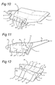
- Said tooth 1 comprises a tooth base 4, as shown in figures 4 , 10 and 11 , as well as a tooth excavating element 5 with a cutting edge 3.
- the tooth comprises a tooth web 6 which extends between the base 4 and the tooth head 15.
- Said tooth head 15 is located opposite the tooth base 4.
- the adapter 2 comprises an adapter base 7 having two opposite upstanding walls 8 which support the adapter head 29.
- the adapter head 29 is provided with facing adapter flanges 9.
- Said adapter base 7, upstanding walls 8 and adapter head 29 with adapter flanges 9 define an undercut cavity 10 which by means of slit 11 opens out at the position of the adapter flanges 9.
- the tooth base 4 of the tooth 1 has been slid into the undercut cavity 10 of the adapter 2.
- the tooth web 6 of the tooth 1 has been accommodated in the slit 11 of the adapter 2.
- the tooth 1 comprises a front cover 12, opposite the front end 13 of the adapter 2, said sliding motion of the tooth 1 with respect to the adapter 2 is limited as soon as the front end 13 and the front cover 12, come into contact.
- the front end 13 of the adapter 2 comprises indentations 31, and the facing surface of the front cover 12 comprises protrusions 30 which are accommodated within said indentations 31.
- locking means 14 are provided for locking the tooth 1 with respect to the adapter 2.
- Said locking means 14 comprises a locking element 32 connected to the adapter 2, as well as a hook 33 forming part of the tooth 1 (see figure 4 ).
- the tooth 1 has been provided with a tooth head 15.
- Said tooth head 15 is connected to the front cover 12, and comprises two tooth head flanges 16, 17 on opposite sides of the web 6.
- the front cover 12 comprises two flanges 18, 19, also on opposite sides of the web 6.
- the tooth head flanges 16, 17 each bear on a corresponding adapter flange 9.
- Said tooth head 15, in combination with the front cover 12, protects the adapter 2 with respect to the abrasive action of the materials which are being cut by the tooth system in question.
- the tooth head flanges 16, 17 each comprise a tooth head flange recess 22 at their rearward end, as well as a tooth head flange land 21 at their forward end adjoining the front cover 12.
- the adapter flanges 9 comprise adapter flange outer lands 26 at their rearward end, as well as adapter flange outer recesses 28 at their forward end.
- the tooth head flanges 16, 17 are stably supported with respect to the corresponding adapter flanges 9 through these pairs of tooth head flange lands 21 and adapter flange outer recesses 28 (see also the cross section of figure 6 ), as well as through the pairs of tooth head flange recesses 22 and adapter flange outer lands 26. (see also the cross-section of figure 8 ).
- the tooth base 4 comprises tooth base flanges 24 at opposite ends of the web 6. These tooth base flanges 24 bear against the inner side of the adapter flanges 9.
- the adapter flanges 9 comprise an adapter flange inner recess 23 (see also the cross-section of figure 8 ) and an adapter flange inner land 20 (see also the cross-section of figure 9 ).
- the tooth base flanges 24 comprise a tooth base flange land 27 and a tooth base flange recess 25.
- the internal cavity 10 of the adapter 2 has a tapering shape, running from a relatively wide cross-section at the front end 13 towards the back end.
- the tooth base 4 has a tapering shape so as to snugly fit within said internal cavity 10.
- a wear plate 35 is positioned on the adapter base 7, as shown in figures 4 , 9 , 15 and 16 , and mounted by means of bolts 34. This wear plate protects the adapter base from wear, and can be easily replaced in case said plate has been worn down by multiple replacements of the tooth.
- the figures 18-20 show an example of the application of the tooth system according to the invention in a suction cutter head.
- the cutter head comprises a suction chamber housing 38 having a suction opening 41 and connected to the suction mouth 40 which is to be connected to a suction tube leading to the bin of a dredging vessel (not shown).
- a pressure conduit 39 is provided for supplying the jet nozzles with pressurized water used in the cutting process.
- the adapters 1 of the tooth system according to the invention are mounted on the suction chamber housing near the suction opening 41, whereby the teeth 2 are positioned in such a way that they can exert a cutting action on the bottom of a body of water while the suction cutter head is dragged (to the right in the figures) over said bottom..
Landscapes
- Engineering & Computer Science (AREA)
- Mining & Mineral Resources (AREA)
- Civil Engineering (AREA)
- General Engineering & Computer Science (AREA)
- Structural Engineering (AREA)
- Component Parts Of Construction Machinery (AREA)
- Instructional Devices (AREA)
- Dental Prosthetics (AREA)
- Grinding Of Cylindrical And Plane Surfaces (AREA)
- Dental Tools And Instruments Or Auxiliary Dental Instruments (AREA)
Priority Applications (10)
| Application Number | Priority Date | Filing Date | Title |
|---|---|---|---|
| EP07109464A EP1997967B1 (de) | 2007-06-01 | 2007-06-01 | Zahnsystem |
| DE602007006446T DE602007006446D1 (de) | 2007-06-01 | 2007-06-01 | Zahnsystem |
| AT07109464T ATE467726T1 (de) | 2007-06-01 | 2007-06-01 | Zahnsystem |
| CA2632359A CA2632359C (en) | 2007-06-01 | 2008-05-27 | Tooth system |
| AU2008202324A AU2008202324B9 (en) | 2007-06-01 | 2008-05-27 | Tooth system |
| MX2008006869A MX2008006869A (es) | 2007-06-01 | 2008-05-28 | Sistema de diente. |
| BRPI0802135-0A BRPI0802135A2 (pt) | 2007-06-01 | 2008-05-29 | sistema de dente |
| KR1020080051000A KR101554736B1 (ko) | 2007-06-01 | 2008-05-30 | 치상돌기 시스템 |
| JP2008144393A JP5252998B2 (ja) | 2007-06-01 | 2008-06-02 | 歯システム |
| US12/131,254 US7690136B2 (en) | 2007-06-01 | 2008-06-02 | Tooth system |
Applications Claiming Priority (1)
| Application Number | Priority Date | Filing Date | Title |
|---|---|---|---|
| EP07109464A EP1997967B1 (de) | 2007-06-01 | 2007-06-01 | Zahnsystem |
Publications (2)
| Publication Number | Publication Date |
|---|---|
| EP1997967A1 true EP1997967A1 (de) | 2008-12-03 |
| EP1997967B1 EP1997967B1 (de) | 2010-05-12 |
Family
ID=38610614
Family Applications (1)
| Application Number | Title | Priority Date | Filing Date |
|---|---|---|---|
| EP07109464A Active EP1997967B1 (de) | 2007-06-01 | 2007-06-01 | Zahnsystem |
Country Status (10)
| Country | Link |
|---|---|
| US (1) | US7690136B2 (de) |
| EP (1) | EP1997967B1 (de) |
| JP (1) | JP5252998B2 (de) |
| KR (1) | KR101554736B1 (de) |
| AT (1) | ATE467726T1 (de) |
| AU (1) | AU2008202324B9 (de) |
| BR (1) | BRPI0802135A2 (de) |
| CA (1) | CA2632359C (de) |
| DE (1) | DE602007006446D1 (de) |
| MX (1) | MX2008006869A (de) |
Cited By (4)
| Publication number | Priority date | Publication date | Assignee | Title |
|---|---|---|---|---|
| NL2004771C2 (en) * | 2010-05-26 | 2011-11-29 | Ihc Holland Ie Bv | Tooth system. |
| WO2012016251A1 (en) * | 2010-07-26 | 2012-02-02 | Krzysztof Ludwik Troszczynski | Wear part system |
| US10745890B2 (en) | 2015-11-13 | 2020-08-18 | Ihc Holland Ie B.V. | Adapter system for cutting tooth |
| SE2330328A1 (en) * | 2023-07-13 | 2025-01-14 | Apt Cutting B V | Wearing-part system |
Families Citing this family (15)
| Publication number | Priority date | Publication date | Assignee | Title |
|---|---|---|---|---|
| US8166678B2 (en) * | 2006-09-01 | 2012-05-01 | Metalogenia, S.A. | Tooth and adaptor for dredging machine |
| BE1018378A3 (nl) * | 2008-12-12 | 2010-09-07 | Dredging Int | Sleepkop voor een sleephopperzuiger en werkwijze voor het baggeren met behulp van deze sleepkop. |
| US8464803B2 (en) | 2010-04-07 | 2013-06-18 | Caterpillar Inc. | DCM having adjustable wear assembly |
| US8869910B2 (en) | 2010-04-07 | 2014-10-28 | Caterpillar Inc. | DCM circle shoe having angled wear insert |
| WO2012142535A2 (en) * | 2011-04-15 | 2012-10-18 | Esco Corporation | Replaceable wear parts for an earth-working roll |
| US8819967B2 (en) | 2012-03-21 | 2014-09-02 | Hensley Industries, Inc. | Adapter stabilization structure for bucket lip |
| CN103174187B (zh) * | 2013-03-19 | 2015-04-15 | 中交天津港航勘察设计研究院有限公司 | 一种挖土机具用卡环齿装置 |
| US20140360061A1 (en) * | 2013-06-10 | 2014-12-11 | Caterpillar Inc. | Wear assembly |
| CA2909065C (en) * | 2013-12-18 | 2017-01-24 | Black Cat Blades Ltd. | Wear member stabilization on excavator lip |
| BR122017028277B1 (pt) * | 2015-02-13 | 2022-05-10 | Black Cat Blades Ltd | Cobertura para proteger um rebordo de um implemento de escavação |
| NL2015672B1 (en) | 2015-10-28 | 2017-05-29 | Ihc Holland Ie Bv | Tooth retaining and locking system. |
| SE542369C2 (sv) * | 2016-05-23 | 2020-04-14 | Combi Wear Parts Ab | Slitdelssystem |
| US11066812B2 (en) | 2017-08-07 | 2021-07-20 | Hensley Industries, Inc. | Bucket lip stabilizer structure |
| US11603647B2 (en) | 2020-01-06 | 2023-03-14 | Pengo Corporation | Excavating tooth assembly for earth-digging equipment |
| WO2021183834A1 (en) * | 2020-03-11 | 2021-09-16 | Bierwith Robert S | Fasteners and fastener systems |
Citations (4)
| Publication number | Priority date | Publication date | Assignee | Title |
|---|---|---|---|---|
| US3345765A (en) * | 1965-05-05 | 1967-10-10 | Petersen Anita E | Reversely bent resilient retainer for digging implement blades |
| GB1333934A (en) | 1971-09-29 | 1973-10-17 | Spencer Sons Ltd Matthias | Mineral mining equipment |
| WO2005005737A1 (en) | 2003-07-11 | 2005-01-20 | Combi Wear Parts Ab | Tooth system |
| US20070044349A1 (en) * | 2005-08-30 | 2007-03-01 | Esco Corporation | Wear assembly for excavating machines |
Family Cites Families (10)
| Publication number | Priority date | Publication date | Assignee | Title |
|---|---|---|---|---|
| US2385395A (en) * | 1944-02-11 | 1945-09-25 | Electric Steel Foundry | Excavating tooth |
| US3919792A (en) * | 1974-11-25 | 1975-11-18 | Esco Corp | Excavating tooth assembly |
| DE3444563A1 (de) * | 1984-12-06 | 1986-06-19 | Lehnhoff Hartstahl GmbH & Co, 7570 Baden-Baden | Baggerzahn-anordnung |
| US5653048A (en) * | 1995-11-06 | 1997-08-05 | Esco Corporation | Wear assembly for a digging edge of an excavator |
| DE69604293T2 (de) * | 1996-07-01 | 2000-03-23 | Metalogenia, S.A. | Kupplungsverbindung für einen Baggerzahn |
| US6145224A (en) * | 1998-11-06 | 2000-11-14 | Caterpillar Inc. | Ground engaging tools for earthworking implements and retainer therefor |
| US6240663B1 (en) * | 2000-09-18 | 2001-06-05 | G. H. Hensley Industries, Incorporated | Streamlined resilient connection system for attaching a wear member to an excavating lip structure |
| US6209238B1 (en) * | 2000-09-18 | 2001-04-03 | Gh Hensley Industries, Inc. | Excavating adapter-to-lip connection apparatus with bottom front-accessible disconnection portion |
| US6729052B2 (en) * | 2001-11-09 | 2004-05-04 | Esco Corporation | Assembly for securing an excavating tooth |
| JP3995158B2 (ja) * | 2003-09-29 | 2007-10-24 | 越後商事株式会社 | バケット用ツース部材の間隙調整体 |
-
2007
- 2007-06-01 AT AT07109464T patent/ATE467726T1/de not_active IP Right Cessation
- 2007-06-01 EP EP07109464A patent/EP1997967B1/de active Active
- 2007-06-01 DE DE602007006446T patent/DE602007006446D1/de not_active Expired - Fee Related
-
2008
- 2008-05-27 AU AU2008202324A patent/AU2008202324B9/en not_active Ceased
- 2008-05-27 CA CA2632359A patent/CA2632359C/en not_active Expired - Fee Related
- 2008-05-28 MX MX2008006869A patent/MX2008006869A/es active IP Right Grant
- 2008-05-29 BR BRPI0802135-0A patent/BRPI0802135A2/pt not_active IP Right Cessation
- 2008-05-30 KR KR1020080051000A patent/KR101554736B1/ko not_active Expired - Fee Related
- 2008-06-02 JP JP2008144393A patent/JP5252998B2/ja not_active Expired - Fee Related
- 2008-06-02 US US12/131,254 patent/US7690136B2/en not_active Expired - Fee Related
Patent Citations (4)
| Publication number | Priority date | Publication date | Assignee | Title |
|---|---|---|---|---|
| US3345765A (en) * | 1965-05-05 | 1967-10-10 | Petersen Anita E | Reversely bent resilient retainer for digging implement blades |
| GB1333934A (en) | 1971-09-29 | 1973-10-17 | Spencer Sons Ltd Matthias | Mineral mining equipment |
| WO2005005737A1 (en) | 2003-07-11 | 2005-01-20 | Combi Wear Parts Ab | Tooth system |
| US20070044349A1 (en) * | 2005-08-30 | 2007-03-01 | Esco Corporation | Wear assembly for excavating machines |
Cited By (8)
| Publication number | Priority date | Publication date | Assignee | Title |
|---|---|---|---|---|
| NL2004771C2 (en) * | 2010-05-26 | 2011-11-29 | Ihc Holland Ie Bv | Tooth system. |
| WO2011149344A1 (en) | 2010-05-26 | 2011-12-01 | Ihc Holland Ie B.V. | Tooth system |
| CN103025969A (zh) * | 2010-05-26 | 2013-04-03 | Ihc荷兰Ie有限公司 | 齿系统 |
| CN103025969B (zh) * | 2010-05-26 | 2016-10-19 | Ihc荷兰Ie有限公司 | 齿系统 |
| WO2012016251A1 (en) * | 2010-07-26 | 2012-02-02 | Krzysztof Ludwik Troszczynski | Wear part system |
| US10745890B2 (en) | 2015-11-13 | 2020-08-18 | Ihc Holland Ie B.V. | Adapter system for cutting tooth |
| SE2330328A1 (en) * | 2023-07-13 | 2025-01-14 | Apt Cutting B V | Wearing-part system |
| WO2025014410A1 (en) * | 2023-07-13 | 2025-01-16 | Combi Wear Parts Ab | Wearing-part system |
Also Published As
| Publication number | Publication date |
|---|---|
| MX2008006869A (es) | 2012-10-03 |
| KR20080106104A (ko) | 2008-12-04 |
| DE602007006446D1 (de) | 2010-06-24 |
| BRPI0802135A2 (pt) | 2009-01-20 |
| AU2008202324A1 (en) | 2008-12-18 |
| AU2008202324B2 (en) | 2014-11-06 |
| JP2008303701A (ja) | 2008-12-18 |
| EP1997967B1 (de) | 2010-05-12 |
| CA2632359A1 (en) | 2008-12-01 |
| CA2632359C (en) | 2015-12-29 |
| ATE467726T1 (de) | 2010-05-15 |
| KR101554736B1 (ko) | 2015-09-21 |
| US20090000159A1 (en) | 2009-01-01 |
| AU2008202324B9 (en) | 2014-11-13 |
| US7690136B2 (en) | 2010-04-06 |
| JP5252998B2 (ja) | 2013-07-31 |
Similar Documents
| Publication | Publication Date | Title |
|---|---|---|
| EP1997967B1 (de) | Zahnsystem | |
| US11788260B2 (en) | Implement ground engaging tip assembly having tip with tapered retention channel | |
| US12123176B2 (en) | Implement tip assembly having tip with support rib | |
| TW202035831A (zh) | 用於土方作業設備的磨損元件 | |
| US11613874B2 (en) | Implement tip assembly having tip with wear indicator | |
| CN101736772B (zh) | 齿系统 |
Legal Events
| Date | Code | Title | Description |
|---|---|---|---|
| PUAI | Public reference made under article 153(3) epc to a published international application that has entered the european phase |
Free format text: ORIGINAL CODE: 0009012 |
|
| AK | Designated contracting states |
Kind code of ref document: A1 Designated state(s): AT BE BG CH CY CZ DE DK EE ES FI FR GB GR HU IE IS IT LI LT LU LV MC MT NL PL PT RO SE SI SK TR |
|
| AX | Request for extension of the european patent |
Extension state: AL BA HR MK RS |
|
| 17P | Request for examination filed |
Effective date: 20090602 |
|
| AKX | Designation fees paid |
Designated state(s): AT BE BG CH CY CZ DE DK EE ES FI FR GB GR HU IE IS IT LI LT LU LV MC MT NL PL PT RO SE SI SK TR |
|
| GRAP | Despatch of communication of intention to grant a patent |
Free format text: ORIGINAL CODE: EPIDOSNIGR1 |
|
| GRAC | Information related to communication of intention to grant a patent modified |
Free format text: ORIGINAL CODE: EPIDOSCIGR1 |
|
| GRAS | Grant fee paid |
Free format text: ORIGINAL CODE: EPIDOSNIGR3 |
|
| GRAA | (expected) grant |
Free format text: ORIGINAL CODE: 0009210 |
|
| AK | Designated contracting states |
Kind code of ref document: B1 Designated state(s): AT BE BG CH CY CZ DE DK EE ES FI FR GB GR HU IE IS IT LI LT LU LV MC MT NL PL PT RO SE SI SK TR |
|
| REG | Reference to a national code |
Ref country code: GB Ref legal event code: FG4D |
|
| REG | Reference to a national code |
Ref country code: CH Ref legal event code: EP |
|
| REG | Reference to a national code |
Ref country code: IE Ref legal event code: FG4D |
|
| REF | Corresponds to: |
Ref document number: 602007006446 Country of ref document: DE Date of ref document: 20100624 Kind code of ref document: P |
|
| REG | Reference to a national code |
Ref country code: NL Ref legal event code: T3 |
|
| LTIE | Lt: invalidation of european patent or patent extension |
Effective date: 20100512 |
|
| PG25 | Lapsed in a contracting state [announced via postgrant information from national office to epo] |
Ref country code: SE Free format text: LAPSE BECAUSE OF FAILURE TO SUBMIT A TRANSLATION OF THE DESCRIPTION OR TO PAY THE FEE WITHIN THE PRESCRIBED TIME-LIMIT Effective date: 20100512 Ref country code: ES Free format text: LAPSE BECAUSE OF FAILURE TO SUBMIT A TRANSLATION OF THE DESCRIPTION OR TO PAY THE FEE WITHIN THE PRESCRIBED TIME-LIMIT Effective date: 20100823 Ref country code: LT Free format text: LAPSE BECAUSE OF FAILURE TO SUBMIT A TRANSLATION OF THE DESCRIPTION OR TO PAY THE FEE WITHIN THE PRESCRIBED TIME-LIMIT Effective date: 20100512 |
|
| PG25 | Lapsed in a contracting state [announced via postgrant information from national office to epo] |
Ref country code: AT Free format text: LAPSE BECAUSE OF FAILURE TO SUBMIT A TRANSLATION OF THE DESCRIPTION OR TO PAY THE FEE WITHIN THE PRESCRIBED TIME-LIMIT Effective date: 20100512 Ref country code: FI Free format text: LAPSE BECAUSE OF FAILURE TO SUBMIT A TRANSLATION OF THE DESCRIPTION OR TO PAY THE FEE WITHIN THE PRESCRIBED TIME-LIMIT Effective date: 20100512 Ref country code: SI Free format text: LAPSE BECAUSE OF FAILURE TO SUBMIT A TRANSLATION OF THE DESCRIPTION OR TO PAY THE FEE WITHIN THE PRESCRIBED TIME-LIMIT Effective date: 20100512 Ref country code: IS Free format text: LAPSE BECAUSE OF FAILURE TO SUBMIT A TRANSLATION OF THE DESCRIPTION OR TO PAY THE FEE WITHIN THE PRESCRIBED TIME-LIMIT Effective date: 20100912 Ref country code: LV Free format text: LAPSE BECAUSE OF FAILURE TO SUBMIT A TRANSLATION OF THE DESCRIPTION OR TO PAY THE FEE WITHIN THE PRESCRIBED TIME-LIMIT Effective date: 20100512 |
|
| PG25 | Lapsed in a contracting state [announced via postgrant information from national office to epo] |
Ref country code: CY Free format text: LAPSE BECAUSE OF FAILURE TO SUBMIT A TRANSLATION OF THE DESCRIPTION OR TO PAY THE FEE WITHIN THE PRESCRIBED TIME-LIMIT Effective date: 20100602 Ref country code: PL Free format text: LAPSE BECAUSE OF FAILURE TO SUBMIT A TRANSLATION OF THE DESCRIPTION OR TO PAY THE FEE WITHIN THE PRESCRIBED TIME-LIMIT Effective date: 20100512 |
|
| PG25 | Lapsed in a contracting state [announced via postgrant information from national office to epo] |
Ref country code: MC Free format text: LAPSE BECAUSE OF NON-PAYMENT OF DUE FEES Effective date: 20100630 Ref country code: DK Free format text: LAPSE BECAUSE OF FAILURE TO SUBMIT A TRANSLATION OF THE DESCRIPTION OR TO PAY THE FEE WITHIN THE PRESCRIBED TIME-LIMIT Effective date: 20100512 Ref country code: EE Free format text: LAPSE BECAUSE OF FAILURE TO SUBMIT A TRANSLATION OF THE DESCRIPTION OR TO PAY THE FEE WITHIN THE PRESCRIBED TIME-LIMIT Effective date: 20100512 Ref country code: PT Free format text: LAPSE BECAUSE OF FAILURE TO SUBMIT A TRANSLATION OF THE DESCRIPTION OR TO PAY THE FEE WITHIN THE PRESCRIBED TIME-LIMIT Effective date: 20100913 |
|
| PG25 | Lapsed in a contracting state [announced via postgrant information from national office to epo] |
Ref country code: SK Free format text: LAPSE BECAUSE OF FAILURE TO SUBMIT A TRANSLATION OF THE DESCRIPTION OR TO PAY THE FEE WITHIN THE PRESCRIBED TIME-LIMIT Effective date: 20100512 Ref country code: RO Free format text: LAPSE BECAUSE OF FAILURE TO SUBMIT A TRANSLATION OF THE DESCRIPTION OR TO PAY THE FEE WITHIN THE PRESCRIBED TIME-LIMIT Effective date: 20100512 Ref country code: CZ Free format text: LAPSE BECAUSE OF FAILURE TO SUBMIT A TRANSLATION OF THE DESCRIPTION OR TO PAY THE FEE WITHIN THE PRESCRIBED TIME-LIMIT Effective date: 20100512 |
|
| PLBE | No opposition filed within time limit |
Free format text: ORIGINAL CODE: 0009261 |
|
| REG | Reference to a national code |
Ref country code: FR Ref legal event code: ST Effective date: 20110228 |
|
| STAA | Information on the status of an ep patent application or granted ep patent |
Free format text: STATUS: NO OPPOSITION FILED WITHIN TIME LIMIT |
|
| PG25 | Lapsed in a contracting state [announced via postgrant information from national office to epo] |
Ref country code: IT Free format text: LAPSE BECAUSE OF FAILURE TO SUBMIT A TRANSLATION OF THE DESCRIPTION OR TO PAY THE FEE WITHIN THE PRESCRIBED TIME-LIMIT Effective date: 20100512 |
|
| 26N | No opposition filed |
Effective date: 20110215 |
|
| PG25 | Lapsed in a contracting state [announced via postgrant information from national office to epo] |
Ref country code: MT Free format text: LAPSE BECAUSE OF FAILURE TO SUBMIT A TRANSLATION OF THE DESCRIPTION OR TO PAY THE FEE WITHIN THE PRESCRIBED TIME-LIMIT Effective date: 20100512 Ref country code: DE Free format text: LAPSE BECAUSE OF NON-PAYMENT OF DUE FEES Effective date: 20110101 Ref country code: GR Free format text: LAPSE BECAUSE OF FAILURE TO SUBMIT A TRANSLATION OF THE DESCRIPTION OR TO PAY THE FEE WITHIN THE PRESCRIBED TIME-LIMIT Effective date: 20100813 Ref country code: IE Free format text: LAPSE BECAUSE OF NON-PAYMENT OF DUE FEES Effective date: 20100601 |
|
| PG25 | Lapsed in a contracting state [announced via postgrant information from national office to epo] |
Ref country code: FR Free format text: LAPSE BECAUSE OF NON-PAYMENT OF DUE FEES Effective date: 20100712 |
|
| REG | Reference to a national code |
Ref country code: CH Ref legal event code: PL |
|
| GBPC | Gb: european patent ceased through non-payment of renewal fee |
Effective date: 20110601 |
|
| PG25 | Lapsed in a contracting state [announced via postgrant information from national office to epo] |
Ref country code: CH Free format text: LAPSE BECAUSE OF NON-PAYMENT OF DUE FEES Effective date: 20110630 Ref country code: LI Free format text: LAPSE BECAUSE OF NON-PAYMENT OF DUE FEES Effective date: 20110630 |
|
| PG25 | Lapsed in a contracting state [announced via postgrant information from national office to epo] |
Ref country code: GB Free format text: LAPSE BECAUSE OF NON-PAYMENT OF DUE FEES Effective date: 20110601 |
|
| PG25 | Lapsed in a contracting state [announced via postgrant information from national office to epo] |
Ref country code: BG Free format text: LAPSE BECAUSE OF FAILURE TO SUBMIT A TRANSLATION OF THE DESCRIPTION OR TO PAY THE FEE WITHIN THE PRESCRIBED TIME-LIMIT Effective date: 20100512 Ref country code: HU Free format text: LAPSE BECAUSE OF FAILURE TO SUBMIT A TRANSLATION OF THE DESCRIPTION OR TO PAY THE FEE WITHIN THE PRESCRIBED TIME-LIMIT Effective date: 20101113 Ref country code: LU Free format text: LAPSE BECAUSE OF NON-PAYMENT OF DUE FEES Effective date: 20100601 |
|
| PG25 | Lapsed in a contracting state [announced via postgrant information from national office to epo] |
Ref country code: TR Free format text: LAPSE BECAUSE OF FAILURE TO SUBMIT A TRANSLATION OF THE DESCRIPTION OR TO PAY THE FEE WITHIN THE PRESCRIBED TIME-LIMIT Effective date: 20100512 |
|
| PG25 | Lapsed in a contracting state [announced via postgrant information from national office to epo] |
Ref country code: BG Free format text: LAPSE BECAUSE OF FAILURE TO SUBMIT A TRANSLATION OF THE DESCRIPTION OR TO PAY THE FEE WITHIN THE PRESCRIBED TIME-LIMIT Effective date: 20100812 |
|
| REG | Reference to a national code |
Ref country code: NL Ref legal event code: RC Free format text: DETAILS LICENCE OR PLEDGE: RIGHT OF PLEDGE, ESTABLISHED, 1E RANG Name of requester: ING BANK N.V. Effective date: 20190826 |
|
| REG | Reference to a national code |
Ref country code: NL Ref legal event code: RC Free format text: DETAILS LICENCE OR PLEDGE: RIGHT OF PLEDGE, ESTABLISHED, 2E PANDRECHT Name of requester: ING BANK N.V. Effective date: 20190903 |
|
| REG | Reference to a national code |
Ref country code: NL Ref legal event code: RC Free format text: DETAILS LICENCE OR PLEDGE: RIGHT OF PLEDGE, ESTABLISHED Name of requester: GLAS TRUST CORPORATION LIMITED Effective date: 20200623 |
|
| REG | Reference to a national code |
Ref country code: NL Ref legal event code: RC Free format text: DETAILS LICENCE OR PLEDGE: RIGHT OF PLEDGE, ESTABLISHED Name of requester: GLAS TRUST CORPORATION LIMITED Effective date: 20230524 |
|
| P01 | Opt-out of the competence of the unified patent court (upc) registered |
Effective date: 20230527 |
|
| PGFP | Annual fee paid to national office [announced via postgrant information from national office to epo] |
Ref country code: BE Payment date: 20250617 Year of fee payment: 19 Ref country code: NL Payment date: 20250618 Year of fee payment: 19 |
|
| REG | Reference to a national code |
Ref country code: NL Ref legal event code: RC Free format text: DETAILS LICENCE OR PLEDGE: RIGHT OF PLEDGE, ESTABLISHED Name of requester: GLAS SAS Effective date: 20250828 |