EP1998026A2 - Ladeeinrichtung - Google Patents
Ladeeinrichtung Download PDFInfo
- Publication number
- EP1998026A2 EP1998026A2 EP08156336A EP08156336A EP1998026A2 EP 1998026 A2 EP1998026 A2 EP 1998026A2 EP 08156336 A EP08156336 A EP 08156336A EP 08156336 A EP08156336 A EP 08156336A EP 1998026 A2 EP1998026 A2 EP 1998026A2
- Authority
- EP
- European Patent Office
- Prior art keywords
- charging device
- guide vanes
- ring member
- outer ring
- inner ring
- Prior art date
- Legal status (The legal status is an assumption and is not a legal conclusion. Google has not performed a legal analysis and makes no representation as to the accuracy of the status listed.)
- Withdrawn
Links
Images



Classifications
-
- F—MECHANICAL ENGINEERING; LIGHTING; HEATING; WEAPONS; BLASTING
- F04—POSITIVE - DISPLACEMENT MACHINES FOR LIQUIDS; PUMPS FOR LIQUIDS OR ELASTIC FLUIDS
- F04D—NON-POSITIVE-DISPLACEMENT PUMPS
- F04D29/00—Details, component parts, or accessories
- F04D29/40—Casings; Connections of working fluid
- F04D29/42—Casings; Connections of working fluid for radial or helico-centrifugal pumps
- F04D29/44—Fluid-guiding means, e.g. diffusers
- F04D29/46—Fluid-guiding means, e.g. diffusers adjustable
- F04D29/462—Fluid-guiding means, e.g. diffusers adjustable especially adapted for elastic fluid pumps
-
- F—MECHANICAL ENGINEERING; LIGHTING; HEATING; WEAPONS; BLASTING
- F01—MACHINES OR ENGINES IN GENERAL; ENGINE PLANTS IN GENERAL; STEAM ENGINES
- F01D—NON-POSITIVE DISPLACEMENT MACHINES OR ENGINES, e.g. STEAM TURBINES
- F01D17/00—Regulating or controlling by varying flow
- F01D17/10—Final actuators
- F01D17/12—Final actuators arranged in stator parts
- F01D17/14—Final actuators arranged in stator parts varying effective cross-sectional area of nozzles or guide conduits
- F01D17/16—Final actuators arranged in stator parts varying effective cross-sectional area of nozzles or guide conduits by means of nozzle vanes
- F01D17/165—Final actuators arranged in stator parts varying effective cross-sectional area of nozzles or guide conduits by means of nozzle vanes for radial flow, i.e. the vanes turning around axes which are essentially parallel to the rotor centre line
-
- F—MECHANICAL ENGINEERING; LIGHTING; HEATING; WEAPONS; BLASTING
- F04—POSITIVE - DISPLACEMENT MACHINES FOR LIQUIDS; PUMPS FOR LIQUIDS OR ELASTIC FLUIDS
- F04D—NON-POSITIVE-DISPLACEMENT PUMPS
- F04D29/00—Details, component parts, or accessories
- F04D29/40—Casings; Connections of working fluid
- F04D29/42—Casings; Connections of working fluid for radial or helico-centrifugal pumps
- F04D29/44—Fluid-guiding means, e.g. diffusers
- F04D29/441—Fluid-guiding means, e.g. diffusers especially adapted for elastic fluid pumps
-
- F—MECHANICAL ENGINEERING; LIGHTING; HEATING; WEAPONS; BLASTING
- F04—POSITIVE - DISPLACEMENT MACHINES FOR LIQUIDS; PUMPS FOR LIQUIDS OR ELASTIC FLUIDS
- F04D—NON-POSITIVE-DISPLACEMENT PUMPS
- F04D29/00—Details, component parts, or accessories
- F04D29/40—Casings; Connections of working fluid
- F04D29/42—Casings; Connections of working fluid for radial or helico-centrifugal pumps
- F04D29/44—Fluid-guiding means, e.g. diffusers
- F04D29/441—Fluid-guiding means, e.g. diffusers especially adapted for elastic fluid pumps
- F04D29/444—Bladed diffusers
-
- F—MECHANICAL ENGINEERING; LIGHTING; HEATING; WEAPONS; BLASTING
- F05—INDEXING SCHEMES RELATING TO ENGINES OR PUMPS IN VARIOUS SUBCLASSES OF CLASSES F01-F04
- F05D—INDEXING SCHEME FOR ASPECTS RELATING TO NON-POSITIVE-DISPLACEMENT MACHINES OR ENGINES, GAS-TURBINES OR JET-PROPULSION PLANTS
- F05D2220/00—Application
- F05D2220/40—Application in turbochargers
-
- F—MECHANICAL ENGINEERING; LIGHTING; HEATING; WEAPONS; BLASTING
- F05—INDEXING SCHEMES RELATING TO ENGINES OR PUMPS IN VARIOUS SUBCLASSES OF CLASSES F01-F04
- F05D—INDEXING SCHEME FOR ASPECTS RELATING TO NON-POSITIVE-DISPLACEMENT MACHINES OR ENGINES, GAS-TURBINES OR JET-PROPULSION PLANTS
- F05D2250/00—Geometry
- F05D2250/50—Inlet or outlet
- F05D2250/52—Outlet
-
- F—MECHANICAL ENGINEERING; LIGHTING; HEATING; WEAPONS; BLASTING
- F05—INDEXING SCHEMES RELATING TO ENGINES OR PUMPS IN VARIOUS SUBCLASSES OF CLASSES F01-F04
- F05D—INDEXING SCHEME FOR ASPECTS RELATING TO NON-POSITIVE-DISPLACEMENT MACHINES OR ENGINES, GAS-TURBINES OR JET-PROPULSION PLANTS
- F05D2260/00—Function
- F05D2260/50—Kinematic linkage, i.e. transmission of position
- F05D2260/56—Kinematic linkage, i.e. transmission of position using cams or eccentrics
-
- Y—GENERAL TAGGING OF NEW TECHNOLOGICAL DEVELOPMENTS; GENERAL TAGGING OF CROSS-SECTIONAL TECHNOLOGIES SPANNING OVER SEVERAL SECTIONS OF THE IPC; TECHNICAL SUBJECTS COVERED BY FORMER USPC CROSS-REFERENCE ART COLLECTIONS [XRACs] AND DIGESTS
- Y02—TECHNOLOGIES OR APPLICATIONS FOR MITIGATION OR ADAPTATION AGAINST CLIMATE CHANGE
- Y02T—CLIMATE CHANGE MITIGATION TECHNOLOGIES RELATED TO TRANSPORTATION
- Y02T10/00—Road transport of goods or passengers
- Y02T10/10—Internal combustion engine [ICE] based vehicles
- Y02T10/12—Improving ICE efficiencies
Definitions
- the present invention relates to a charging device, in particular an exhaust gas turbocharger for a motor vehicle, according to the preamble of claim 1.
- Such a generic charging device is for example from the US 2006/0112690 A1 known.
- a charging device such as an exhaust gas turbocharger
- the charging device increases the pressure with which air can be introduced into the intake tract of the engine, so that more oxygen is available for combustion of a correspondingly larger amount of fuel.
- a charging device also has a so-called diffuser, with which a gas flow generated by a compressor wheel of the charging device slows down and its gas pressure can be increased.
- the diffuser supplied mass air flow to the respective speed or Adjust the load of the engine.
- the compressor wheel of the charger rotates slowly and therefore can not often provide the required boost pressure.
- the air flow leaving the compressor wheel has a radial velocity component which is proportional to an air mass flow and a tangential velocity component which is proportional to a rotational speed of the compressor wheel. The influence of these two speed components allows control of the air mass flow and the pressure and thus a demand-based charge air supply.
- the present invention addresses the problem of providing an improved embodiment of a generic charging device, which in particular allows use over a wide speed range.
- the invention is based on the general idea of arranging between a compressor wheel and a diffuser of a charging device a vane device with different adjustable guide vanes and thereby influence the tangential and radial velocity components of the air flow accelerated by the compressor wheel and indirectly influence the performance of the charging device.
- a flow angle of the air flow directed to a diffuser inlet can be varied, whereby both an air mass flow and a pressure of the air flow are adaptable to certain engine operating conditions.
- the air flow supplied to the internal combustion engine for combustion can therefore be adapted as needed to different load and rotational speed states of the internal combustion engine.
- a high air mass flow is achieved at the same time low pressure by an increased radial velocity component of the compressor air leaving the compressor, while a high pressure and a low air mass flow can be realized by increasing the tangential velocity component of the air flow leaving the compressor.
- the radial velocity component is proportional to the air mass flow and the tangential velocity component is proportional to the speed of the compressor wheel.
- the charging device according to the invention can be used in a significantly enlarged characteristic field in a significantly larger rotational speed range.
- the guide vane means on an outer and a coaxially arranged inner ring member which are rotatable relative to each other with respect to their axes and wherein the adjustable vanes are mounted on the one hand on the inner Ringelelement and on the other hand on the outer ring member such that a rotation of the inner ring element relative to the outer ring member causes an adjustment of the guide vane and thus a change in a flow angle of the air flow.
- the guide vanes are integrally formed with the inner or the outer ring member, in particular they are molded onto one of these ring elements. Since the guide vane device according to the invention is arranged on the air side of the charging device can be used for this plastic, which on the one hand further reduces the manufacturing costs and on the other hand enables modern injection molding techniques special geometries. By injecting the guide vanes on one of the two ring elements, for example, the assembly of the guide vane means can be significantly simplified, whereby installation costs can be saved.
- the guide vanes are formed as separate components, wherein the guide vanes and / or the outer ring member and / or the inner ring member may be formed of plastic or metal.
- a pneumatically, electrically or hydraulically operated Adjusting device for adjusting an associated with the vane device actuator and thus provided for adjusting the guide vanes.
- an electrically operated adjusting device can be produced on the one hand cost-effective and on the other hand enables a high-precision positioning movement, whereby the air flow supplied to the diffuser is particularly precisely adjustable.
- the adjusting device with an engine control, in particular an electronic engine management system is connected and controlled by this, whereby adapted to respective load and speed conditions of the engine air supply can take place and thereby the power of the engine can be increased.
- the guide vanes are expediently rotatable via a first engagement element, for example a pin, on the inner ring element and via a second engagement element, for example likewise a pin, both rotatably and translationally mounted on the outer ring element or vice versa.
- a first engagement element for example a pin
- a second engagement element for example likewise a pin
- this groove can also be arranged on the inner ring member, wherein in both cases, the rotation of the inner ring member relative to the outer ring member causes an adjustment of the vanes, which is particularly advantageous if the outer Ring element is formed as an integral part of the housing of the charging device.
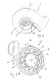
- FIG. 1 has a charging device 1 according to the invention, which is designed here in the manner of an exhaust gas turbocharger for a motor vehicle, a housing 2 and a rotatably mounted in this shaft 3, which at one end carries a compressor 4 and the other end a not shown and an exhaust gas flow turbine wheel.
- the shaft 3 rotates about its shaft axis 5.
- the compressor wheel 4 driven by the exhaust gas flow via the shaft 3 has the task of pressing air for an internal combustion engine, not shown, at elevated pressure into an intake tract of the internal combustion engine.
- this is intended to increase the efficiency of the internal combustion engine, since in a normal piston engine designed as a naturally aspirated engine such a high negative pressure is generated during operation in a high speed range in the intake tract, thereby limiting the performance of the piston engine.
- the charging device 1 the engine per stroke more air at a be supplied according to increased fuel amount, resulting in the increase in performance.
- the compressor wheel 4 conducts an air flow 6 to a diffuser inlet 7 located radially outside the compressor wheel 4 and then to the diffuser 8.
- the air flow 6 is slowed down and thereby increases the air pressure.
- the diffuser thus represents, in principle, the reversal of a nozzle and also serves for the recovery of kinetic energy.
- the charging device 1 since internal combustion engines of motor vehicles over a wide bandwidth with respect to their load and speed should provide a sufficiently high performance, the charging device 1 must be designed such that it always supplies the required for optimal efficiency of the engine air flow to the intake of the engine. Due to the fact that even at low rotational speeds of the internal combustion engine, in which the compressor wheel 4 naturally rotates slower, a sufficiently high boost pressure should be available, the power of the charging device 1 must be decoupled from the rotational speed of the compressor wheel 4.
- the invention proposes to control the air mass flow and the pressure prevailing in it by influencing a radial and a tangential velocity component of the air compressor 4 leaving the compressor wheel 4 at a constant speed of the compressor wheel 4.
- the radial velocity component is proportional to the mass air flow, while the tangential velocity component is proportional to the rotational speed or rotational speed of the compressor wheel 4. This means that at a high air mass flow and a lower pressure at the same time the air flow 6 conveyed by the compressor wheel 4 has a larger radial speed component, while at a higher pressure and a lower air mass flow the air flow 6 leaves the compressor wheel 4 more tangentially.
- a vane device 9 with adjustable guide vanes 10 is provided according to the invention radially adjoining the compressor wheel 4 and arranged in the flow direction in front of the diffuser inlet 7 (cf. Fig. 3 to 7 ). With the aid of these guide vanes 10, a flow angle of the air flow 6 with respect to the diffuser inlet 7 can be adjusted.
- the vane device 9 an outer ring member 11 and a coaxially arranged inner ring member 12 which are mutually rotatable relative to the shaft axis 5.
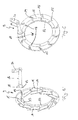
- the adjustable guide vanes 10 are mounted on the one hand on the inner ring member 12 and on the other hand on the outer ring member 11 such that a rotation of the two ring elements 11, 12 relative to each other causes an adjustment of the vanes 10 (see. Fig. 7a and b ).
- the guide vanes 10 are rotatably mounted via a first engagement element 13 on the inner ring member 12 and rotatably mounted via a second engagement member 14 on the outer ring member 11 both rotatable and in a groove 15 (see 4 to 6 ). It is of course also conceivable that the grooves 15 are arranged on the inner ring member 12, while the guide vanes 10 are mounted on the outer ring member 11 only rotatable about their respective engagement member 14.
- an actuator 16 In order to rotate the inner ring member 12 relative to the outer ring member 11, an actuator 16 is provided, which engages via a first pin 17 in a recess 18 on the outer ring member 11 and a second pin 19 in a recess 18 'on the inner ring member 12 , At its end facing away from the pins 17 and 19, the actuator 16 has an actuating lever 20, which is operatively connected to a setting device, not shown, in particular a pneumatically, electrically or hydraulically operated adjusting device. This adjusting device is in turn preferably connected to an engine control, in particular to an engine management system of the motor vehicle.
- a setting device not shown, in particular a pneumatically, electrically or hydraulically operated adjusting device.
- This adjusting device is in turn preferably connected to an engine control, in particular to an engine management system of the motor vehicle.
- the guide vanes 10 have a substantially planar shape, wherein it is also conceivable that the guide vanes 10 are curved in the flow direction of the air flow 6, in particular in the manner of a support surface, are formed.
- the last variant is conceivable for a guide blade device 9 made of plastic.
- the compressor 4 Since the compressor 4 is arranged on the air side of the bearing device 1 and is thus exposed only to a limited temperature load, can be used for the vane 9 and the vanes 10 and for the two ring elements 11 and 12 easily plastic.
- individual components of the vane device 9 may be formed of metal.
- the guide vanes 10 can be made flexible so that they can bend 9, for example, in an adjustment of the vane device.
- they would be according to the Fig. 5 to 7 shown grooves 15 in the outer ring member 11 also formed as a pure recesses in which the pin 14 is rotatably mounted, which, however, do not allow a translational adjustment of the pin 14.
- the vane device 9 can be stored, for example, in that the outer ring element 11 is fastened in a recess provided on the housing 2 of the loading device 1 and not shown. According to a preferred embodiment, it can also be provided that the outer ring element 11 is an integral part of the housing 2 of the charging device 1. Also, contrary to the in the Fig. 7a and b shown embodiments of the guide vanes 10 may be provided that they taper or thicken with respect to their length, that is, that the guide vanes 10 have a different thickness in their length.
- the actuator 16 penetrates the housing 2 and the adjusting lever 20 outside the housing 2 is easily accessible or easily connectable with the adjusting device.
- the actuator 16 only about the outer ring member 11 or the inner ring member 12 with respect to the other ring member 11, 12 can be rotated via the actuator 16 or both ring elements 11, 12 are rotated relative to each other.
- the position of the guide vanes 10 can for example be done via a digital or analog sensor, not shown, which detects, for example, a rotation angle of the actuator 16.
- the illustrated actuator 16 is to be understood purely as an example, so that other lever arrangements for adjusting the vane device 9 are to be encompassed by the invention.
- Fig. 7a and b are now shown two extreme positions of the vane device 9, wherein according to Fig. 7a the vanes 10 have a smaller angle with respect to a tangent to the outer or inner ring member 11, 12, while according to Fig. 7b this angle is significantly larger.
- the air flow 6 experiences a higher tangential velocity
- the vanes 10 according to FIG Fig. 7b experiences a higher radial velocity.
Landscapes
- Engineering & Computer Science (AREA)
- Mechanical Engineering (AREA)
- General Engineering & Computer Science (AREA)
- Supercharger (AREA)
- Structures Of Non-Positive Displacement Pumps (AREA)
Abstract
Description
- Die vorliegende Erfindung betrifft eine Ladeeinrichtung, insbesondere einen Abgasturbolader für ein Kraftfahrzeug, gemäß dem Oberbegriff des Anspruchs 1.
- Eine derartige gattungsgemäße Ladeeinrichtung ist beispielsweise aus der
US 2006/0112690 A1 bekannt. - Eine Ladeeinrichtung, wie beispielsweise ein Abgasturbolader, wird im modernen Kraftfahrzeugbau üblicherweise zur Leistungssteigerung von Kolbenmotoren durch Erhöhung des Luftmengen- und Kraftstoffdurchsatzes pro Arbeitstakt eingesetzt. Dabei erhöht die Ladeeinrichtung den Druck, mit welchem Luft in den Ansaugtrakt des Motors eingeleitet werden kann, so dass mehr Sauerstoff zur Verbrennung einer entsprechend größeren Kraftstoffmenge zur Verfügung steht. Üblicherweise weist eine derartige Ladeeinrichtung auch einen sogenannten Diffusor auf, mit welchem ein von einem Verdichterrad der Ladeeinrichtung erzeugte Gasströmung verlangsamt und deren Gasdruck erhöht werden kann. Da insbesondere Verbrennungsmotoren in Kraftfahrzeugen über eine große Bandbreite an Drehzahl und Last mit hohem Wirkungsgrad arbeiten sollen, ist es erforderlich, den dem Diffusor zugeleiteten Luftmassenstrom an die jeweilige Drehzahl beziehungsweise Last des Motors anpassen zu können. Insbesondere bei geringen Motordrehzahlen dreht sich das Verdichterrad der Ladeeinrichtung entsprechend langsam und kann daher oftmals nicht für den erforderlichen Ladedruck sorgen. Die das Verdichterrad verlassende Luftströmung besitzt eine radiale Geschwindigkeitskomponente, welche proportional zu einem Luftmassenstrom ist und eine tangentiale Geschwindigkeitskomponente, welche proportional zu einer Drehzahl des Verdichterrades ist. Die Beeinflussung dieser beiden Geschwindigkeitskomponenten erlaubt eine Steuerung des Luftmassenstroms und des Drucks und dadurch eine bedarfsgerechte Ladeluftzuführung.
- Die vorliegende Erfindung beschäftigt sich mit dem Problem, eine verbesserte Ausführungsform für eine gattungsgemäße Ladeeinrichtung anzugeben, welche insbesondere einen Einsatz über eine große Drehzahlbreite ermöglicht.
- Dieses Problem wird erfindungsgemäß durch den Gegenstand des unabhängigen Anspruchs 1 gelöst. Vorteilhafte Ausführungsformen sind Gegenstand der abhängigen Ansprüche.
- Die Erfindung beruht auf dem allgemeinen Gedanken, zwischen einem Verdichterrad und einem Diffusor einer Ladeeinrichtung eine Leitschaufeleinrichtung mit verschiedenen, einstellbaren Leitschaufeln anzuordnen und dadurch Einfluss auf die tangentialen und radialen Geschwindigkeitskomponenten der vom Verdichterrad beschleunigten Luftströmung und indirekt damit Einfluss auf die Leistung der Ladeeinrichtung zu nehmen. Über die Leitschaufeleinrichtung mit den verstellbaren Leitschaufeln lässt sich ein Strömungswinkel der einem Diffusoreingang zugeleiteten Luftströmung variieren, wodurch sowohl ein Luftmassenstrom als auch ein Druck der Luftströmung an bestimmte Motorbetriebszustände anpassbar sind. Insbesondere lässt sich somit die dem Verbrennungsmotor zur Verbrennung zugeführte Luftströmung an unterschiedliche Last- und Drehzahlzustände des Verbrennungsmotors bedarfsgerecht anpassen. Beispielsweise wird ein hoher Luftmassenstrom bei gleichzeitig geringem Druck durch eine erhöhte radiale Geschwindigkeitskomponente der das Verdichterrad verlassenden Luftströmung erreicht, während ein hoher Druck und ein geringer Luftmassenstrom durch eine Erhöhung der tangentialen Geschwindigkeitskomponente der das Verdichterrad verlassenden Luftströmung realisierbar ist. Hierbei wird die Erkenntnis genutzt, dass die radiale Geschwindigkeitskomponente proportional zum Luftmassenstrom und die tangentiale Geschwindigkeitskomponente proportional zur Drehzahl des Verdichterrades ist. Dadurch kann die erfindungsgemäße Ladeeinrichtung in einem deutlich vergrößerten Kennfeld in einem deutlich größeren Drehzahlbereich eingesetzt werden.
- Gemäß einer vorteilhaften Weiterbildung der erfindungsgemäßen Lösung weist die Leitschaufeleinrichtung ein äußeres und ein koaxial dazu angeordnetes inneres Ringelement auf, welche bezüglich ihrer Achsen zueinander verdrehbar sind und wobei die verstellbaren Leitschaufeln einerseits am inneren Ringelelement und andererseits am äußeren Ringelement derart gelagert sind, dass eine Verdrehung des inneren Ringelementes relativ zum äußeren Ringelement eine Verstellung der Leitschaufel und damit eine Veränderung eines Abströmwinkels der Luftströmung bewirkt. Durch den Aufbau der Leitschaufeleinrichtung mit einem inneren und einem äußeren Ringelement und dem daran gelagerten Leitschaufeln kann eine konstruktiv einfache und gleichzeitig technisch ausgereifte Lösung präsentiert werden, welche sich insbesondere durch geringe Herstellungskosten einerseits und eine genaue Justierbarkeit andererseits auszeichnet.
- Zweckmäßig sind die Leitschaufeln einteilig mit dem inneren oder dem äußeren Ringelement ausgebildet, insbesondere sind sie an eines dieser Ringelemente angespritzt. Da die erfindungsgemäße Leitschaufeleinrichtung auf der Luftseite der Ladeeinrichtung angeordnet ist, kann für diese Kunststoff zum Einsatz kommen, welcher einerseits die Herstellungskosten weiter reduzieren hilft und andererseits durch moderne Spritzgusstechniken besondere Geometrien ermöglicht. Durch das Anspritzen der Leitschaufeln an eines der beiden Ringelemente lässt sich beispielsweise der Zusammenbau der Leitschaufeleinrichtung deutlich vereinfachen, wodurch Montagekosten eingespart werden können. Selbstverständlich ist alternativ auch denkbar, dass die Leitschaufeln als separate Bauteile ausgebildet sind, wobei die Leitschaufeln und/oder das äußere Ringelement und/oder das innere Ringelement aus Kunststoff oder aus Metall ausgebildet sein können.
- Bei einer weiteren vorteilhaften Weiterbildung der Erfindung ist eine pneumatisch, elektrisch oder hydraulisch betriebene Stelleinrichtung zum Verstellen eines mit der Leitschaufeleinrichtung verbundenen Stellgliedes und damit zum Verstellen der Leitschaufeln vorgesehen. Insbesondere eine elektrisch betriebene Stelleinrichtung lässt sich einerseits kostengünstig herstellen und ermöglicht andererseits eine hochpräzise Stellbewegung, wodurch die dem Diffusor zugeführte Luftströmung besonders exakt einstellbar ist. Denkbar ist hierbei auch, dass die Stelleinrichtung mit einer Motorsteuerung, insbesondere einem elektronischen Motormanagementsystem, verbunden ist und von diesem gesteuert wird, wodurch eine an jeweilige Last- und Drehzahlzustände des Motors angepasste Luftzuführung erfolgen kann und dadurch auch die Leistung des Verbrennungsmotors gesteigert werden kann.
- Zweckmäßig sind die Leitschaufeln über ein erstes Eingriffselement, beispielsweise einen Zapfen, am inneren Ringelement drehbar und über ein zweites Eingriffselement, beispielsweise ebenfalls ein Zapfen, am äußeren Ringelement sowohl drehbar als auch in einer Nut translatorisch verstellbar gelagert oder umgekehrt. Dies bedeutet, dass zur Verstellung der Leitschaufeln das innere Ringelement relativ zum äußeren Ringelement verdreht werden muss, wobei während dieses Verdrehvorganges das zweite Eingriffselement der jeweiligen Leitschaufeln in der am äußeren Ringelement vorgesehenen Nut entlang gleitet. Selbstverständlich kann diese Nut auch am inneren Ringelement angeordnet sein, wobei in beiden Fällen die Verdrehung des inneren Ringelementes relativ zum äußeren Ringelement eine Verstellung der Leitschaufeln bewirkt, was insbesondere dann von großem Vorteil ist, wenn das äußere Ringelement als integraler Bestandteil des Gehäuses der Ladeeinrichtung ausgebildet ist.
- Weitere wichtige Merkmale und Vorteile der Erfindung ergeben sich aus den Unteransprüchen, aus den Zeichnungen und aus der zugehörigen Figurenbeschreibung anhand der Zeichnungen.
- Es versteht sich, dass die vorstehend genannten und die nachstehend noch zu erläuternden Merkmale nicht nur in der jeweils angegebenen Kombination, sondern auch in anderen Kombinationen oder in Alleinstellung verwendbar sind, ohne den Rahmen der vorliegenden Erfindung zu verlassen.
- Bevorzugte Ausführungsbeispiele der Erfindung sind in den Zeichnungen dargestellt und werden in der nachfolgenden Beschreibung näher erläutert, wobei sich gleiche Bezugszeichen auf gleiche oder ähnliche oder funktional gleiche Bauteile beziehen.
- Es zeigen, jeweils schematisch,
- Fig. 1
- einen Längsschnitt durch eine erfindungsgemäße Ladeeinrichtung im Bereich eines Diffusors,
- Fig. 2
- eine Ansicht auf einen Diffusor,
- Fig. 3
- eine Ansicht auf eine in einem Gehäuse der Lade-einrichtung angeordnete Leitschaufeleinrichtung,
- Fig. 4
- eine erfindungsgemäße Leitschaufeleinrichtung,
- Fig. 5
- eine Darstellung wie in
Fig. 4 , jedoch von einer anderen Seite, - Fig. 6
- eine weitere Ansicht auf die Leitschaufeleinrichtung,
- Fig. 7a, b
- die Leitschaufeleinrichtung mit unterschiedlichen Leitschaufelstellungen.
- Entsprechend
Fig. 1 weist eine erfindungsgemäße Ladeeinrichtung 1, welche hier in der Art eines Abgasturboladers für ein Kraftfahrzeug ausgebildet ist, ein Gehäuse 2 sowie eine in diesem drehbar gelagerte Welle 3 auf, die einenends ein Verdichterrad 4 und anderenends ein nicht gezeigtes und einem Abgasstrom ausgesetztes Turbinenrad trägt. Die Welle 3 rotiert dabei im Betrieb der Ladeeinrichtung 1 um deren Wellenachse 5. Dem vom Abgasstrom über die Welle 3 angetriebenen Verdichterrad 4 fällt die Aufgabe zu, Luft für einen nicht gezeigten Verbrennungsmotor mit erhöhtem Druck in einen Ansaugtrakt des Verbrennungsmotors zu drücken. Hierdurch soll insbesondere die Leistungsfähigkeit des Verbrennungsmotors gesteigert werden, da bei einem normalen, als Saugmotor, ausgebildeten Kolbenmotor beim Betrieb desselben in einem hohen Drehzahlbereich im Ansaugtrakt ein so hoher Unterdruck erzeugt werden, dass dadurch die Leistungsfähigkeit des Kolbenmotors begrenzt wird. Durch die Ladeeinrichtung 1 kann dem Verbrennungsmotor pro Arbeitstakt mehr Luft bei einer entsprechend gesteigerten Kraftstoffmenge zugeführt werden, woraus die Leistungssteigerung resultiert. - Das Verdichterrad 4 leitet im Betrieb eine Luftströmung 6 einem radial außerhalb des Verdichterrades 4 gelegenen Diffusoreingang 7 und anschließend dem Diffusor 8 zu. Im Diffusor wird die Luftströmung 6 verlangsamt und dabei der Luftdruck erhöht. Der Diffusor stellt somit im Prinzip die Umkehr einer Düse dar und dient darüber hinaus zur Rückgewinnung von kinetischer Energie.
- Da insbesondere Verbrennungsmotoren von Kraftfahrzeugen über eine weite Bandbreite bezüglich ihrer Last- und Drehzahl eine ausreichend hohe Leistung erbringen sollen, muss die Ladeeinrichtung 1 derart ausgebildet sein, dass sie stets die für einen optimalen Wirkungsgrad des Verbrennungsmotors erforderliche Luftmenge dem Ansaugtrakt des Verbrennungsmotors zuführt. Aufgrund der Tatsache, dass auch bei geringen Drehzahlen des Verbrennungsmotors, bei welchen sich das Verdichterrad 4 naturgemäß langsamer dreht, ein ausreichend hoher Ladedruck zur Verfügung stehen sollte, muss die Leistung der Ladeeinrichtung 1 von der Drehzahl des Verdichterrades 4 entkoppelt werden. Die Erfindung schlägt vor, bei einer gleichbleibenden Drehzahl des Verdichterrades 4 den Luftmassenstrom und den in diesem herrschende Druck durch eine Beeinflussung einer radialen und einer tangentialen Geschwindigkeitskomponente der das Verdichterrad 4 verlassenden Luftströmung 6 zu steuern. Dabei ist die radiale Geschwindigkeitskomponente proportional zum Luftmassenstrom, während die tangentiale Geschwindigkeitskomponente proportional zur Drehzahl beziehungsweise Umdrehungsgeschwindigkeit des Verdichterrades 4 ist. Dies bedeutet, dass bei einem hohen Luftmassenstrom und einem gleichzeitig niedrigerem Druck die vom Verdichterrad 4 beförderte Luftströmung 6 eine größere radiale Geschwindigkeitskomponente aufweist, während bei einem höheren Druck und einem geringern Luftmassenstrom die Luftströmung 6 das Verdichterrad 4 eher tangential verlässt.
- Zur Beeinflussung der radialen und der tangentialen Geschwindigkeit der das Verdichterrad 4 verlassenden Luftströmung 6 ist erfindungsgemäß eine das Verdichterrad 4 radial umgebende und in Strömungsrichtung vor dem Diffusoreingang 7 angeordnete Leitschaufeleinrichtung 9 mit verstellbaren Leitschaufeln 10 vorgesehen (vgl. auch die
Fig. 3 bis 7 ). Mit Hilfe dieser Leitschaufeln 10 kann ein Strömungswinkel der Luftströmung 6 bezüglich des Diffusoreingangs 7 eingestellt werden. - Gemäß den
Fig. 3 bis 7 weist dabei die Leitschaufeleinrichtung 9 ein äußeres Ringelement 11 und ein koaxial dazu angeordnetes inneres Ringelement 12 auf, welche bezüglich der Wellenachse 5 zueinander verdrehbar sind. Die verstellbaren Leitschaufeln 10 sind dabei einerseits am inneren Ringelement 12 und andererseits am äußeren Ringelement 11 derart gelagert, dass eine Verdrehung der beiden Ringelemente 11, 12 relativ zueinander eine Verstellung der Leitschaufeln 10 bewirkt (vgl.Fig. 7a und b ). - Die Leitschaufeln 10 sind dabei über ein erstes Eingriffselement 13 am inneren Ringelement 12 drehbar gelagert und über ein zweites Eingriffselement 14 am äußeren Ringelement 11 sowohl drehbar als auch in einer Nut 15 translatorisch verstellbar gelagert (vgl. hierzu insbesondere die
Fig. 4 bis 6 ). Denkbar ist selbstverständlich auch, dass die Nuten 15 am inneren Ringelement 12 angeordnet sind, während die Leitschaufeln 10 am äußeren Ringelement 11 lediglich drehbar über ihr jeweiliges Eingriffselement 14 gelagert sind. - Um das innere Ringelement 12 relativ zum äußeren Ringelement 11 verdrehen zu können, ist ein Stellglied 16 vorgesehen, welches über einen ersten Zapfen 17 in eine Ausnehmung 18 am äußeren Ringelement 11 und über einen zweiten Zapfen 19 in eine Ausnehmung 18' am inneren Ringelement 12 eingreift. An seinem den Zapfen 17 und 19 abgewandten Ende weist das Stellglied 16 einen Stellhebel 20 auf, welcher mit einer nicht gezeigten Stelleinrichtung, insbesondere einer pneumatisch, elektrisch oder hydraulisch betriebenen Stelleinrichtung wirkungsverbunden ist. Diese Stelleinrichtung ist ihrerseits wiederum vorzugsweise mit einer Motorsteuerung, insbesondere mit einem Motormanagement-System des Kraftfahrzeuges verbunden. Selbstverständlich ist die gemäß den
Fig. 1 bis 6 dargestellte Art des Stellgliedes 16 rein exemplarisch zu verstehen, so dass beispielsweise anstatt des Stellhebels 20 auch ein Stirnradgetriebe beziehungsweise ein Schneckengetriebe eine Wirkungsverbindung zu der Stelleinrichtung schaffen können. - Aus den
Fig. 3 ,5 und7 ist erkennbar, dass die Leitschaufeln 10 eine im wesentlichen ebene Form aufweisen, wobei auch denkbar ist, dass die Leitschaufeln 10 in Strömungsrichtung der Luftströmung 6 gekrümmt, insbesondere in der Art einer Tragfläche, ausgebildet sind. Ebenso können die Leitschaufeln 10, wie in denFig. 3 ,5 und7 gezeigt, als separate Bauteile ausgebildet sein oder aber einteilig mit dem inneren oder dem äußeren Ringelement 12, 11 hergestellt, insbesondere an eines dieser Ringelemente 11, 12 angespritzt sein. Letzte Variante ist für eine aus Kunststoff hergestellte Leitschaufeleinrichtung 9 denkbar. - Da das Verdichterrad 4 auf der Luftseite der Lagereinrichtung 1 angeordnete ist und dadurch lediglich einer begrenzten Temperaturbelastung ausgesetzt ist, kann für die Leitschaufeleinrichtung 9 beziehungsweise die Leitschaufeln 10 sowie für die beiden Ringelemente 11 und 12 problemlos Kunststoff eingesetzt werden. Alternativ können aber auch einzelne Komponenten der Leitschaufeleinrichtung 9 aus Metall ausgebildet sein.
- Bei einer Ausbildung der Leitschaufeln 10 aus Kunststoff, können diese derart flexibel ausgebildet werden, dass sie sich bei einem Verstellen der Leitschaufeleinrichtung 9 beispielsweise krümmen können. Für diesen Fall wären die gemäß den
Fig. 5 bis 7 gezeigte Nuten 15 im äußeren Ringelement 11 ebenfalls als reine Ausnehmungen ausgebildet, in welchen der Zapfen 14 drehbar gelagert ist, welche jedoch eine translatorische Verstellung des Zapfens 14 nicht zulassen. - Gelagert werden kann die Leitschaufeleinrichtung 9 beispielsweise dadurch, dass das äußere Ringelement 11 in einer am Gehäuse 2 der Ladeeinrichtung 1 vorgesehenen und nicht gezeigten Ausnehmung befestigt ist. Gemäß einer bevorzugten Ausführungsform kann auch vorgesehen sein, dass das äußere Ringelement 11 integraler Bestandteil des Gehäuses 2 der Ladeeinrichtung 1 ist. Auch kann entgegen den in den
Fig. 7a und b gezeigten Ausführungsformen der Leitschaufeln 10 vorgesehen sein, dass diese sich bezüglich ihrer Länge verjüngen oder verdicken, das heißt dass die Leitschaufeln 10 in ihrer Länge eine unterschiedliche Dicke aufweisen. - Zurückkommend auf die
Fig. 1 und2 ist erkennbar, dass das Stellglied 16 das Gehäuse 2 durchdringt und der Stellhebel 20 außerhalb des Gehäuses 2 leicht zugänglich beziehungsweise leicht verbindbar mit der Stelleinrichtung angeordnet ist. Dabei kann über das Stellglied 16 lediglich entweder das äußere Ringelement 11 oder das innere Ringelement 12 bezüglich des anderen Ringelementes 11, 12 verdreht werden oder aber es können beide Ringelemente 11, 12 relativ zueinander verdreht werden. Die Stellung der Leitschaufeln 10 kann beispielsweise über einen digitalen oder analogen nicht gezeigten Sensor erfolgen, welcher beispielsweise einen Drehwinkel des Stellgliedes 16 erfasst. Selbstverständlich ist auch das gezeigte Stellglied 16 lediglich rein exemplarisch zu verstehen, so dass auch andere Hebelanordnungen zum Verstellen der Leitschaufeleinrichtung 9 von der Erfindung mit umfasst sein sollen. - Gemäß den
Fig. 7a und b sind nun zwei Extremstellungen der Leitschaufeleinrichtung 9 gezeigt, wobei gemäßFig. 7a die Leitschaufeln 10 einen kleineren Winkel bezüglich einer Tangente an das äußere oder innere Ringelement 11, 12 aufweisen, während gemäßFig. 7b dieser Winkel deutlich größer ist. Bei einer Stellung der Leitschaufeln 10, wie sie inFig. 7a gezeigt ist, erfährt daher die Luftströmung 6 eine höhere tangentiale Geschwindigkeit, während sie bei einer Stellung der Leitschaufeln 10 gemäßFig. 7b eine höhere radiale Geschwindigkeit erfährt.
Claims (10)
- Ladeeinrichtung (1), insbesondere ein Abgasturbolader für ein Kraftfahrzeug,- mit einer in einem Gehäuse (2) drehbar gelagerten Welle (3), die einendens ein Verdichterrad (4) und anderenends ein Turbinerad trägt,- wobei das Verdichterrad (4) im Betrieb eine Luftströmung (6) einem radial außerhalb des Verdichterrades (4) gelegenen Diffusoreingang (7) zuleitet,dadurch gekennzeichnet,
dass eine das Verdichterrad (4) radial umgebende und in Strömungsrichtung vor dem Diffusoreingang (7) angeordnete Leitschaufeleinrichtung (9) mit verstellbaren Leitschaufeln (10) vorgesehen ist, mit welcher zumindest ein Strömungswinkel der dem Diffusoreingang (7) zugeleiteten Luftströmung (6) einstellbar ist. - Ladeeinrichtung nach Anspruch 1,
dadurch gekennzeichnet,- dass die Leitschaufeleinrichtung (9) ein äußeres Ringelement (11) und ein koaxial dazu angeordnetes inneres Ringelement (12) aufweist, welche bezüglich deren Achse (5) zueinander verdrehbar sind,- dass die verstellbaren Leitschaufeln (10) einerseits am inneren Ringelement (12) und andererseits am äußeren Ringelement (11) derart gelagert sind, dass eine Verdrehung des inneren Ringelements (12) relativ zum äußeren Ringelement (11) eine Verstellung der Leitschaufeln (10) bewirkt. - Ladeeinrichtung nach Anspruch 2,
dadurch gekennzeichnet,
dass die Leitschaufeln (10) über ein erstes Eingriffselement (13) am inneren Ringelement (12) drehbar und über ein zweites Eingriffselement (14) am äußeren Ringelement (11) sowohl drehbar als auch in einer Nut (15) translatorisch verstellbar gelagert sind oder umgekehrt. - Ladeeinrichtung nach einem der Ansprüche 2 bis 3,
dadurch gekennzeichnet,
dass das äußere Ringelement (11) Bestandteil des Gehäuses (2) der Ladeeinrichtung (1) ist. - Ladeeinrichtung nach einem der Ansprüche 1 bis 4,
dadurch gekennzeichnet,
dass ein Stellglied (16) vorgesehen ist, welches über einen ersten Zapfen (17) in eine Ausnehmung (18) am äußeren Ringelement (11) und über einen zweiten Zapfen (19) in eine Ausnehmung (18') am inneren Ringelement (12), insbesondere in eine jeweilige Radialnut, derart eingreift, dass eine Verdrehung des Stellgliedes (16) eine Verdrehung des inneren Ringelements (12) relativ zum äußeren Ringelement (11) und dadurch eine Verstellung der Leitschaufeln (10) bewirkt. - Ladeeinrichtung nach Anspruch 5,
dadurch gekennzeichnet,
dass eine pneumatisch, elektrisch oder hydraulisch betriebene Stelleinrichtung zum Verstellen des Stellgliedes (16) und damit zum Verstellen der Leitschaufeln (10) vorgesehen ist. - Ladeeinrichtung nach einem der Ansprüche 2 bis 6,
dadurch gekennzeichnet,- dass die Leitschaufeln (10) einteilig mit dem inneren oder dem äußeren Ringelement (12, 11) ausgebildet, insbesondere an eines dieser Ringelemente (11, 12) angespritzt sind, oder- dass die Leitschaufeln (10) als separate Bauteile hergestellt sind. - Ladeeinrichtung nach einem der Ansprüche 2, 3, 5 bis 7,
dadurch gekennzeichnet,
dass zumindest das äußere Ringelement (11) in einer am Gehäuse (2) der Ladeeinrichtung (1) vorgesehenen Ausnehmung gelagert ist. - Ladeeinrichtung nach einem der Ansprüche 1 bis 8,
dadurch gekennzeichnet,
dass die Leitschaufeln (10) in Strömungsrichtung der Luftströmung (6) gekrümmt ausgebildet sind. - Ladeeinrichtung nach einem der Ansprüche 1 bis 9,
dadurch gekennzeichnet,- dass zumindest Teile der Leitschaufeleinrichtung (9) aus Metall oder aus Kunststoff ausgebildet sind, und/oder- dass die Leitschaufeln (10) flexibel ausgebildet sind, und/oder- dass die Leitschaufeln (10) hinsichtlich ihrer Länge eine unterschiedliche Dicke aufweisen.
Applications Claiming Priority (1)
| Application Number | Priority Date | Filing Date | Title |
|---|---|---|---|
| DE102007025128A DE102007025128A1 (de) | 2007-05-30 | 2007-05-30 | Ladeeinrichtung |
Publications (2)
| Publication Number | Publication Date |
|---|---|
| EP1998026A2 true EP1998026A2 (de) | 2008-12-03 |
| EP1998026A3 EP1998026A3 (de) | 2009-09-09 |
Family
ID=39687843
Family Applications (1)
| Application Number | Title | Priority Date | Filing Date |
|---|---|---|---|
| EP08156336A Withdrawn EP1998026A3 (de) | 2007-05-30 | 2008-05-16 | Ladeeinrichtung |
Country Status (2)
| Country | Link |
|---|---|
| EP (1) | EP1998026A3 (de) |
| DE (1) | DE102007025128A1 (de) |
Cited By (8)
| Publication number | Priority date | Publication date | Assignee | Title |
|---|---|---|---|---|
| DE102010047251A1 (de) * | 2010-10-04 | 2011-12-01 | Voith Patent Gmbh | Leitapparat |
| EP2472066A1 (de) * | 2010-12-30 | 2012-07-04 | Rolls-Royce Corporation | Verstellbare Statorbeschaufelung für Gasturbinentriebwerk, sowie zugehöriges Gasturbinentriebwerk |
| WO2012095212A1 (de) * | 2011-01-13 | 2012-07-19 | Pierburg Gmbh | Leitvorrichtung für eine turbine sowie derartige turbine eines turboladers |
| DE102011003522A1 (de) * | 2011-02-02 | 2012-08-02 | Siemens Aktiengesellschaft | Gekoppelte Austrittsleitapparat-Winkelverstellung |
| US8672618B2 (en) | 2008-11-19 | 2014-03-18 | Rolls-Royce Deutschland Ltd & Co Kg | Multi-vane variable stator unit of a fluid flow machine |
| WO2020049255A1 (fr) * | 2018-09-06 | 2020-03-12 | Liebherr-Aerospace Toulouse Sas | Distributeur d'une turbine radiale de turbomachine, turbomachine comprenant un tel distributeur et système de conditionnement d'air comprenant une telle turbomachine |
| DE102019201039A1 (de) * | 2019-01-28 | 2020-07-30 | Psa Automobiles Sa | Leitschaufelgitter |
| CN116292414A (zh) * | 2023-03-02 | 2023-06-23 | 南京航空航天大学 | 一种可调节的离心压气机径向扩压器结构 |
Citations (1)
| Publication number | Priority date | Publication date | Assignee | Title |
|---|---|---|---|---|
| US20060112690A1 (en) | 2004-11-30 | 2006-06-01 | Hans-Josef Hemer | Exhaust-gas turbocharger, regulating device for an exhaust-gas turbocharger and vane lever for a regulating device |
Family Cites Families (7)
| Publication number | Priority date | Publication date | Assignee | Title |
|---|---|---|---|---|
| GB731822A (en) * | 1952-03-14 | 1955-06-15 | Power Jets Res & Dev Ltd | Improvements relating to turbines or compressors for operation with gaseous fluids |
| CH437615A (de) * | 1965-05-05 | 1967-06-15 | Ckd Praha | Vorrichtung zum Verstellen von Diffusorschaufeln, insbesondere für Radialturbokompressoren |
| US5207559A (en) * | 1991-07-25 | 1993-05-04 | Allied-Signal Inc. | Variable geometry diffuser assembly |
| DE10238658A1 (de) * | 2002-08-23 | 2004-03-11 | Daimlerchrysler Ag | Verdichter, insbesondere in einem Abgasturbolader für eine Brennkraftmaschine |
| US20050123394A1 (en) * | 2003-12-03 | 2005-06-09 | Mcardle Nathan J. | Compressor diffuser |
| EP1811134A1 (de) * | 2006-01-23 | 2007-07-25 | ABB Turbo Systems AG | Verstellbare Leitvorrichtung |
| US7478991B2 (en) * | 2006-03-06 | 2009-01-20 | Honeywell International, Inc. | Variable nozzle device |
-
2007
- 2007-05-30 DE DE102007025128A patent/DE102007025128A1/de not_active Withdrawn
-
2008
- 2008-05-16 EP EP08156336A patent/EP1998026A3/de not_active Withdrawn
Patent Citations (1)
| Publication number | Priority date | Publication date | Assignee | Title |
|---|---|---|---|---|
| US20060112690A1 (en) | 2004-11-30 | 2006-06-01 | Hans-Josef Hemer | Exhaust-gas turbocharger, regulating device for an exhaust-gas turbocharger and vane lever for a regulating device |
Cited By (12)
| Publication number | Priority date | Publication date | Assignee | Title |
|---|---|---|---|---|
| US8672618B2 (en) | 2008-11-19 | 2014-03-18 | Rolls-Royce Deutschland Ltd & Co Kg | Multi-vane variable stator unit of a fluid flow machine |
| DE102010047251A1 (de) * | 2010-10-04 | 2011-12-01 | Voith Patent Gmbh | Leitapparat |
| EP2472066A1 (de) * | 2010-12-30 | 2012-07-04 | Rolls-Royce Corporation | Verstellbare Statorbeschaufelung für Gasturbinentriebwerk, sowie zugehöriges Gasturbinentriebwerk |
| US9033654B2 (en) | 2010-12-30 | 2015-05-19 | Rolls-Royce Corporation | Variable geometry vane system for gas turbine engines |
| WO2012095212A1 (de) * | 2011-01-13 | 2012-07-19 | Pierburg Gmbh | Leitvorrichtung für eine turbine sowie derartige turbine eines turboladers |
| DE102011003522A1 (de) * | 2011-02-02 | 2012-08-02 | Siemens Aktiengesellschaft | Gekoppelte Austrittsleitapparat-Winkelverstellung |
| DE102011003522B4 (de) * | 2011-02-02 | 2013-03-14 | Siemens Aktiengesellschaft | Gekoppelte Austrittsleitapparat-Winkelverstellung |
| WO2020049255A1 (fr) * | 2018-09-06 | 2020-03-12 | Liebherr-Aerospace Toulouse Sas | Distributeur d'une turbine radiale de turbomachine, turbomachine comprenant un tel distributeur et système de conditionnement d'air comprenant une telle turbomachine |
| FR3085720A1 (fr) * | 2018-09-06 | 2020-03-13 | Liebherr-Aerospace Toulouse Sas | Distributeur d'une turbine radiale de turbomachine, turbomachine comprenant un tel distributeur et systeme de conditionnement d'air comprenant une telle turbomachine |
| US11578612B2 (en) | 2018-09-06 | 2023-02-14 | Liebherr-Aerospace Toulouse Sas | Distributor for a turbomachine radial turbine, turbomachine comprising such a distributor and air conditioning system comprising such a turbomachine |
| DE102019201039A1 (de) * | 2019-01-28 | 2020-07-30 | Psa Automobiles Sa | Leitschaufelgitter |
| CN116292414A (zh) * | 2023-03-02 | 2023-06-23 | 南京航空航天大学 | 一种可调节的离心压气机径向扩压器结构 |
Also Published As
| Publication number | Publication date |
|---|---|
| DE102007025128A1 (de) | 2008-12-04 |
| EP1998026A3 (de) | 2009-09-09 |
Similar Documents
| Publication | Publication Date | Title |
|---|---|---|
| EP2002127B1 (de) | Vordrall-leitvorrichtung | |
| EP2209969B1 (de) | Ladeeinrichtung | |
| WO2009092635A2 (de) | Ladeeinrichtung | |
| DE102007025128A1 (de) | Ladeeinrichtung | |
| EP2785982A1 (de) | Fluidenergiemaschine, insbesondere für einen abgasturbolader, mit schräg angeordnetem, drehbarem leitelement | |
| EP2446130A1 (de) | Turbolader und verfahren zur montage einer regeleinrichtung eines turboladers | |
| EP1520959B1 (de) | Turbokompressor mit verstellbaren Leitschaufeln | |
| EP1881162B1 (de) | Abgasturbolader für eine Brennkraftmaschine | |
| DE102007055224A1 (de) | Ladeeinrichtung | |
| EP2510207B1 (de) | Verstelleinrichtung für eine Aufladeeinrichtung, insbesondere für einen Abgasturbolader | |
| DE102008000508A1 (de) | Abgasturbolader mit verstellbarer Turbinengeometrie | |
| DE102008049005B4 (de) | Ladeeinrichtung | |
| DE102007022356A1 (de) | Ladeeinrichtung | |
| DE102008060251B4 (de) | Abgasturbolader mit variabler Turbinengeometrie | |
| DE102017118795B4 (de) | Verstellbarer Leitapparat für eine Turbine, Turbine für einen Abgasturbolader und Abgasturbolader | |
| WO2011137984A1 (de) | Verstellvorrichtung, insbesondere für leitschaufeln eines abgasturboladers | |
| DE102007017844B4 (de) | Abgasturbolader, Brennkraftmaschine mit diesem Abgasturbolader und Verfahren zum Regeln des Ladedrucks des Abgasturboladers | |
| DE102007052735B4 (de) | Ladeeinrichtung | |
| EP2071134A2 (de) | Variable Turbinengeometrie | |
| DE102015216306A1 (de) | Leitschaufel für eine variable Turbinengeometrie, Verfahren zur Herstellung einer Leitschaufel und Turbolader mit einer Leitschaufel | |
| DE102014001034A1 (de) | Strömungsmaschine | |
| EP2067962B1 (de) | Turbine eines Abgasturboladers einer Brennkraftmaschine | |
| EP1576305B1 (de) | Vorrichtung zum betätigen von verstellkomponenten im kraftfahrzeug | |
| DE102012201135A1 (de) | Ladeeinrichtung | |
| DE102004044703A1 (de) | Abgasturbolader für eine Brennkraftmaschine |
Legal Events
| Date | Code | Title | Description |
|---|---|---|---|
| PUAI | Public reference made under article 153(3) epc to a published international application that has entered the european phase |
Free format text: ORIGINAL CODE: 0009012 |
|
| AK | Designated contracting states |
Kind code of ref document: A2 Designated state(s): AT BE BG CH CY CZ DE DK EE ES FI FR GB GR HR HU IE IS IT LI LT LU LV MC MT NL NO PL PT RO SE SI SK TR |
|
| AX | Request for extension of the european patent |
Extension state: AL BA MK RS |
|
| PUAL | Search report despatched |
Free format text: ORIGINAL CODE: 0009013 |
|
| AK | Designated contracting states |
Kind code of ref document: A3 Designated state(s): AT BE BG CH CY CZ DE DK EE ES FI FR GB GR HR HU IE IS IT LI LT LU LV MC MT NL NO PL PT RO SE SI SK TR |
|
| AX | Request for extension of the european patent |
Extension state: AL BA MK RS |
|
| AKX | Designation fees paid | ||
| STAA | Information on the status of an ep patent application or granted ep patent |
Free format text: STATUS: THE APPLICATION IS DEEMED TO BE WITHDRAWN |
|
| 18D | Application deemed to be withdrawn |
Effective date: 20091201 |
|
| REG | Reference to a national code |
Ref country code: DE Ref legal event code: 8566 |