EP1998034B1 - Coiffe de tête de cylindre - Google Patents
Coiffe de tête de cylindre Download PDFInfo
- Publication number
- EP1998034B1 EP1998034B1 EP08156342.1A EP08156342A EP1998034B1 EP 1998034 B1 EP1998034 B1 EP 1998034B1 EP 08156342 A EP08156342 A EP 08156342A EP 1998034 B1 EP1998034 B1 EP 1998034B1
- Authority
- EP
- European Patent Office
- Prior art keywords
- head cover
- cylinder head
- bearing
- cylinder
- bearing part
- Prior art date
- Legal status (The legal status is an assumption and is not a legal conclusion. Google has not performed a legal analysis and makes no representation as to the accuracy of the status listed.)
- Ceased
Links
- 239000000463 material Substances 0.000 claims description 12
- 229920001187 thermosetting polymer Polymers 0.000 claims description 8
- 238000002485 combustion reaction Methods 0.000 claims description 4
- 239000012815 thermoplastic material Substances 0.000 claims description 3
- 238000002347 injection Methods 0.000 claims description 2
- 239000007924 injection Substances 0.000 claims description 2
- 239000004033 plastic Substances 0.000 description 4
- 229920003023 plastic Polymers 0.000 description 4
- 230000001419 dependent effect Effects 0.000 description 2
- 238000000034 method Methods 0.000 description 2
- 229920001169 thermoplastic Polymers 0.000 description 2
- 239000004416 thermosoftening plastic Substances 0.000 description 2
- 229920000965 Duroplast Polymers 0.000 description 1
- 239000004638 Duroplast Substances 0.000 description 1
- XAGFODPZIPBFFR-UHFFFAOYSA-N aluminium Chemical compound [Al] XAGFODPZIPBFFR-UHFFFAOYSA-N 0.000 description 1
- 229910052782 aluminium Inorganic materials 0.000 description 1
- 239000002131 composite material Substances 0.000 description 1
- 238000013016 damping Methods 0.000 description 1
- 230000000694 effects Effects 0.000 description 1
- 238000001746 injection moulding Methods 0.000 description 1
- 238000009434 installation Methods 0.000 description 1
- 238000002955 isolation Methods 0.000 description 1
- 239000000314 lubricant Substances 0.000 description 1
- 238000003754 machining Methods 0.000 description 1
- 239000010705 motor oil Substances 0.000 description 1
- 239000003921 oil Substances 0.000 description 1
- 230000002441 reversible effect Effects 0.000 description 1
- 239000000243 solution Substances 0.000 description 1
- 239000000126 substance Substances 0.000 description 1
Images


Classifications
-
- F—MECHANICAL ENGINEERING; LIGHTING; HEATING; WEAPONS; BLASTING
- F02—COMBUSTION ENGINES; HOT-GAS OR COMBUSTION-PRODUCT ENGINE PLANTS
- F02F—CYLINDERS, PISTONS OR CASINGS, FOR COMBUSTION ENGINES; ARRANGEMENTS OF SEALINGS IN COMBUSTION ENGINES
- F02F7/00—Casings, e.g. crankcases
- F02F7/006—Camshaft or pushrod housings
-
- F—MECHANICAL ENGINEERING; LIGHTING; HEATING; WEAPONS; BLASTING
- F01—MACHINES OR ENGINES IN GENERAL; ENGINE PLANTS IN GENERAL; STEAM ENGINES
- F01L—CYCLICALLY OPERATING VALVES FOR MACHINES OR ENGINES
- F01L1/00—Valve-gear or valve arrangements, e.g. lift-valve gear
- F01L1/02—Valve drive
- F01L1/04—Valve drive by means of cams, camshafts, cam discs, eccentrics or the like
- F01L1/047—Camshafts
- F01L1/053—Camshafts overhead type
-
- F—MECHANICAL ENGINEERING; LIGHTING; HEATING; WEAPONS; BLASTING
- F01—MACHINES OR ENGINES IN GENERAL; ENGINE PLANTS IN GENERAL; STEAM ENGINES
- F01L—CYCLICALLY OPERATING VALVES FOR MACHINES OR ENGINES
- F01L1/00—Valve-gear or valve arrangements, e.g. lift-valve gear
- F01L1/02—Valve drive
- F01L1/04—Valve drive by means of cams, camshafts, cam discs, eccentrics or the like
- F01L1/047—Camshafts
- F01L2001/0476—Camshaft bearings
-
- F—MECHANICAL ENGINEERING; LIGHTING; HEATING; WEAPONS; BLASTING
- F01—MACHINES OR ENGINES IN GENERAL; ENGINE PLANTS IN GENERAL; STEAM ENGINES
- F01L—CYCLICALLY OPERATING VALVES FOR MACHINES OR ENGINES
- F01L2301/00—Using particular materials
-
- F—MECHANICAL ENGINEERING; LIGHTING; HEATING; WEAPONS; BLASTING
- F05—INDEXING SCHEMES RELATING TO ENGINES OR PUMPS IN VARIOUS SUBCLASSES OF CLASSES F01-F04
- F05C—INDEXING SCHEME RELATING TO MATERIALS, MATERIAL PROPERTIES OR MATERIAL CHARACTERISTICS FOR MACHINES, ENGINES OR PUMPS OTHER THAN NON-POSITIVE-DISPLACEMENT MACHINES OR ENGINES
- F05C2225/00—Synthetic polymers, e.g. plastics; Rubber
- F05C2225/04—PTFE [PolyTetraFluorEthylene]
-
- F—MECHANICAL ENGINEERING; LIGHTING; HEATING; WEAPONS; BLASTING
- F05—INDEXING SCHEMES RELATING TO ENGINES OR PUMPS IN VARIOUS SUBCLASSES OF CLASSES F01-F04
- F05C—INDEXING SCHEME RELATING TO MATERIALS, MATERIAL PROPERTIES OR MATERIAL CHARACTERISTICS FOR MACHINES, ENGINES OR PUMPS OTHER THAN NON-POSITIVE-DISPLACEMENT MACHINES OR ENGINES
- F05C2225/00—Synthetic polymers, e.g. plastics; Rubber
- F05C2225/08—Thermoplastics
Definitions
- the present invention relates to a cylinder head cover for covering a cylinder crankcase of an internal combustion engine according to the preamble of claim 1.
- the cylinder head is equipped with a cylinder head cover for covering a cylinder crankcase of an internal combustion engine and has at least one bearing upper part for a camshaft, which is provided with a passage opening.
- This passage opening is aligned on the one hand with a screw-in / through hole in the cylinder crankcase or in the bearing base so that a fastening of the cylinder head cover and the bearing shell on the cylinder crankcase via a common mounting screw is possible.
- a cylinder head cover for a cylinder head in which first bearing halves for all camshaft bearing a camshaft are integrally formed with the cylinder head cover.
- the second bearing halves are formed as separate parts and bolted to the first bearing halves, wherein a dividing plane between the cylinder head and cylinder head cover spaced from a dividing plane of the camshaft bearing is formed.
- the present invention is concerned with the problem of providing an improved embodiment of a generic cylinder head cover, which in particular facilitates installation of the cylinder head cover on the camshaft and at the same time ensures reliable storage of the camshaft.
- the invention is based on the general idea, in a cylinder head cover for covering a cylinder crankcase, these and at least one upper bearing part for a camshaft to match so that they can be set with a common mounting screw on the cylinder crankcase.
- the bearing upper part should be made of a material which compared to the cylinder head cover other material properties, especially better Has storage properties.
- the at least one bearing upper part has at least one passage opening, which on the one hand is aligned with a screw-in / through hole in a bearing base and / or a screw-in opening in the cylinder crankcase and on the other hand with a passage opening in the cylinder head cover, so that the above-mentioned attaching the cylinder head cover and the bearing shell is possible via a common fastening screw.
- the bearing upper part Due to the different material properties of the at least one bearing upper part and the cylinder head cover, the bearing upper part can be designed such that it has particularly good bearing properties for the camshaft to be supported, while these properties do not have to have the cylinder head cover, so that for these a specially optimized for their application, other material can be selected.
- the cylinder head cover according to the invention thereby enables on the one hand a simplified assembly of the cylinder head cover on the camshaft, since this can be determined together with the bearing shell and on the other hand it improves the bearing properties, as for the bearing upper part a special, selected with particularly good storage properties material is used.
- latching elements in particular latching clips, are arranged on the cylinder head cover, which allow latching of the at least one bearing upper part to the cylinder head cover.
- Such locking bracket play in particular in a bearing upper part of a role, which is designed as a separate component to the cylinder head cover.
- the at least one upper bearing part can easily be locked with the latch brackets provided on the cylinder head cover and thus easily together with the cylinder head cover on the Cylinder crankcase mounted and bolted.
- first the bearing upper part is screwed to the cylinder crankcase and then the cylinder head cover is first latched on the latch bracket with the at least one bearing shell and thereby assumes a predefined position for the final assembly.
- each of the upper bearing parts may have a fastening screw, which fastened exclusively to the upper bearing part on the cylinder crankcase or the bearing shell together with the cylinder head cover.
- the cylinder head cover is formed from a thermoplastic material
- the Lürobeteil is formed from a thermosetting plastic.
- Thermoplastics are plastics that can be easily deformed in a certain temperature range, namely thermoplastic. The process is reversible. This makes it possible to produce the cylinder head cover by injection molding.
- thermosets are plastics that can not be reshaped after they have hardened. Duroplast thus remain dimensionally stable even at higher temperatures, which is particularly advantageous for the design of the upper bearing parts.
- a bearing base for the camshaft formed from a thermosetting plastic, wherein the Lagerunter- and the bearing upper part can be formed as separate components or in one piece.
- the two bearing parts are designed as separate components and therefore can be fixed together with the cylinder head cover on the cylinder crankcase via a common fastening screw.
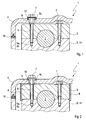
- a cylinder head 1 has a camshaft 2 mounted in a cylinder crankcase 14, which is mounted upwardly above at least one bearing upper part 3.
- the cylinder crankcase 14 is covered by a cylinder head cover 4.
- the at least one bearing upper part 3 for the camshaft 2 has at least one through-opening 5, which on the one hand has a screw-in / through-hole 5a in a bearing base 6 (cf. Fig. 6 ) and / or a screw-5b in the cylinder crankcase 14 and on the other hand with a through hole 5c in the cylinder head cover 4 is aligned.
- a fastening of the cylinder head cover 4 and the bearing upper part 3 on the cylinder crankcase 14 via a common fastening screw 7 is possible.
- the bearing upper part 3 can additionally be fastened with a fastening screw 7 'on the cylinder crankcase 14 or on a bearing base 6, which does not serve for the simultaneous fastening of the cylinder head cover 4.
- the bearing upper part 3 is made of a material having different material properties, as the cylinder cap 4th
- the at least one bearing upper part 3 is formed as a separate component from the cylinder head cover 4, wherein on the cylinder head cover 4 locking elements, in particular locking bracket 8, are arranged, which allow latching of the at least one bearing shell 3 on the cylinder head cover 4.
- locking elements in particular locking bracket 8
- the bearing shell 3 is first bolted by the screw 7 'to the bearing base 6 and the cylinder crankcase 14 and then the cylinder head cover 4 is latched by the locking bracket 8 with the bearing shell 3, so that subsequently the fastening screw 7 through the cylinder head cover 4, the Bearing upper part 3 can be screwed into the bearing base 6 and in the cylinder crankcase 14.
- the fastening screw 7 is formed as a collar screw and may have a provided between the cylinder head cover 4 and the bearing shell 3 collar 9.
- the cylinder head cover 4 is sealed relative to the cylinder crankcase 14 via a seal 10 extending along a flange and a seal 10 'arranged between the screw head and the cylinder head cover 4.
- the at least one bearing upper part 3 has at least one sleeve extension 11 aligned with the passage opening 5c in the cylinder head cover 4, which engages in the passage opening 5c of the cylinder head cover 4 when the cylinder head cover 4 is mounted and forms a stop for a screw head of the fastening screw 7.
- two fastening screws 7 may be provided, which cross both the cylinder head cover 4 and the upper bearing part 3.
- the locking bracket 8 according to the Figures 2 and 3 can be molded onto the cylinder head cover 4.
- Fig. 4 an embodiment of the cylinder head 1 according to the invention is shown, in which the bearing upper part 3 is formed as a bearing frame. In this case, a seal 10 "between the bearing upper part 3 and the cylinder crankcase 14 is provided.
- the bearing upper part 3 formed integrally with the cylinder head cover 4, wherein it can be provided that the cylinder head cover 4 is formed of a thermoplastic material and the bearing shell 3 made of a thermosetting plastic.
- the specific advantages of the individual types of plastic have already been mentioned in the introduction to the description. It is conceivable in this case that the upper bearing part 3 is molded onto the cylinder head cover 4 and, optionally, an additional bearing shell 12, in particular of aluminum, can be provided in the bearing upper part 3.
- the bearing base 6 made of plastic, in particular thermosetting plastic formed, wherein the bearing base 6 and the bearing shell 3 may be formed either as separate components or in one piece.
- the camshaft 2 is completely encapsulated.
- the composite of the two bearing parts 3 and 6 bearing can either turn separately to the cylinder head cover 4 or integrally molded, in particular molded onto this.
- the bearing base 6 has an oil supply passage 13 for supplying the camshaft bearing with lubricant.
- the cylinder head cover 4 and the associated bearing upper part 3 and / or the lower bearing part 6 is constructed as a hybrid component of at least two different materials.
- bearing shown which consists of the contiguous bearing base 6 and the associated bearing upper part 3, offers the great advantage of completely overmolding the camshaft 2 and to dispense with the machining of a camshaft bearing entirely.
Landscapes
- Engineering & Computer Science (AREA)
- Mechanical Engineering (AREA)
- General Engineering & Computer Science (AREA)
- Chemical & Material Sciences (AREA)
- Combustion & Propulsion (AREA)
- Cylinder Crankcases Of Internal Combustion Engines (AREA)
Claims (8)
- Carter-moteur (14) comportant un couvercle de culasse (4) pour recouvrir ce dernier, dans lequel au moins une partie supérieure de palier (3) pour un arbre à cames (2) présente au moins une ouverture traversante (5), qui s'aligne d'un côté avec une ouverture traversante/ de vissage (5a) dans une partie inférieure de palier (6) et/ou une ouverture de vissage (5b) dans le carter-moteur (14) et d'un autre côté avec une ouverture traversante (5c) dans le couvercle de culasse (4), de telle sorte qu'une fixation du couvercle de culasse (4) et de la partie supérieure de palier (3) sur le carter-moteur (14) soit possible par l'intermédiaire d'une vis de fixation commune (7),
caractérisé en ce que- le couvercle de culasse (4) est fabriqué dans un matériau, qui présente d'autres propriétés de matériau que la au moins une partie supérieure de palier (3),- des éléments d'encliquetage (8) sont disposés sur le couvercle de culasse (4), lesquels permettent un encliquetage d'au moins une partie supérieure de palier (3) sur le couvercle de culasse (4). - Carter-moteur selon la revendication 1,
caractérisé en ce que
la au moins une partie supérieure de palier (3) est conçue comme un composant séparé du couvercle de culasse (4). - Carter-moteur selon les revendications 1 ou 2,
caractérisé en ce que
la au moins une partie supérieure de palier (3) présente au moins un prolongement de gaine (11) s'alignant avec l'ouverture traversante (5c) dans le couvercle de culasse (4), qui lorsque le couvercle de culasse (4) est monté vient en prise avec l'ouverture traversante (5c) du couvercle de culasse (4) et forme une butée pour une tête de vis de la vis de fixation (7). - Carter-moteur selon une des revendications 1 à 3,
caractérisé en ce que
la au moins une partie supérieure de palier (3) est conçue comme un cadre de palier. - Carter-moteur selon une des revendications 1 à 4,
caractérisé en ce que
le couvercle de culasse (4) est conçu dans un plastique thermoplastique et la partie supérieure de palier (3) est conçue dans un plastique thermodurcissable. - Carter-moteur selon une des revendications 1 à 5,
caractérisé en ce que
une partie inférieure de palier (6) est conçue dans un plastique thermodurcissable, dans lequel la partie inférieure de palier et la partie supérieure de palier (6, 3) peuvent être conçues comme des composants séparés ou en un seul tenant. - Carter-moteur selon une des revendications 1 à 6,
caractérisé en ce que
dans la partie inférieure de palier (6) un canal d'huile (13) est prévu, notamment est moulé par injection. - Moteur à combustion interne comportant un carter-moteur (14) selon une des revendications 1 à 7.
Applications Claiming Priority (1)
| Application Number | Priority Date | Filing Date | Title |
|---|---|---|---|
| DE102007025129A DE102007025129A1 (de) | 2007-05-30 | 2007-05-30 | Zylinderkopfhaube |
Publications (3)
| Publication Number | Publication Date |
|---|---|
| EP1998034A2 EP1998034A2 (fr) | 2008-12-03 |
| EP1998034A3 EP1998034A3 (fr) | 2009-11-04 |
| EP1998034B1 true EP1998034B1 (fr) | 2014-02-12 |
Family
ID=39735351
Family Applications (1)
| Application Number | Title | Priority Date | Filing Date |
|---|---|---|---|
| EP08156342.1A Ceased EP1998034B1 (fr) | 2007-05-30 | 2008-05-16 | Coiffe de tête de cylindre |
Country Status (4)
| Country | Link |
|---|---|
| US (1) | US7845322B2 (fr) |
| EP (1) | EP1998034B1 (fr) |
| JP (1) | JP5124343B2 (fr) |
| DE (1) | DE102007025129A1 (fr) |
Families Citing this family (25)
| Publication number | Priority date | Publication date | Assignee | Title |
|---|---|---|---|---|
| DE102007063254A1 (de) * | 2007-12-31 | 2009-07-02 | Mahle International Gmbh | Zylinderkopfhaube |
| DE102007063257A1 (de) * | 2007-12-31 | 2009-07-02 | Mahle International Gmbh | Lagereinrichtung |
| DE102008007091B4 (de) | 2008-01-31 | 2010-06-24 | Polytec Automotive Gmbh & Co. Kg | Nockenwellenmodul |
| JP4801720B2 (ja) | 2008-12-09 | 2011-10-26 | トヨタ紡織株式会社 | 複合部材の固定構造 |
| US20120199096A1 (en) * | 2009-10-13 | 2012-08-09 | Honda Motor Co., Ltd. | Cover member fastening method and fastening structure for a head cover |
| DE102011079166A1 (de) * | 2011-07-14 | 2013-01-17 | Mahle International Gmbh | Brennkraftmaschine |
| DE102012007334A1 (de) * | 2012-04-12 | 2013-10-17 | Neumayer Tekfor Holding Gmbh | Verfahren zum Herstellen eines Nockenwellenmoduls und entsprechendes Nockenwellenmodul |
| CN103925102B (zh) * | 2014-05-07 | 2015-04-01 | 广西玉柴机器股份有限公司 | 复合式气缸盖 |
| DE102014106925B4 (de) * | 2014-05-16 | 2017-05-11 | Thyssenkrupp Presta Teccenter Ag | Lagerbrücke zur Lagerung einer Nockenwelle |
| DE102014109075A1 (de) | 2014-06-27 | 2015-12-31 | Elringklinger Ag | Zylinderkopfhaube und Verfahren zur Herstellung einer Zylinderkopfhaube |
| DE102014212446A1 (de) | 2014-06-27 | 2015-12-31 | Polytec Plastics Germany Gmbh & Co. Kg | Zylinderkopfhaube eines Kraftfahrzeuges |
| JP2018031260A (ja) * | 2015-01-08 | 2018-03-01 | 三菱自動車工業株式会社 | シリンダヘッド |
| US9725051B2 (en) * | 2015-05-01 | 2017-08-08 | Ford Global Technologies, Llc | Engine cover assembly feature |
| DE102015211068B4 (de) * | 2015-06-17 | 2021-09-16 | Thyssenkrupp Ag | Kombinationsmodul aufweisend einen Einlegering und ein Befestigungselement |
| DE102015224440A1 (de) * | 2015-12-07 | 2017-06-08 | Mahle International Gmbh | Zylinderkopfhaube |
| JP6637357B2 (ja) * | 2016-03-28 | 2020-01-29 | 本田技研工業株式会社 | パワーユニット |
| DE102016115237C5 (de) | 2016-08-17 | 2023-11-16 | Thyssenkrupp Ag | Nockenwellenmodul, Dichtung und Verfahren zur Herstellung eines Nockenwellenmoduls |
| DE102016121480B4 (de) * | 2016-11-09 | 2023-07-27 | Iav Gmbh Ingenieurgesellschaft Auto Und Verkehr | Verfahren zur Herstellung eines Nockenwellenmoduls |
| DE102017213684A1 (de) * | 2017-08-07 | 2019-02-07 | Mahle International Gmbh | Modul aus einer Zylinderkopfhaube und einem Nockenwellenlager, Verbund des Moduls mit einem Zylinderkopf sowie Verfahren zum Herstellen dieses Verbunds |
| DE102017118862A1 (de) | 2017-08-18 | 2019-02-21 | Man Truck & Bus Ag | Vorrichtung zum drehbaren Lagern einer Nockenwelle |
| DE102018205982A1 (de) * | 2018-04-19 | 2019-10-24 | Mahle International Gmbh | Lagerrahmen oder Zylinderkopfhaube einer Brennkraftmaschine |
| FR3090748B1 (fr) * | 2018-12-20 | 2020-12-25 | Renault Sas | Culasse comprenant un moyen de positionnement pour un demi-palier inférieur |
| EP4081702A4 (fr) * | 2019-12-24 | 2024-02-28 | Fleetguard Filters Private Limited | Calotte de cylindre pour moteur à combustion interne |
| DE102021201823A1 (de) * | 2021-02-26 | 2022-09-01 | Mahle International Gmbh | Zylinderkopfhaube |
| DE102022203445A1 (de) * | 2022-04-06 | 2023-10-12 | Mahle International Gmbh | Zylinderkopfhaubenanordnung |
Family Cites Families (25)
| Publication number | Priority date | Publication date | Assignee | Title |
|---|---|---|---|---|
| US1631410A (en) * | 1925-03-25 | 1927-06-07 | Fornaca Guido | Valve mechanism for internal-combustion engines |
| JPS6058994U (ja) * | 1983-09-29 | 1985-04-24 | 日産ディーゼル工業株式会社 | ロツカカバ−の取付装置 |
| DE3603938A1 (de) * | 1986-02-07 | 1987-08-13 | Bayerische Motoren Werke Ag | Vom zylinderkopf einer brennkraftmaschine gesondert ausgebildetes steuergehaeuse |
| JPS6394059A (ja) * | 1986-10-09 | 1988-04-25 | Yamaha Motor Co Ltd | 自動二輪車等の車両用4サイクルエンジン |
| US5070824A (en) * | 1988-05-30 | 1991-12-10 | Yamaha Hatsudoki Kabushiki Kaisha | Combustion chamber and valve operating mechanism for multi-valve engine |
| JP2794900B2 (ja) * | 1990-05-23 | 1998-09-10 | 松下電器産業株式会社 | ピンチローラ装置 |
| DE4017048C2 (de) | 1990-05-26 | 1994-05-05 | Opel Adam Ag | Zylinderkopf |
| DE4323073A1 (de) | 1993-07-10 | 1995-01-12 | Audi Ag | Hubkolben-Brennkraftmaschine |
| DE4324791A1 (de) * | 1993-07-23 | 1995-01-26 | Porsche Ag | Zylinderkopfanordnung einer Brennkraftmaschine |
| DE19603692A1 (de) * | 1996-02-02 | 1997-08-07 | Mbi Maschinen Und Bauingenieur | Zylinderkopfdeckel mit integrierter Nockenwellen-Lagergasse für Kolbenverbrennungsmotoren |
| US5987973A (en) * | 1996-07-24 | 1999-11-23 | Honda Giken Kogyo Kabushiki Kaisha | Rotation detecting device of an engine |
| JPH11324846A (ja) * | 1998-05-11 | 1999-11-26 | Yamaha Motor Co Ltd | 内燃機関 |
| JP2000027665A (ja) * | 1998-07-14 | 2000-01-25 | Ge Plastics Japan Ltd | 樹脂製スロットルチャンバおよびその製造方法 |
| JP2000045742A (ja) * | 1998-07-29 | 2000-02-15 | Honda Motor Co Ltd | 潤滑油吐出口 |
| US6257188B1 (en) * | 1998-09-02 | 2001-07-10 | Honda Giken Kogyo Kabushiki Kaisha | Structure for mounting cylinder head cover of internal combustion engine |
| DE19853537A1 (de) | 1998-11-20 | 2000-05-25 | Audi Ag | Brennkraftmaschine |
| US6796281B2 (en) | 2001-11-19 | 2004-09-28 | Honda Giken Kogyo Kabushiki Kaisha | Internal combustion engine with valve train |
| ITPR20010080A1 (it) | 2001-11-19 | 2003-05-19 | Amps Spa | Procedimento per la condensazione di vapore proveniente |
| JP3714463B2 (ja) * | 2001-11-19 | 2005-11-09 | 本田技研工業株式会社 | 動弁装置を備える内燃機関 |
| DE20120912U1 (de) | 2001-12-24 | 2002-06-06 | Volkswagen Ag, 38440 Wolfsburg | Zylinderkopfhaube für eine Brennkraftmaschine |
| DE10332648A1 (de) * | 2003-07-18 | 2005-02-24 | Ab Skf | Gehäuse für ein Lager |
| DE102005028332A1 (de) | 2005-06-18 | 2007-01-04 | Daimlerchrysler Ag | Zylinderkopfhaube |
| DE102005028331A1 (de) | 2005-06-18 | 2006-12-21 | Schnell, Hans-Günther | Bugwulst-Spannungskonverter |
| DE102005030914A1 (de) * | 2005-06-30 | 2007-01-11 | Mann + Hummel Gmbh | Ventilkammerdeckel |
| DE202005013879U1 (de) * | 2005-09-01 | 2007-01-11 | Mann + Hummel Gmbh | Zylinderkopfhaube |
-
2007
- 2007-05-30 DE DE102007025129A patent/DE102007025129A1/de not_active Withdrawn
-
2008
- 2008-05-16 EP EP08156342.1A patent/EP1998034B1/fr not_active Ceased
- 2008-05-26 JP JP2008136291A patent/JP5124343B2/ja not_active Expired - Fee Related
- 2008-05-29 US US12/129,298 patent/US7845322B2/en not_active Expired - Fee Related
Also Published As
| Publication number | Publication date |
|---|---|
| EP1998034A2 (fr) | 2008-12-03 |
| US7845322B2 (en) | 2010-12-07 |
| US20080295796A1 (en) | 2008-12-04 |
| JP5124343B2 (ja) | 2013-01-23 |
| DE102007025129A1 (de) | 2008-12-04 |
| JP2008298072A (ja) | 2008-12-11 |
| EP1998034A3 (fr) | 2009-11-04 |
Similar Documents
| Publication | Publication Date | Title |
|---|---|---|
| EP1998034B1 (fr) | Coiffe de tête de cylindre | |
| DE2520612A1 (de) | Abflusstoepselanordnung | |
| DE102012024653B4 (de) | Entkopplungselement | |
| DE102007041949B3 (de) | Befestiger | |
| DE102008015579A1 (de) | Anschlaganordnung und Verfahren zum Einrichten eines Anschlages für zwei gegeneinander bewegliche Bauteile | |
| DE102007046531B3 (de) | Abdichtvorrichtung zur Abdichtung zwischen einem Lenkgetriebegehäuse und einem Stirnwandblech einer Kraftfahrzeugkarosserie | |
| DE102006004678A1 (de) | Montageeinheit für die Befestigungsöse eines Gurtschlosses | |
| DE102007063255A1 (de) | Lagereinrichtung | |
| WO2013056780A1 (fr) | Procédé de fabrication d'un entraînement à vis sans fin pour un élément de réglage d'un véhicule automobile | |
| DE102011010037A1 (de) | Vorrichtung zur Befestigung eines ersten Bauteils an einem zweiten Bauteil | |
| EP2177725B2 (fr) | Dispositif de filtre | |
| EP3037150B1 (fr) | Dispositif de filtre | |
| EP3179060A1 (fr) | Capot de culasse | |
| EP2331805B1 (fr) | Dispositif de filtration pour moteurs à combustion interne | |
| DE102008020099B4 (de) | Durch mindestens eine Befestigungsschraube zu montierendes Bauteil | |
| DE102006022382A1 (de) | Vorrichtung und Verfahren zur Befestigung eines Wischermotors an ein Wischergestänge | |
| DE102009020658A1 (de) | Kopplungsvorrichtung, insbesondere für eine Fahrzeuglenkspindel | |
| DE10360291A1 (de) | Wankstabilisator | |
| DE102005062546A1 (de) | Zylinderkopfhaube in Verbundbauweise | |
| EP3122435B1 (fr) | Support de filtre en polymere avec manchon metallique | |
| DE102008023635B4 (de) | Tülle | |
| DE9405633U1 (de) | Dichtelement für die Durchführung der Lenksäule durch die Spritzwand eines Kraftfahrzeuges | |
| DE102008016390B4 (de) | Filtereinrichtung | |
| EP2233189B1 (fr) | Vis creuse | |
| DE102009021358A1 (de) | Stirnwandteil |
Legal Events
| Date | Code | Title | Description |
|---|---|---|---|
| PUAI | Public reference made under article 153(3) epc to a published international application that has entered the european phase |
Free format text: ORIGINAL CODE: 0009012 |
|
| AK | Designated contracting states |
Kind code of ref document: A2 Designated state(s): AT BE BG CH CY CZ DE DK EE ES FI FR GB GR HR HU IE IS IT LI LT LU LV MC MT NL NO PL PT RO SE SI SK TR |
|
| AX | Request for extension of the european patent |
Extension state: AL BA MK RS |
|
| PUAL | Search report despatched |
Free format text: ORIGINAL CODE: 0009013 |
|
| AK | Designated contracting states |
Kind code of ref document: A3 Designated state(s): AT BE BG CH CY CZ DE DK EE ES FI FR GB GR HR HU IE IS IT LI LT LU LV MC MT NL NO PL PT RO SE SI SK TR |
|
| AX | Request for extension of the european patent |
Extension state: AL BA MK RS |
|
| 17P | Request for examination filed |
Effective date: 20091216 |
|
| 17Q | First examination report despatched |
Effective date: 20100202 |
|
| AKX | Designation fees paid |
Designated state(s): DE FR GB |
|
| GRAP | Despatch of communication of intention to grant a patent |
Free format text: ORIGINAL CODE: EPIDOSNIGR1 |
|
| INTG | Intention to grant announced |
Effective date: 20130917 |
|
| GRAS | Grant fee paid |
Free format text: ORIGINAL CODE: EPIDOSNIGR3 |
|
| GRAA | (expected) grant |
Free format text: ORIGINAL CODE: 0009210 |
|
| AK | Designated contracting states |
Kind code of ref document: B1 Designated state(s): DE FR GB |
|
| REG | Reference to a national code |
Ref country code: GB Ref legal event code: FG4D Free format text: NOT ENGLISH |
|
| REG | Reference to a national code |
Ref country code: DE Ref legal event code: R096 Ref document number: 502008011305 Country of ref document: DE Effective date: 20140327 |
|
| REG | Reference to a national code |
Ref country code: DE Ref legal event code: R097 Ref document number: 502008011305 Country of ref document: DE |
|
| PLBE | No opposition filed within time limit |
Free format text: ORIGINAL CODE: 0009261 |
|
| STAA | Information on the status of an ep patent application or granted ep patent |
Free format text: STATUS: NO OPPOSITION FILED WITHIN TIME LIMIT |
|
| 26N | No opposition filed |
Effective date: 20141113 |
|
| REG | Reference to a national code |
Ref country code: DE Ref legal event code: R097 Ref document number: 502008011305 Country of ref document: DE Effective date: 20141113 |
|
| REG | Reference to a national code |
Ref country code: FR Ref legal event code: PLFP Year of fee payment: 9 |
|
| REG | Reference to a national code |
Ref country code: FR Ref legal event code: PLFP Year of fee payment: 10 |
|
| REG | Reference to a national code |
Ref country code: FR Ref legal event code: PLFP Year of fee payment: 11 |
|
| PGFP | Annual fee paid to national office [announced via postgrant information from national office to epo] |
Ref country code: FR Payment date: 20190528 Year of fee payment: 12 |
|
| PGFP | Annual fee paid to national office [announced via postgrant information from national office to epo] |
Ref country code: DE Payment date: 20190731 Year of fee payment: 12 Ref country code: GB Payment date: 20190529 Year of fee payment: 12 |
|
| REG | Reference to a national code |
Ref country code: DE Ref legal event code: R119 Ref document number: 502008011305 Country of ref document: DE |
|
| GBPC | Gb: european patent ceased through non-payment of renewal fee |
Effective date: 20200516 |
|
| PG25 | Lapsed in a contracting state [announced via postgrant information from national office to epo] |
Ref country code: GB Free format text: LAPSE BECAUSE OF NON-PAYMENT OF DUE FEES Effective date: 20200516 Ref country code: FR Free format text: LAPSE BECAUSE OF NON-PAYMENT OF DUE FEES Effective date: 20200531 |
|
| PG25 | Lapsed in a contracting state [announced via postgrant information from national office to epo] |
Ref country code: DE Free format text: LAPSE BECAUSE OF NON-PAYMENT OF DUE FEES Effective date: 20201201 |