EP1998051A2 - Système de ventilateur - Google Patents
Système de ventilateur Download PDFInfo
- Publication number
- EP1998051A2 EP1998051A2 EP08104158A EP08104158A EP1998051A2 EP 1998051 A2 EP1998051 A2 EP 1998051A2 EP 08104158 A EP08104158 A EP 08104158A EP 08104158 A EP08104158 A EP 08104158A EP 1998051 A2 EP1998051 A2 EP 1998051A2
- Authority
- EP
- European Patent Office
- Prior art keywords
- fan
- fan system
- fan blades
- metres
- blades
- Prior art date
- Legal status (The legal status is an assumption and is not a legal conclusion. Google has not performed a legal analysis and makes no representation as to the accuracy of the status listed.)
- Withdrawn
Links
Images
Classifications
-
- F—MECHANICAL ENGINEERING; LIGHTING; HEATING; WEAPONS; BLASTING
- F04—POSITIVE - DISPLACEMENT MACHINES FOR LIQUIDS; PUMPS FOR LIQUIDS OR ELASTIC FLUIDS
- F04D—NON-POSITIVE-DISPLACEMENT PUMPS
- F04D29/00—Details, component parts, or accessories
- F04D29/26—Rotors specially for elastic fluids
- F04D29/32—Rotors specially for elastic fluids for axial flow pumps
- F04D29/38—Blades
- F04D29/384—Blades characterised by form
-
- F—MECHANICAL ENGINEERING; LIGHTING; HEATING; WEAPONS; BLASTING
- F04—POSITIVE - DISPLACEMENT MACHINES FOR LIQUIDS; PUMPS FOR LIQUIDS OR ELASTIC FLUIDS
- F04D—NON-POSITIVE-DISPLACEMENT PUMPS
- F04D25/00—Pumping installations or systems
- F04D25/02—Units comprising pumps and their driving means
- F04D25/08—Units comprising pumps and their driving means the working fluid being air, e.g. for ventilation
- F04D25/088—Ceiling fans
Definitions
- the invention relates to a fan system, comprising a frame for mounting of the fan system, for instance on a ceiling of a building, a motor mounted on the frame, a rotatable shaft coupled to the motor, and a number of fan blades which are attached at an angle of tilt to the rotatable shaft.
- the known fan system is intended for the purpose of cooling an industrial building and comprises ten fan blades which are attached to the rotatable shaft at an ⁇ angle of attac eight degrees to the plane of rotation.
- Described in EP 1173359 are measurement results which show that at a rotation speed of 50 rotations per minute the fan blades produce a column of moving air which is about 6 to 7.3 metres in diameter at a position in the immediate vicinity of the fan blades, wherein air has a speed of about 1.3 to 2.2 metres per second at a distance of about 3 metres from the blade.
- a moving volume of air is thus entrained in advantageous manner in a flow in a circulating pattern through the industrial building to thereby disrupt the boundary layer of air close to the individuals present so as to facilitate evaporation of sweat from the individual.
- the present invention has for its object to provide an improved embodiment of the known fan system.
- the fan system according to the invention has for this purpose the feature that the angle of tilt amounts to between substantially 15 and 25 degrees, preferably substantially 20 degrees.
- the fan blades at a rotation speed of the fan blades of approximately 51 rotations per minute, produce a column of moving air such that air has a speed of approximately 34 metres per second at a distance of approximately three metres from the outer end of a fan blade.
- the ratio of the air speed measured in metres per second to the rotation speed of the fan blades in rotations per minute has a value ⁇ 1, irrespective of the distance to the tip.
- a rotor element provided with a number of radially extending rotor arms for attaching of the fan blades.
- the fan blades take an at least partially hollow form for the purpose of receiving the rotor arms.
- each rotor arm is chamfered on one side at two diagonally opposite corners. After assembly each fan blade automatically lies at the desired angle of tilt.
- the length of the fan blades amounts to a maximum of two metres.
- each fan blade has a propeller blade section.
- the optimum number of fan blades amounts to six.
- the motor is provided with a control adapted to cause rotation of the shaft both to the left and the right.
- the generated airflow can run upward from below, or vice versa, as a result which respectively cooling or heating occurs.
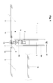
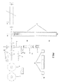
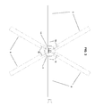
- Figures 1 and 2 show a preferred embodiment of a fan system 1 according to the invention.
- Fan system 1 comprises a frame 2 in which a motor 3 is accommodated.
- Motor 3 drives a rotatable shaft 4 to which a number of fan blades 5 are attached.
- frame 2 of fan system 1 is provided with means 22 for mounting on a ceiling of a building.
- Frame 2 further comprises two parts 2A and 2B which engage slidably in each other in lengthwise direction.
- the distance of fan blades 5 from the means 22 for mounting on the ceiling is hereby adjustable in continuously variable manner.
- motor 3 which is coupled to rotatable shaft 4 by means of a transmission 13.
- Motor 3 is supported by a fixing plate 11.
- Two bearings 16 and locking rings 12 are arranged on the shaft.
- Fan system 1 further comprises a rotor element 10 arranged on rotatable shaft 4.
- Rotor element 10 comprises two discs 6, 7 with a central opening 14 for passage of shaft 4. Situated between the two discs 6, 7 are a number of radially extending rotor arms 15 for attachment of fan blades 5.
- Fan blades 5 take a hollow form at an outer end for the purpose of receiving rotor arms 15. Fan blades 5 lie at an angle of tilt , also referred to as ⁇ angle of attack ⁇ , relati own plane of rotation R. Angle of tilt amounts substantially to between 15 and 25 degrees, preferably substantially 20 degrees.
- Rotor arms 15 are preformed such that fan blades 5 are automatically in the desired oblique position after mounting, i.e. at the predetermined angle of tilt.
- each rotor arm 15 is chamfered over the angle of tilt on one side at two opposite corners. This is shown in the inset in figure 2 .
- the length of fan blades 5 amounts to a maximum of two metres.
- Each fan blade has a propeller blade section.
- the number of fan blades can vary and preferably amounts to six.
- the components of the fan system can be manufactured from diverse materials.
- the rotor arms and the fan blades are preferably of aluminium.
- An example of a suitable motor has the following specifications: 0.55 kW, 220/380 V, 1480 revolutions.
- the motor is preferably provided with a control adapted to cause rotation of the shaft both to the left and the right.
- An example of a suitable motor is provided with a double motor protection connected in parallel, wherein the choice of the motor protection determines the rotation direction.
- An example of a suitable motor is provided with a speed regulation. This can be hand-operated as well as automatic, for instance temperature-controlled. Such motors are commercially available.
- An example of a suitable transmission has the following specifications: 535/1480 - 2158 revolutions (20/50 Hz). Such a transmission is commercially available.
- Table 1 shows measurement results from a prototype of a fan system according to the invention.
- the measurement results show the air speed (AS) in metres per second at different values of the rotation speed (RS) of the fan blades given in rotations per minute (T).
- the air speed is measured at different distances (respectively 1, 2, 3, 4 and 5 metres) from the outer end of each of the fan blades at one meter from the plane of rotation of the fan blades in the direction of the air movement.
- table 2 shows the measured values for the air speed in metres per second below the centre of the same prototype of the fan system according to the invention at different values of the rotation speed of the fan blades given in rotations per minute (T).
- Table 2 RS AS below 21T 4 m/s 26T 10 m/s 31T 13 m/s 36T 17 m/s 41T 20 m/s 46T 27 m/s 51T 31 m/s 58T 40 m/s
- Table 1 shows that the fan blades of the fan system according to the invention, at a rotation speed of the fan blades of approximately 51 rotations per minute, produce a column of moving air such that air has a speed of approximately 34 metres per second at a distance of approximately three metres from the outer end of a fan blade.
- the air speed in the known fan assembly is between 1.3 and 2.2 metres per second at a rotation speed of 50 rotations per minute.
- the table further shows that the ratio of the air speed measured in metres per second to the rotation speed of the fan blades in rotations per minute has a value ⁇ 1. This is the case irrespective of the distance to the outer end of a fan blade.
- the present invention generally provides a technically reliable fan system which can realize a surprisingly large air displacement. At high outside temperatures this can be employed to cool large spaces by generating an airflow upward from below. At low outside temperatures this can be employed to heat large spaces by generating an airflow downward from above.
- the fan system according to the invention is moreover simple to assemble. The components can also be produced at low cost. The fan system can be produced in diverse embodiments.
Landscapes
- Engineering & Computer Science (AREA)
- Mechanical Engineering (AREA)
- General Engineering & Computer Science (AREA)
- Structures Of Non-Positive Displacement Pumps (AREA)
Applications Claiming Priority (1)
| Application Number | Priority Date | Filing Date | Title |
|---|---|---|---|
| NL2000667A NL2000667C2 (nl) | 2007-05-29 | 2007-05-29 | Ventilatorsysteem. |
Publications (2)
| Publication Number | Publication Date |
|---|---|
| EP1998051A2 true EP1998051A2 (fr) | 2008-12-03 |
| EP1998051A3 EP1998051A3 (fr) | 2011-07-27 |
Family
ID=38951886
Family Applications (1)
| Application Number | Title | Priority Date | Filing Date |
|---|---|---|---|
| EP08104158A Withdrawn EP1998051A3 (fr) | 2007-05-29 | 2008-05-29 | Système de ventilateur |
Country Status (2)
| Country | Link |
|---|---|
| EP (1) | EP1998051A3 (fr) |
| NL (1) | NL2000667C2 (fr) |
Citations (5)
| Publication number | Priority date | Publication date | Assignee | Title |
|---|---|---|---|---|
| GB509013A (en) * | 1938-01-06 | 1939-07-06 | Gen Electric Co Ltd | Improvements in or relating to blades for screw fans |
| EP1173359A2 (fr) | 1999-02-19 | 2002-01-23 | Mechanization Systems Company, Inc. | Ventilateur de refroidissement tournant petite vitesse |
| US20040131470A1 (en) * | 2003-01-06 | 2004-07-08 | Walter Boyd | Cooling fan with reinforced blade |
| US20060018758A1 (en) * | 2004-07-21 | 2006-01-26 | Aynsley Richard M | Fan blades |
| GB2427000A (en) * | 2005-06-08 | 2006-12-13 | Jacob Dyson | Dual rotor fan |
Family Cites Families (5)
| Publication number | Priority date | Publication date | Assignee | Title |
|---|---|---|---|---|
| US2032616A (en) * | 1935-08-16 | 1936-03-03 | Horsky Milvoy | Fan |
| JPS5688995U (fr) * | 1979-12-12 | 1981-07-16 | ||
| US7210910B1 (en) * | 1998-04-07 | 2007-05-01 | Research Foundation Of The University Of Central Florida, Inc. | Enhancements to high efficiency ceiling fan |
| US20040042903A1 (en) * | 2002-08-27 | 2004-03-04 | Mao-Lin Huang | Combination structure of the blade rack and the blade of a ceiling fan |
| US20050249598A1 (en) * | 2004-05-05 | 2005-11-10 | Stanfield Young | Ceiling fan with multiple motors |
-
2007
- 2007-05-29 NL NL2000667A patent/NL2000667C2/nl not_active IP Right Cessation
-
2008
- 2008-05-29 EP EP08104158A patent/EP1998051A3/fr not_active Withdrawn
Patent Citations (5)
| Publication number | Priority date | Publication date | Assignee | Title |
|---|---|---|---|---|
| GB509013A (en) * | 1938-01-06 | 1939-07-06 | Gen Electric Co Ltd | Improvements in or relating to blades for screw fans |
| EP1173359A2 (fr) | 1999-02-19 | 2002-01-23 | Mechanization Systems Company, Inc. | Ventilateur de refroidissement tournant petite vitesse |
| US20040131470A1 (en) * | 2003-01-06 | 2004-07-08 | Walter Boyd | Cooling fan with reinforced blade |
| US20060018758A1 (en) * | 2004-07-21 | 2006-01-26 | Aynsley Richard M | Fan blades |
| GB2427000A (en) * | 2005-06-08 | 2006-12-13 | Jacob Dyson | Dual rotor fan |
Also Published As
| Publication number | Publication date |
|---|---|
| NL2000667C2 (nl) | 2008-12-02 |
| EP1998051A3 (fr) | 2011-07-27 |
Similar Documents
| Publication | Publication Date | Title |
|---|---|---|
| US11022127B2 (en) | Laminar flow radial ceiling fan | |
| US6379116B1 (en) | Impeller and structure for an impeller housing | |
| US6817835B2 (en) | Low speed cooling fan | |
| EP2504580B1 (fr) | Ventilateur de plafond centrifuge | |
| US9546665B2 (en) | Levitating ceiling fan | |
| EP2846045A1 (fr) | Ventilateur | |
| US10527046B2 (en) | Stepped-louvre heating, ventilating and air conditioning unit used in high volume, low-speed fan | |
| US20120328430A1 (en) | Spiral tower fan | |
| US5333235A (en) | Electric heater assembly for attachment to ceiling fans | |
| KR20210002685A (ko) | 선풍기 | |
| WO2004109190A3 (fr) | Climatiseur | |
| US11603856B2 (en) | Backward curved plenum fan having enhanced efficiency | |
| US10774840B2 (en) | Fan blades, fans, and a method of cooling a room | |
| US20170356664A1 (en) | Hvac delivery system in high volume low-speed fan | |
| CN213094756U (zh) | 风道散热装置 | |
| EP4018096B1 (fr) | Ventilateur pour unité de traitement d'air (ahu) assemblé à partir de plusieurs parties avec des éléments de retenue radiaux et axiaux | |
| WO2018042381A1 (fr) | Ventilateur de plafond | |
| NL2000667C2 (nl) | Ventilatorsysteem. | |
| JP2006042543A (ja) | 誘導電動機 | |
| KR100883207B1 (ko) | 원형 천정형 에어컨 및 이를 이용한 집중냉방시스템 | |
| CN220287593U (zh) | 空调器 | |
| JP2019074029A (ja) | シーリングファン | |
| KR200485674Y1 (ko) | 선풍기 | |
| CN113472145A (zh) | 机器人应用大功率电机散热保护装置 | |
| GB2515329A (en) | An axial fan for bi-directional air movement |
Legal Events
| Date | Code | Title | Description |
|---|---|---|---|
| PUAI | Public reference made under article 153(3) epc to a published international application that has entered the european phase |
Free format text: ORIGINAL CODE: 0009012 |
|
| AK | Designated contracting states |
Kind code of ref document: A2 Designated state(s): AT BE BG CH CY CZ DE DK EE ES FI FR GB GR HR HU IE IS IT LI LT LU LV MC MT NL NO PL PT RO SE SI SK TR |
|
| AX | Request for extension of the european patent |
Extension state: AL BA MK RS |
|
| PUAL | Search report despatched |
Free format text: ORIGINAL CODE: 0009013 |
|
| AK | Designated contracting states |
Kind code of ref document: A3 Designated state(s): AT BE BG CH CY CZ DE DK EE ES FI FR GB GR HR HU IE IS IT LI LT LU LV MC MT NL NO PL PT RO SE SI SK TR |
|
| AX | Request for extension of the european patent |
Extension state: AL BA MK RS |
|
| 17P | Request for examination filed |
Effective date: 20120127 |
|
| AKX | Designation fees paid |
Designated state(s): AT BE BG CH CY CZ DE DK EE ES FI FR GB GR HR HU IE IS IT LI LT LU LV MC MT NL NO PL PT RO SE SI SK TR |
|
| STAA | Information on the status of an ep patent application or granted ep patent |
Free format text: STATUS: EXAMINATION IS IN PROGRESS |
|
| 17Q | First examination report despatched |
Effective date: 20170419 |
|
| STAA | Information on the status of an ep patent application or granted ep patent |
Free format text: STATUS: THE APPLICATION IS DEEMED TO BE WITHDRAWN |
|
| 18D | Application deemed to be withdrawn |
Effective date: 20190710 |