EP1998070A2 - Amortisseur de vibrations, en particulier amortisseurs de direction - Google Patents
Amortisseur de vibrations, en particulier amortisseurs de direction Download PDFInfo
- Publication number
- EP1998070A2 EP1998070A2 EP08153747A EP08153747A EP1998070A2 EP 1998070 A2 EP1998070 A2 EP 1998070A2 EP 08153747 A EP08153747 A EP 08153747A EP 08153747 A EP08153747 A EP 08153747A EP 1998070 A2 EP1998070 A2 EP 1998070A2
- Authority
- EP
- European Patent Office
- Prior art keywords
- cylinder
- space
- housing
- vibration damper
- piston rod
- Prior art date
- Legal status (The legal status is an assumption and is not a legal conclusion. Google has not performed a legal analysis and makes no representation as to the accuracy of the status listed.)
- Withdrawn
Links
- 238000013016 damping Methods 0.000 claims description 9
- 239000007789 gas Substances 0.000 description 5
- 238000010276 construction Methods 0.000 description 3
- 230000036316 preload Effects 0.000 description 3
- IJGRMHOSHXDMSA-UHFFFAOYSA-N Atomic nitrogen Chemical compound N#N IJGRMHOSHXDMSA-UHFFFAOYSA-N 0.000 description 2
- 230000017525 heat dissipation Effects 0.000 description 2
- 238000009434 installation Methods 0.000 description 2
- 239000003795 chemical substances by application Substances 0.000 description 1
- 238000005187 foaming Methods 0.000 description 1
- 229910052757 nitrogen Inorganic materials 0.000 description 1
Images
Classifications
-
- F—MECHANICAL ENGINEERING; LIGHTING; HEATING; WEAPONS; BLASTING
- F16—ENGINEERING ELEMENTS AND UNITS; GENERAL MEASURES FOR PRODUCING AND MAINTAINING EFFECTIVE FUNCTIONING OF MACHINES OR INSTALLATIONS; THERMAL INSULATION IN GENERAL
- F16F—SPRINGS; SHOCK-ABSORBERS; MEANS FOR DAMPING VIBRATION
- F16F9/00—Springs, vibration-dampers, shock-absorbers, or similarly-constructed movement-dampers using a fluid or the equivalent as damping medium
- F16F9/06—Springs, vibration-dampers, shock-absorbers, or similarly-constructed movement-dampers using a fluid or the equivalent as damping medium using both gas and liquid
- F16F9/064—Units characterised by the location or shape of the expansion chamber
Definitions
- the invention relates to a vibration damper according to the preamble of patent claim 1.
- Steering dampers are usually designed as hydraulic vibration dampers and are very often installed horizontally.
- the volume displaced within the cylinder when the piston rod is moved in a stroke must be compensated.
- a compensation chamber is used for the different types are known. Due to the horizontal mounting position, it must be ensured that no air can penetrate into the cylinder, which could lead to foaming of the hydraulic damping medium.
- the DE 38 40 352 A1 describes a monotube vibration damper with a bottom valve between the piston rod remote working space and the compensation chamber.
- a sleeve is disposed within the cylinder, which carries the bottom valve.
- the gas-filled compensation chamber is also located within this sleeve.
- a smaller diameter is available for the compensation chamber than for the piston on the piston rod.
- it is advantageous to use the largest possible compensation space since then the ratio of piston rod volume to compensation chamber volume is small and thus the pressure increase from the extended piston rod to the retracted piston rod is also small in order to minimize an additional Ausfahrkraft.
- the US 2 410 539 describes a vibration damper according to the two-pipe construction principle. Concentric with the inner cylinder, an outer container tube is arranged, which is connected via at least one connection opening with an external expansion tank. However, this design is particularly complex because of the additional container and its connection.
- the object of the present invention is to realize a vibration damper, which is also usable in the horizontal installation position, which has a generally simple structure.
- the object is achieved in that a balancing chamber under pressure holding biasing space in a series arrangement to the two Working space is executed, wherein the biasing space is formed by a arranged in the container tube and separate from the cylinder housing.
- a significant advantage is that the vibration damper is a self-contained unit without external connections. Furthermore, the shape of the housing and thus the size of the compensation chamber is not influenced by the cylinder.
- the housing has a larger inner diameter than the cylinder.
- a larger housing allows the use of a larger separating piston between the piston rod remote working space and the biasing space. As a result, the prestressing pressure on the separating piston can be significantly reduced.
- the housing is delimited in the direction of the cylinder by the bottom valve.
- the bottom valve For positioning the housing in the container tube, the bottom valve has a centering projection for the housing.
- the housing can be mounted as a unit in the container tube, since the housing is closed at the opposite end of the bottom valve by a lid independent of the container tube.
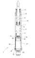
- the single FIGURE shows a vibration damper 1 with a cylinder 3, in which a piston rod 5 is guided axially movably together with a piston 7.
- the equipped with damping valves piston 7 divides the cylinder 3 in a piston rod-side working space 9 and a piston rod remote working space 11.
- a bottom valve 15 is arranged, which has an effective in the retraction of the piston rod damping valve and for the extension direction in the flow direction of the piston rod remote working chamber opening check valve.
- the entire cylinder 3 is enveloped by a concentrically arranged container tube 17, wherein between the container tube and the outer wall of the cylinder filled with a damping medium equalization chamber 19 is present.
- a housing 21 separate from the container tube is arranged in the container tube 17.
- the housing is bounded in the direction of the cylinder by the bottom valve 15.
- an axially displaceable separating piston 25 is arranged, which separates a biasing space 27 of a present between the bottom valve and the separating piston part compensating chamber 29.
- the preload space is z. Nitrogen or air, wherein the pressure level is only slightly greater than the ambient pressure of the vibration damper.
- the housing 21 is braced between a spigot 31 of the bottom valve 15 and a container tube bottom 33.
- the housing has a larger inner diameter than the cylinder.
- the pressure level in the biasing chamber 27 can be kept very small, wherein the pressure level in the preload space is partially decoupled by the interposition of the bottom valve 15 of the maximum damping force in the retraction direction.
- the large separating piston ensures a large volume in the housing so that the volume displaced by the piston rod in the retraction direction to the housing volume low.
- the container tube is designed to be so large that even between the housing 21 and the inner wall of the container tube, an annular space 35 can be used as a further part of the total volume of the compensation chamber, in particular with the advantage that the heat dissipation can take place over a particularly large area.
Landscapes
- Engineering & Computer Science (AREA)
- General Engineering & Computer Science (AREA)
- Mechanical Engineering (AREA)
- Fluid-Damping Devices (AREA)
Applications Claiming Priority (1)
| Application Number | Priority Date | Filing Date | Title |
|---|---|---|---|
| DE102007025733A DE102007025733A1 (de) | 2007-06-01 | 2007-06-01 | Schwingungsdämpfer, insbesondere Lenkungsdämpfer |
Publications (2)
| Publication Number | Publication Date |
|---|---|
| EP1998070A2 true EP1998070A2 (fr) | 2008-12-03 |
| EP1998070A3 EP1998070A3 (fr) | 2014-05-07 |
Family
ID=39720694
Family Applications (1)
| Application Number | Title | Priority Date | Filing Date |
|---|---|---|---|
| EP08153747.4A Withdrawn EP1998070A3 (fr) | 2007-06-01 | 2008-03-31 | Amortisseur de vibrations, en particulier amortisseurs de direction |
Country Status (4)
| Country | Link |
|---|---|
| EP (1) | EP1998070A3 (fr) |
| AR (1) | AR066753A1 (fr) |
| BR (1) | BRPI0801736A2 (fr) |
| DE (1) | DE102007025733A1 (fr) |
Cited By (4)
| Publication number | Priority date | Publication date | Assignee | Title |
|---|---|---|---|---|
| CN107917163A (zh) * | 2017-12-25 | 2018-04-17 | 南阳淅减汽车减振器有限公司 | 一种具有一体式补偿阀限位器的压缩阀总成 |
| WO2018103881A1 (fr) * | 2016-12-10 | 2018-06-14 | Hydac Technology Gmbh | Système cylindre-piston hydropneumatique |
| CN108180248A (zh) * | 2017-12-29 | 2018-06-19 | 南阳淅减汽车减振器有限公司 | 一种压缩阀总成 |
| CN112874629A (zh) * | 2019-11-29 | 2021-06-01 | 比亚迪股份有限公司 | 转向装置、具有该转向装置的车辆和车辆转向方法 |
Families Citing this family (3)
| Publication number | Priority date | Publication date | Assignee | Title |
|---|---|---|---|---|
| DE102015224811A1 (de) * | 2015-12-10 | 2017-06-14 | Zf Friedrichshafen Ag | Schwingungsdämpfer für ein Kraftfahrzeug |
| DE202016100438U1 (de) | 2016-01-29 | 2016-02-16 | Thyssenkrupp Ag | Schwingungsdämpfer |
| DE202016004091U1 (de) | 2016-07-01 | 2016-08-21 | Thyssenkrupp Ag | Schwingungsdämpfer |
Citations (5)
| Publication number | Priority date | Publication date | Assignee | Title |
|---|---|---|---|---|
| US2410539A (en) | 1944-08-28 | 1946-11-05 | Monroe Auto Equipment Co | Shock absorber structure |
| DE1205778B (de) | 1963-03-14 | 1965-11-25 | Boge Gmbh | Zweirohrteleskopdaempfer fuer horizontalen Einbau bei Kraftfahrzeugen |
| DE2906356A1 (de) | 1979-02-19 | 1980-08-21 | Boge Gmbh | Hydraulischer zweirohrschwingungsdaempfer mit daempfungsgemindertem hubbereich, insbesondere fuer schienenfahrzeuge |
| DE3516751A1 (de) | 1984-05-11 | 1985-11-14 | Société MTE, Puteaux | Elastischer ausgleichsbehaelter fuer hydraulische leistungsverbraucher |
| DE3840352A1 (de) | 1988-11-30 | 1990-06-21 | Irmscher Gmbh | Einrohr-gasdruck-stossdaempfer |
Family Cites Families (12)
| Publication number | Priority date | Publication date | Assignee | Title |
|---|---|---|---|---|
| AT175483B (de) | 1949-11-29 | 1953-07-10 | Procedo G M B H | Teleskopstoßdämpfer |
| DE1157857B (de) * | 1961-02-10 | 1963-11-21 | Boge Gmbh | Teleskopschwingungsdaempfer, insbesondere fuer Kraftfahrzeuge |
| GB957453A (en) * | 1961-09-21 | 1964-05-06 | Girling Ltd | Diaphragm for fluid pressure apparatus |
| GB2076933B (en) * | 1980-06-03 | 1984-08-22 | Lucas Industries Ltd | Hydropneumatic suspension struts for vehicles |
| AT378689B (de) * | 1983-05-13 | 1985-09-10 | Naepflin Hans | Sicherheitsbindung |
| FR2554195A1 (fr) * | 1983-11-02 | 1985-05-03 | Vanhoutte Daniele | Dispositif de verin hydraulique, notamment pour appareil de musculation |
| DE3644447A1 (de) * | 1986-12-24 | 1988-07-07 | Bosch Gmbh Robert | Vorrichtung zur daempfung von bewegungsablaeufen |
| DE19755039C2 (de) * | 1997-12-11 | 1999-10-21 | Mannesmann Sachs Ag | Federbein mit außenliegendem Speicher |
| DE10019531C2 (de) * | 2000-04-20 | 2003-08-07 | Zf Sachs Ag | Federungssystem für Kraftfahrzeuge |
| DE10019532C2 (de) * | 2000-04-20 | 2002-06-27 | Zf Sachs Ag | Federungssystem für Kraftfahrzeuge |
| JP2004232653A (ja) * | 2003-01-28 | 2004-08-19 | Kayaba Ind Co Ltd | 単筒型油圧緩衝器 |
| DE102004032472A1 (de) * | 2004-07-05 | 2006-02-16 | Volkswagen Ag | Zweirohrdämpfer |
-
2007
- 2007-06-01 DE DE102007025733A patent/DE102007025733A1/de not_active Ceased
-
2008
- 2008-03-31 EP EP08153747.4A patent/EP1998070A3/fr not_active Withdrawn
- 2008-05-28 AR ARP080102247 patent/AR066753A1/es active IP Right Grant
- 2008-06-02 BR BRPI0801736 patent/BRPI0801736A2/pt not_active IP Right Cessation
Patent Citations (5)
| Publication number | Priority date | Publication date | Assignee | Title |
|---|---|---|---|---|
| US2410539A (en) | 1944-08-28 | 1946-11-05 | Monroe Auto Equipment Co | Shock absorber structure |
| DE1205778B (de) | 1963-03-14 | 1965-11-25 | Boge Gmbh | Zweirohrteleskopdaempfer fuer horizontalen Einbau bei Kraftfahrzeugen |
| DE2906356A1 (de) | 1979-02-19 | 1980-08-21 | Boge Gmbh | Hydraulischer zweirohrschwingungsdaempfer mit daempfungsgemindertem hubbereich, insbesondere fuer schienenfahrzeuge |
| DE3516751A1 (de) | 1984-05-11 | 1985-11-14 | Société MTE, Puteaux | Elastischer ausgleichsbehaelter fuer hydraulische leistungsverbraucher |
| DE3840352A1 (de) | 1988-11-30 | 1990-06-21 | Irmscher Gmbh | Einrohr-gasdruck-stossdaempfer |
Cited By (6)
| Publication number | Priority date | Publication date | Assignee | Title |
|---|---|---|---|---|
| WO2018103881A1 (fr) * | 2016-12-10 | 2018-06-14 | Hydac Technology Gmbh | Système cylindre-piston hydropneumatique |
| US10962079B2 (en) | 2016-12-10 | 2021-03-30 | Hydac Technology Gmbh | Hydropneumatic piston-cylinder assembly |
| CN107917163A (zh) * | 2017-12-25 | 2018-04-17 | 南阳淅减汽车减振器有限公司 | 一种具有一体式补偿阀限位器的压缩阀总成 |
| CN108180248A (zh) * | 2017-12-29 | 2018-06-19 | 南阳淅减汽车减振器有限公司 | 一种压缩阀总成 |
| CN112874629A (zh) * | 2019-11-29 | 2021-06-01 | 比亚迪股份有限公司 | 转向装置、具有该转向装置的车辆和车辆转向方法 |
| CN112874629B (zh) * | 2019-11-29 | 2023-07-14 | 比亚迪股份有限公司 | 转向装置、具有该转向装置的车辆和车辆转向方法 |
Also Published As
| Publication number | Publication date |
|---|---|
| EP1998070A3 (fr) | 2014-05-07 |
| BRPI0801736A2 (pt) | 2009-01-20 |
| DE102007025733A1 (de) | 2008-12-11 |
| AR066753A1 (es) | 2009-09-09 |
Similar Documents
| Publication | Publication Date | Title |
|---|---|---|
| DE102017209609B4 (de) | Schwingungsdämpfer mit verstellbarer Dämpfkraft | |
| DE102010013394B4 (de) | Schwingungsdämpfer mit integrierter Niveauregelung | |
| EP1998070A2 (fr) | Amortisseur de vibrations, en particulier amortisseurs de direction | |
| DE102011051710B3 (de) | Zugfeder | |
| DE102012202100B4 (de) | Hydraulischer Aktuator | |
| DE102018201297A1 (de) | Schwingungsdämpfer für ein Fahrzeug | |
| DE102007057574B3 (de) | Feder-Dämpfer-Einheit eines Druckstöße dämpfenden Stoßreduzierelements, insbesondere für Schienenfahrzeuge | |
| EP2253862A1 (fr) | Dispositif d'amortissement pour véhicules à roues | |
| EP1923595B1 (fr) | Amortisseur d'oscillations doté d'une force d'amortissement dépendant de l'amplitude | |
| DE102022205562A1 (de) | Schwingungsdämpfer mit einem Gasgefüllten Hüllkörper | |
| DE102010014569B3 (de) | Federbein mit Niveauregelfunktion | |
| DE102015119638A1 (de) | Kraftfahrzeug-Fahrgestell | |
| DE102006025576B3 (de) | Verfahren zur Niveauregulierung bei einem Kraftfahrzeug | |
| DE102016224353A1 (de) | Hydraulischer Endanschlag für einen Schwingungsdämpfer | |
| DE102012215614A1 (de) | Schwingungsdämpfer mit einer beschleunigungsabhängigen Dämpfeinrichtung | |
| DE102017212882A1 (de) | Tragfeder-Dämpfer-System eines Fahrzeug-Rades | |
| DE2165435B2 (de) | Stoßdämpfer für Kraft- und Schienenfahrzeuge | |
| DE102016201649A1 (de) | Selbstpumpendes hydropneumatisches Federbein | |
| DE102015203522A1 (de) | Kolbenstangen-Zylinderaggregat mit einem Zwischenrohr | |
| EP1908984A2 (fr) | Amortisseur d'oscillations doté d'une force d'amortissement à amplitude sélective | |
| DE102017216441B3 (de) | Federbein mit einem verstellbaren Federteller | |
| EP2175160A2 (fr) | Amortisseur d'oscillations doté d'une force d'amortissement à amplitude sélective | |
| EP1584502B1 (fr) | Dispositif de suspension et d'amortissement pour véhicules motorisés | |
| DE102015200705A1 (de) | Hydropneumatische Federung mit passiv lastabhängiger Dämpfventilverstellung | |
| DE102016112296B4 (de) | Kraftfahrzeug-Fahrgestell |
Legal Events
| Date | Code | Title | Description |
|---|---|---|---|
| PUAI | Public reference made under article 153(3) epc to a published international application that has entered the european phase |
Free format text: ORIGINAL CODE: 0009012 |
|
| AK | Designated contracting states |
Kind code of ref document: A2 Designated state(s): AT BE BG CH CY CZ DE DK EE ES FI FR GB GR HR HU IE IS IT LI LT LU LV MC MT NL NO PL PT RO SE SI SK TR |
|
| AX | Request for extension of the european patent |
Extension state: AL BA MK RS |
|
| PUAL | Search report despatched |
Free format text: ORIGINAL CODE: 0009013 |
|
| AK | Designated contracting states |
Kind code of ref document: A3 Designated state(s): AT BE BG CH CY CZ DE DK EE ES FI FR GB GR HR HU IE IS IT LI LT LU LV MC MT NL NO PL PT RO SE SI SK TR |
|
| AX | Request for extension of the european patent |
Extension state: AL BA MK RS |
|
| RIC1 | Information provided on ipc code assigned before grant |
Ipc: F16F 9/06 20060101AFI20140401BHEP |
|
| AKY | No designation fees paid | ||
| AXX | Extension fees paid |
Extension state: AL Extension state: MK Extension state: BA Extension state: RS |
|
| REG | Reference to a national code |
Ref country code: DE Ref legal event code: R108 |
|
| REG | Reference to a national code |
Ref country code: DE Ref legal event code: R108 Effective date: 20150114 |
|
| STAA | Information on the status of an ep patent application or granted ep patent |
Free format text: STATUS: THE APPLICATION IS DEEMED TO BE WITHDRAWN |
|
| 18D | Application deemed to be withdrawn |
Effective date: 20141108 |