EP1998110A2 - Vorrichtung und Verfahren zum Abdichten einer Öffnung in der Strahlenhülle eines Dampfgenerators eines Druckwasserkernreaktors - Google Patents
Vorrichtung und Verfahren zum Abdichten einer Öffnung in der Strahlenhülle eines Dampfgenerators eines Druckwasserkernreaktors Download PDFInfo
- Publication number
- EP1998110A2 EP1998110A2 EP08103430A EP08103430A EP1998110A2 EP 1998110 A2 EP1998110 A2 EP 1998110A2 EP 08103430 A EP08103430 A EP 08103430A EP 08103430 A EP08103430 A EP 08103430A EP 1998110 A2 EP1998110 A2 EP 1998110A2
- Authority
- EP
- European Patent Office
- Prior art keywords
- flanges
- shaft
- orifice
- pair
- translation
- Prior art date
- Legal status (The legal status is an assumption and is not a legal conclusion. Google has not performed a legal analysis and makes no representation as to the accuracy of the status listed.)
- Withdrawn
Links
- XLYOFNOQVPJJNP-UHFFFAOYSA-N water Substances O XLYOFNOQVPJJNP-UHFFFAOYSA-N 0.000 title claims abstract description 27
- 238000000034 method Methods 0.000 title claims abstract description 7
- 230000000903 blocking effect Effects 0.000 title 1
- 238000013519 translation Methods 0.000 claims description 38
- 238000003780 insertion Methods 0.000 claims description 9
- 230000037431 insertion Effects 0.000 claims description 9
- 238000006073 displacement reaction Methods 0.000 claims description 6
- 230000000295 complement effect Effects 0.000 claims description 5
- 238000002788 crimping Methods 0.000 claims description 3
- 238000007789 sealing Methods 0.000 claims 1
- 125000006850 spacer group Chemical group 0.000 description 22
- 238000004140 cleaning Methods 0.000 description 7
- 239000010802 sludge Substances 0.000 description 6
- 238000009434 installation Methods 0.000 description 4
- 230000000694 effects Effects 0.000 description 3
- 239000000498 cooling water Substances 0.000 description 2
- 239000012535 impurity Substances 0.000 description 2
- 238000007689 inspection Methods 0.000 description 2
- 239000000126 substance Substances 0.000 description 2
- 239000008400 supply water Substances 0.000 description 2
- 235000008612 Gnetum gnemon Nutrition 0.000 description 1
- 240000000018 Gnetum gnemon Species 0.000 description 1
- 238000009825 accumulation Methods 0.000 description 1
- 238000001816 cooling Methods 0.000 description 1
- 238000005260 corrosion Methods 0.000 description 1
- 230000007797 corrosion Effects 0.000 description 1
- 230000006866 deterioration Effects 0.000 description 1
- 239000012530 fluid Substances 0.000 description 1
- 238000010438 heat treatment Methods 0.000 description 1
- 238000012423 maintenance Methods 0.000 description 1
- 238000005507 spraying Methods 0.000 description 1
- 230000008016 vaporization Effects 0.000 description 1
- 238000009834 vaporization Methods 0.000 description 1
- 238000012795 verification Methods 0.000 description 1
- 238000003466 welding Methods 0.000 description 1
Images


Classifications
-
- F—MECHANICAL ENGINEERING; LIGHTING; HEATING; WEAPONS; BLASTING
- F22—STEAM GENERATION
- F22B—METHODS OF STEAM GENERATION; STEAM BOILERS
- F22B1/00—Methods of steam generation characterised by form of heating method
- F22B1/02—Methods of steam generation characterised by form of heating method by exploitation of the heat content of hot heat carriers
- F22B1/023—Methods of steam generation characterised by form of heating method by exploitation of the heat content of hot heat carriers with heating tubes for nuclear reactors, as long as they are not classified according to a specified heating fluid, in another group
- F22B1/025—Methods of steam generation characterised by form of heating method by exploitation of the heat content of hot heat carriers with heating tubes for nuclear reactors, as long as they are not classified according to a specified heating fluid, in another group with vertical U shaped tubes carried on a horizontal tube sheet
-
- F—MECHANICAL ENGINEERING; LIGHTING; HEATING; WEAPONS; BLASTING
- F22—STEAM GENERATION
- F22B—METHODS OF STEAM GENERATION; STEAM BOILERS
- F22B37/00—Component parts or details of steam boilers
- F22B37/002—Component parts or details of steam boilers specially adapted for nuclear steam generators, e.g. maintenance, repairing or inspecting equipment not otherwise provided for
-
- F—MECHANICAL ENGINEERING; LIGHTING; HEATING; WEAPONS; BLASTING
- F22—STEAM GENERATION
- F22B—METHODS OF STEAM GENERATION; STEAM BOILERS
- F22B37/00—Component parts or details of steam boilers
- F22B37/02—Component parts or details of steam boilers applicable to more than one kind or type of steam boiler
- F22B37/22—Drums; Headers; Accessories therefor
- F22B37/221—Covers for drums, collectors, manholes or the like
- F22B37/223—Boiler plugs, e.g. for handholes
Definitions
- the present invention relates to a device and a method for closing an orifice of a beam envelope of a steam generator of a pressurized water nuclear reactor.
- the invention also relates to a tool for laying or removing such a closure device.
- the pressurized water nuclear reactors comprise steam generators which provide heating and vaporization of feed water by the heat transported by the cooling water of the reactor core.
- the pressurized water reactors comprise, on each of their primary branches, a steam generator having a primary part in which circulates water under reactor cooling pressure and a secondary part receiving feed water which is heated. and vaporized progressively and emerges from the secondary part of the steam generator in the form of steam which is sent to a turbine associated with the nuclear reactor to drive an alternator producing the electric current.
- Such steam generators comprise an outer envelope, called a pressure envelope, of generally cylindrical shape arranged with its vertical axis and integral with a substantially horizontal tubular plate whose lower face or inlet face constitutes a wall of the water box supply of the steam generator, in pressurized water constituting the primary fluid.
- a pressure envelope of generally cylindrical shape arranged with its vertical axis and integral with a substantially horizontal tubular plate whose lower face or inlet face constitutes a wall of the water box supply of the steam generator, in pressurized water constituting the primary fluid.
- the steam generator also comprises a bundle of U-shaped curved tubes each having two parallel straight branches between them whose ends are fixed in holes passing through the tubular plate between the lower inlet face of the tube plate and the upper outlet face. whereby the tubes of the bundle penetrate into the secondary part of the steam generator in which an inner envelope, called the bundle envelope, arranged in a coaxial position inside the pressure envelope, delimits an annular space with this envelope of pressure.
- an inner envelope called the bundle envelope
- the tubes of the bundle are furthermore maintained in a regular position in transverse planes perpendicular to the axis of the bundle, by plates spacers which are distributed at regular distances according to the height of the beam.
- the spacer plates are traversed by a network of openings which is identical to the network of openings of the steam generator tube plate.
- the openings of the spacer plates are made in such a way that the tubes are effectively held inside the openings in order to avoid vibration of the tubes in service, which may lead to deterioration of the bundle.
- there must be sufficient clearance between the tubes and the support edges of the opening so that the tubes of the beam can be slid without difficulty through the spacer plates at the time of assembly of the beam.
- the feed water circulating in contact with the outer surface of the tubes of the bundle and inside the secondary circuit of the reactor is charged with impurities of various natures which can be deposited in the form of sludge in different parts of the steam generator, in particular on the tube plate and in particular in the interstices formed between the tubes of the bundle and the openings of the spacer plates which are reserved for them, to allow the circulation of the cooling water around the tubes beam.
- Deposits which accumulate between the openings of the spacer plates and the outer surface of the tubes of the bundle may produce some embedding of the tubes in the openings, so that the tubes are rigidly fixed in the spacer plate and can no longer be fixed. move in the axial direction common to the openings and the tubes and are also immobilized in the radial directions.
- the tubes may undergo a strong corrosion at the openings through the spacer plates, due to the presence of deposits and be deformed by restraint, at the openings of the spacer plates, due to the accumulation of deposits .
- one solution consists in producing, at each spacer plate, an external orifice in the pressure envelope, then an internal orifice in the beam envelope, the two orifices being in the same axis and having substantially the same diameter.
- Another difficulty lies in the fact that the internal orifice formed in the bundle envelope has substantially the same diameter as the external orifice formed in the pressure envelope, which does not facilitate the introduction and installation of a shutter device of this internal orifice.
- closure device must be removable for inspection of the tubes or a new cleaning.
- the object of the invention is to propose a device for closing an internal orifice of a bundle of a steam generator which makes it possible to solve these problems.
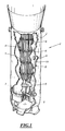
- FIG. 1 On the figure 1 the lower part of a steam generator of a pressurized water nuclear reactor generally designated 1 is shown.
- the steam generator 1 comprises, in a conventional manner, a substantially cylindrical pressure envelope 2 inside which a bundle shell 3 containing a bundle of tubes 4 of the steam generator 1 is coaxially disposed.
- the bundle of tubes 4 consists of a very large number of U-bent tubes 5, each having two straight branches which are engaged and fixed at their end in a tubular plate 6 fixed to the lower part of the generator pressure envelope.
- the pressure jacket 2 is connected to a hemispherical bottom delimiting a water box 7 in two parts.
- spacer plates 8 Inside the bundle shell 3 are fixed, in successive positions along the height of the bundle, spacer plates 8 intended to hold the branches of the tubes 5 of the bundle 4 to prevent them from vibrating during the operation of the generator. of steam.
- Each of the spacer plates 8 is pierced with a network of openings similar to the network of openings passing through the tubular plate 6 in which the ends of the tubes 5 of the bundle 4 are fixed.
- the straight branches of the tubes 5 of the bundle are engaged in aligned openings of spacer plates 8 spaced in the longitudinal direction of the tube 5.
- feed water of the steam generator 1 is introduced inside the pressure envelope 2 so as to be able to circulate from below upwards, inside the bundle envelope 3 in contact with the outer surface of the tubes 5.
- the feed water circulating in contact with the tubes is heated, then vaporizes.
- the steam produced is recovered at the top of the steam generator to be sent to the turbine of the nuclear reactor.
- the feed water recovered at the condenser of the turbine is returned to the steam generator and the circulation of the feed water is ensured by the secondary circuit of the nuclear reactor.
- the circulating water in the secondary circuit and inside the secondary part of the steam generator, in contact with the outer surface of the tubes 5 of the bundle 4, is charged with impurities such as oxides which can be deposited in the form of sludge on the upper surface of the tube plate 6 and also on the spacer plates 8, in particular in the interstices between the tubes 5 and the openings of these spacer plates 8 which must ensure the maintenance of the tubes 5 and the passage of the supply water in contact with the outer surface of said tubes 5.
- impurities such as oxides which can be deposited in the form of sludge on the upper surface of the tube plate 6 and also on the spacer plates 8, in particular in the interstices between the tubes 5 and the openings of these spacer plates 8 which must ensure the maintenance of the tubes 5 and the passage of the supply water in contact with the outer surface of said tubes 5.
- an appropriate tool not shown, and substantially at the level of the spacer plate 8 to be cleaned is pierced, an orifice 9 in the pressure envelope 2 and an orifice 10 in the bundle envelope 3.
- the orifice 9 will be referred to as the external orifice 9
- the orifice 10 will be called internal orifice 10.
- These respectively internal 9 and external 10 orifices are also commonly designated by the term "inspection holes”.
- the internal orifice 10 is located in the axis of the external orifice 9 and has a diameter substantially equal to or greater than this external orifice 9.
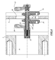
- the internal orifice 10 formed in the bundle envelope 3 is closed by means of a closure device according to the invention and designated as a whole by reference 20.
- This closure device 20 comprises a shaft 21 having on its external surface a thread 21a and a nut 22 intended to cooperate with the thread 21a of the shaft 21.
- the closure device 20 also comprises a pair of lower half-flanges, respectively 25 and 26, and a pair of upper half-flanges, respectively 27 and 28.
- the pair of lower half-flanges 25 and 26 is disposed between the pair upper half flanges 27 and 28.
- the two pairs of half-flanges are displaceable by substantially 180 ° rotation of the shaft 21, as will be seen later, between a low insertion position in the orifices 9 and 10, as shown in figure 3 , and wherein the upper half-flanges 27 and 28 are opposite the lower half-flanges 25 and 26, and an upper position, shown in FIG. figure 4 , in which the upper half-flanges 27 and 28 are opposed to the lower half-flanges 25 and 26. In these positions, the half-flanges 25, 26, 27 and 28 are spaced and parallel to each other.
- Each pair of half-flanges comprises, with respect to the bundle sheath 3, that is to say in the position corresponding to the clamping position shown in FIG. figure 4 , an inner half-flange 25 and 27 to said bundle envelope 3 and an outer half-flange 26 and 28 to said bundle envelope 3.
- the inner half-flange 27 of the pair of upper half-flanges 27 and 28 is integral in rotation and in translation of the shaft 21, for example by welding.
- the end of the shaft 21 comprises, for this purpose, a holding member in rotation of the inner half-flange 27, constituted for example by a square or a hexagonal flange 23.
- the outer half-flange 28 of this pair of half -flasks 27 and 28 is integral in rotation and free in translation with the shaft 21.
- this shaft 21 comprises two longitudinal and parallel flats 21b, as shown in FIG. figure 2 .
- the shaft 21 comprises translation locking means of the lower half-flanges 25 and 26 during the introduction into the orifices 9 and 10. These locking means are formed for the inner half-flange 25 by a transverse notch 24a formed on the outer surface of the shaft 21 ( figures 3 and 4 ) and for the outer half-flange 26 also by a transverse notch 24b formed on the outer surface of said shaft 21 ( figures 3 and 4 ).
- the surface portions facing the inner half-flanges 25 and 27 and the facing surface portions of the outer half-flanges 26 and 28 respectively of the pairs of lower half-flanges 25 and 26 and upper and lower 27 and 28 comprise bearing surfaces and complementary interlocking means.
- These complementary nesting means The type of tenon-mortise are formed for example by male-female V that ensure proper alignment and interlocking.
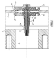
- the closure device is introduced into the external orifice 9, then into the internal orifice 10 with the upper half-flanges 27 and 28 in the lower position in which the half-flanges 25, 26, 27 and 28 are spaced apart and parallel to each other. In this insertion position, the lower half-flanges 25 and 26 are locked in translation by the notches 24a and 24b, respectively.
- the inner half-flanges 25 and 27 of the two pairs of half-flanges, respectively lower 25 and 26 and upper 27 and 28, are placed inside the bundle envelope 3 and the outer half-flanges 26 and 28 of the two pairs of half-flanges, respectively lower 25 and 26 and upper 27 and 28, are placed outside this bundle envelope 3, as shown in FIG. figure 3 .
- the shaft 21 is rotated substantially 180 ° about its axis which has the effect of releasing in translation the pair of lower half-flanges 25 and 26 due to the rotation of the notches 24a and 24b and which also effect of placing the pair of upper half-flanges 27 and 28 in the up position as shown in FIG. figure 4 .
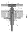
- the nut 22 is driven in rotation and this nut 22 by moving on the shaft 21, squeezes, on the one hand, the lower half-flanges 25 and 26 and, on the other hand, the upper half-flanges 27 and 28 on the peripheries disposed on either side of the internal orifice 10 in order to close off said internal orifice of the bundle sheath 3.
- the half-flanges 25 and 27 and the half-flanges 26 and 28 are positioned relative to each other through the support surfaces and complementary engagement means.
- the bearing surfaces of the half-flanges 25 and 27 on the inner periphery of the inner orifice 10 and the bearing surfaces of the half-flanges 26 and 28 on the periphery exterior of said inner orifice 10 substantially conform to the shape of the bundle envelope 3, as shown in FIG. figure 5 .
- the verification of the correct assembly can be performed by measuring the dimension of the end of the shaft 21 relative to the outside of the pressure envelope 2. This rating is reliable because it has low tolerance and the slightest misalignment of two flanges, for example, can cause a great disparity.
- the nut 22 can be crimped onto the shaft 21.
- the installation or removal of the closure device 20 is carried out using a tooling generally designated by the reference 30 and which is shown in FIG. figure 6 .
- the means for supporting and driving in rotation of the shaft 21 comprise an axle 31 axially comprising a screw 32 for fastening to the shaft 21.
- this shaft 21 comprises an axial bore 33 whose entry is threaded for the tightening of the screw 32.
- the support and drive means also comprise a socket 34 of engagement on the shaft 21 in order to join in rotation the shaft 31 and the shaft 21 arranged end to end along their longitudinal axis .
- the longitudinal guiding means of the shaft 21 are formed by a sheath 35 inside which are placed the shaft 31 and the shaft 21 joined together.
- the rotational drive means of the nut 22 on the shaft 21 comprise a bushing 36 for fastening in rotation with said nut 22 and carried by the sleeve 35.
- the means for vertical displacement of the shaft 21 after the positioning of the inner half-flanges 25 and 27 and the outer half-flanges 26 and 28 on either side of the internal orifice 10 comprise an outer ring 40 mounted in the external orifice 9 and maintained on the pressure envelope 2 for example by screwing members, not shown.
- This outer ring 40 has an orifice 41 for guiding an inner ring 42 provided with a hole 43 for guiding the sheath 35.
- the sheath 35 is mounted freely in rotation and in translation in the orifice 43 of the inner ring 42 and the axis 31 is mounted also free to rotate and in translation in said sheath 35.
- the inner ring 42 is free only in rotation in the outer ring 40.
- the guide orifices 41 and 43 formed in the rings, respectively outer 40 and inner 42, are parallel and off-axis in an eccentric arrangement.
- the establishment of the closure device 20 with the tooling 30 is performed as follows.
- the closure device 20 is mounted on the tooling 30 by securing the shaft 31 with the shaft 21 by means of the screw 32.
- the shaft 21 is secured to the axis 31 in rotation by through the sleeve 34.
- the sleeve 36 carried by the sheath 35 is engaged on the nut 22 of the shaft 21.
- the assembly constituted by the closure device 20 and the tooling 30 is placed in the insertion position in the external orifice 9 of the pressure envelope 2 and the inner ring 42 is locked on the outer ring 40, by appropriate means, not shown, to maintain the insertion position.
- This assembly thus assembled is introduced into the external orifice 9 of the pressure envelope 2 and the outer ring 40 is locked onto said pressure envelope 2.
- the shaft 31 integral with the shaft 21 and the sheath 35 are pushed inside the inner ring 42 to obtain a given dimension between the face of the outer ring 40 and the end of the axis 31 to ensure the positioning of the inner half-flanges 25 and 27 and the outer half-flanges 26 and 28 on either side of the beam envelope 3.
- the two pairs of half-flanges, respectively lower 25 and 26 and higher 27 and 28 are in the introduction position shown in FIG. figure 3 in which the two lower half-flanges 25 and 26 are locked in translation on the shaft 21 by means of the notches 24a and 24b, respectively.
- the axis of the shaft 21 is positioned above the axis of the orifices 9 and 10 since the guide orifices 41 and 43 are off-axis with respect to each other, this allows the passage of the half-flanges 25 and 27 in the bundle shell 3.
- the inner ring 42 is rotated substantially 180 ° in the outer ring 40 which aligns the shaft 21 and the outer orifice 9 of the pressure envelope 2 to place the pairs of lower half-flanges 25 and 26 and above 27 and 28 in the clamping position, as shown in FIG. figure 4 .
- the shaft 31 is pulled outward also driving the sleeve 35 to bring the inner half-flanges 25 and 27 into contact with the inside of the bundle shell 3. These inner half-flanges 25 and 27 fit together one in the other. While maintaining the axis 31, the sleeve 35 is rotated which has the effect of screwing the nut 22 through the sleeve 36 and bringing the outer half-flanges 26 and 28 towards each other and that fit into each other. These outer half-flanges 26 and 28 are gradually applied against the bundle shell 3 and the lower half-flanges 25 and 26 and the upper half-flanges 27 and 28 clamp the peripheries arranged on either side of the internal orifice 10 for closing off this internal orifice 10.
- Crimping of the nut is performed, for example by means of a deformable cup not shown here, so as to immobilize it in rotation and in translation and to hold the shutter in place.
- the complete tooling 30 is not necessary and the rings, respectively outer 40 and inner 42, are not necessarily used.
- the device according to the invention can be used to close an orifice of an enclosure.
Landscapes
- Engineering & Computer Science (AREA)
- Physics & Mathematics (AREA)
- Thermal Sciences (AREA)
- Mechanical Engineering (AREA)
- General Engineering & Computer Science (AREA)
- Life Sciences & Earth Sciences (AREA)
- Sustainable Development (AREA)
- Sustainable Energy (AREA)
- High Energy & Nuclear Physics (AREA)
- Monitoring And Testing Of Nuclear Reactors (AREA)
- Pipe Accessories (AREA)
- Pressure Vessels And Lids Thereof (AREA)
Applications Claiming Priority (1)
| Application Number | Priority Date | Filing Date | Title |
|---|---|---|---|
| FR0754664A FR2915619B1 (fr) | 2007-04-24 | 2007-04-24 | Dispositif et procede d'obturation d'un orifice d'une enveloppe de faisceau d'un generateur de vapeur d'un reacteur nucleaire a eau sous pression |
Publications (2)
| Publication Number | Publication Date |
|---|---|
| EP1998110A2 true EP1998110A2 (de) | 2008-12-03 |
| EP1998110A3 EP1998110A3 (de) | 2009-06-03 |
Family
ID=39027633
Family Applications (1)
| Application Number | Title | Priority Date | Filing Date |
|---|---|---|---|
| EP08103430A Withdrawn EP1998110A3 (de) | 2007-04-24 | 2008-04-08 | Vorrichtung und Verfahren zum Abdichten einer Öffnung in der Strahlenhülle eines Dampfgenerators eines Druckwasserkernreaktors |
Country Status (5)
| Country | Link |
|---|---|
| US (1) | US20090060110A1 (de) |
| EP (1) | EP1998110A3 (de) |
| CN (1) | CN101295550A (de) |
| FR (1) | FR2915619B1 (de) |
| ZA (1) | ZA200803214B (de) |
Cited By (1)
| Publication number | Priority date | Publication date | Assignee | Title |
|---|---|---|---|---|
| US10302598B2 (en) | 2016-10-24 | 2019-05-28 | General Electric Company | Corrosion and crack detection for fastener nuts |
Families Citing this family (2)
| Publication number | Priority date | Publication date | Assignee | Title |
|---|---|---|---|---|
| CN114283954B (zh) * | 2021-12-23 | 2024-12-31 | 中国核动力研究设计院 | 一种反应堆卡轴事故安全分析方法及装置 |
| CN114593408B (zh) * | 2022-02-22 | 2023-10-24 | 哈电集团(秦皇岛)重型装备有限公司 | 一种蒸汽发生器管束套筒与管座密封盘的装配装置及方法 |
Family Cites Families (6)
| Publication number | Priority date | Publication date | Assignee | Title |
|---|---|---|---|---|
| US1500423A (en) * | 1924-07-08 | Handhole closure | ||
| US1649720A (en) * | 1926-10-25 | 1927-11-15 | Moffitt Frank | Handhole plate |
| DE2948663C2 (de) * | 1979-12-04 | 1983-01-13 | Brown Boveri Reaktor GmbH, 6800 Mannheim | Verfahren zum Verschließen einer im Flansch eines Reaktordruckbehälters angebrachten Gewindebohrung und Vorrichtung zur Durchführung des Verfahrens |
| US4454957A (en) * | 1982-12-20 | 1984-06-19 | Power Cutting Incorporated | Self-locking sealing plug and installing method |
| US4954312A (en) * | 1988-12-15 | 1990-09-04 | Combustion Engineering, Inc. | Remotely installed steam generator nozzle dam system |
| US5251241A (en) * | 1992-08-28 | 1993-10-05 | Westinghouse Electric Corp. | Nuclear steam generator wrapper closure assembly and method of installing same |
-
2007
- 2007-04-24 FR FR0754664A patent/FR2915619B1/fr not_active Expired - Fee Related
-
2008
- 2008-04-08 EP EP08103430A patent/EP1998110A3/de not_active Withdrawn
- 2008-04-11 ZA ZA200803214A patent/ZA200803214B/xx unknown
- 2008-04-23 US US12/108,193 patent/US20090060110A1/en not_active Abandoned
- 2008-04-23 CN CNA2008100932123A patent/CN101295550A/zh active Pending
Cited By (1)
| Publication number | Priority date | Publication date | Assignee | Title |
|---|---|---|---|---|
| US10302598B2 (en) | 2016-10-24 | 2019-05-28 | General Electric Company | Corrosion and crack detection for fastener nuts |
Also Published As
| Publication number | Publication date |
|---|---|
| ZA200803214B (en) | 2009-09-30 |
| EP1998110A3 (de) | 2009-06-03 |
| FR2915619A1 (fr) | 2008-10-31 |
| US20090060110A1 (en) | 2009-03-05 |
| FR2915619B1 (fr) | 2009-08-21 |
| CN101295550A (zh) | 2008-10-29 |
Similar Documents
| Publication | Publication Date | Title |
|---|---|---|
| EP3377795B1 (de) | Abdichtungsvorrichtung zwischen einem rohr und einer durch dieses rohr durchgehenden säule, verfahren zur montage davon | |
| EP0633427A1 (de) | Wärmetauscher mit U-Rohrbündel und schwingungsneutralisierenden Stangen zwischen dem gekrümmten Teil | |
| FR2599463A1 (fr) | Bouchon de tube mecanique double | |
| WO2010072949A1 (fr) | Obturateur etanche d'une ouverture d'une tubulure de jonction d'une enceinte et d'une canalisation, notamment d'un generateur de vapeur d'un reacteur nucleaire a eau sous pression | |
| FR2705046A1 (fr) | Equipement interne pour le soudage bout à bout par faisceau d'électrons de deux pièces annulaires et utilisation. | |
| FR2585817A1 (fr) | Procede et dispositif de traitement de surface pour les echangeurs de chaleur | |
| EP0005670B1 (de) | Vorrichtung zum Dichten eines Leckes in einem geraden Teil eines Wärmetauscherrohres | |
| FR2581471A1 (fr) | Structure expansible de support de tubes avec barres antivibrations pour generateur de vapeur de centrale nucleaire | |
| EP1998110A2 (de) | Vorrichtung und Verfahren zum Abdichten einer Öffnung in der Strahlenhülle eines Dampfgenerators eines Druckwasserkernreaktors | |
| EP0300845A1 (de) | Vorrichtung für schwingungsneutralisierendes Festsetzen von Teilen einer Einrichtung und insbesondere schwingungsneutralisierende Stangen für Rotoren eines Dampferzeugers | |
| FR2895790A1 (fr) | Dispositif et procede d'intervention dans une boite a eau d'un echangeur de chaleur. | |
| EP0012672B1 (de) | Demontierbare Befestigungsvorrichtung eines elektrischen Widerstandsheizkörpers im Druckausgleichbehälter eines Kernreaktors | |
| FR2637722A1 (fr) | Bouchon d'obturation d'un tube de generateur de vapeur et procedes de montage et de demontage de ce bouchon | |
| FR2490393A1 (fr) | Assemblage combustible reconstituable pour un reacteur nucleaire | |
| EP0186536B1 (de) | Apparat zum Entfernen von Schlamm für eine Reinigungseinrichtung von einer Dampferzeugerrohrplatte und Dampferzeuger mit solchem Apparat | |
| FR2693129A1 (fr) | Outillage pour le traitement électrochimique de la surface interne d'un tube. | |
| FR2707373A1 (fr) | Dispositif de maintien radial de l'enveloppe de faisceau et des plaques-entretoises d'un générateur de vapeur. | |
| FR2551248A1 (fr) | Dispositif d'assemblage detachable pour ensembles d'elements combustibles nucleaires | |
| EP0648974A1 (de) | Radial Haltevorrichtung der Rohrbundelhülle und Rohrabstandplatten eines Dampferzeuger durch elastische Anschläge | |
| EP0173586A1 (de) | Wärmetauscher mit Rohrbündel, von einer zylindrischen Hülle umgeben, welche radial in einer äusseren Hülle festgehalten wird | |
| FR3154534A1 (fr) | Dispositif de maintien de deux éléments rapportés l'un sur l'autre, notamment dans un réacteur nucléaire compact | |
| FR2745960A1 (fr) | Dispositif de raccordement electrique permettant de connecter plusieurs cables de derivation a partir d'un cable d'arrivee | |
| FR2699984A1 (fr) | Procédé et dispositif pour la réparation, en charge, de canalisations en matière plastique. | |
| FR2750790A1 (fr) | Reacteur nucleaire comportant une cuve dans laquelle est dispose le coeur du reacteur et procede de refroidissement du coeur du reacteur a l'arret | |
| EP2681489B1 (de) | Verfahren zur reparatur eines druckhalters und vorrichtung zur umsetzung des verfahrens |
Legal Events
| Date | Code | Title | Description |
|---|---|---|---|
| PUAI | Public reference made under article 153(3) epc to a published international application that has entered the european phase |
Free format text: ORIGINAL CODE: 0009012 |
|
| AK | Designated contracting states |
Kind code of ref document: A2 Designated state(s): AT BE BG CH CY CZ DE DK EE ES FI FR GB GR HR HU IE IS IT LI LT LU LV MC MT NL NO PL PT RO SE SI SK TR |
|
| AX | Request for extension of the european patent |
Extension state: AL BA MK RS |
|
| PUAL | Search report despatched |
Free format text: ORIGINAL CODE: 0009013 |
|
| AK | Designated contracting states |
Kind code of ref document: A3 Designated state(s): AT BE BG CH CY CZ DE DK EE ES FI FR GB GR HR HU IE IS IT LI LT LU LV MC MT NL NO PL PT RO SE SI SK TR |
|
| AX | Request for extension of the european patent |
Extension state: AL BA MK RS |
|
| AKX | Designation fees paid | ||
| REG | Reference to a national code |
Ref country code: DE Ref legal event code: 8566 |
|
| STAA | Information on the status of an ep patent application or granted ep patent |
Free format text: STATUS: THE APPLICATION IS DEEMED TO BE WITHDRAWN |
|
| 18D | Application deemed to be withdrawn |
Effective date: 20091204 |