EP1998121A2 - Balustrade mit integriertem Wärmeabsorber zur Warmwasserbereitung - Google Patents
Balustrade mit integriertem Wärmeabsorber zur Warmwasserbereitung Download PDFInfo
- Publication number
- EP1998121A2 EP1998121A2 EP08157092A EP08157092A EP1998121A2 EP 1998121 A2 EP1998121 A2 EP 1998121A2 EP 08157092 A EP08157092 A EP 08157092A EP 08157092 A EP08157092 A EP 08157092A EP 1998121 A2 EP1998121 A2 EP 1998121A2
- Authority
- EP
- European Patent Office
- Prior art keywords
- safety member
- solar
- posts
- apt
- balustrade
- Prior art date
- Legal status (The legal status is an assumption and is not a legal conclusion. Google has not performed a legal analysis and makes no representation as to the accuracy of the status listed.)
- Withdrawn
Links
Images


Classifications
-
- F—MECHANICAL ENGINEERING; LIGHTING; HEATING; WEAPONS; BLASTING
- F24—HEATING; RANGES; VENTILATING
- F24D—DOMESTIC- OR SPACE-HEATING SYSTEMS, e.g. CENTRAL HEATING SYSTEMS; DOMESTIC HOT-WATER SUPPLY SYSTEMS; ELEMENTS OR COMPONENTS THEREFOR
- F24D17/00—Domestic hot-water supply systems
- F24D17/0015—Domestic hot-water supply systems using solar energy
- F24D17/0021—Domestic hot-water supply systems using solar energy with accumulation of the heated water
-
- F—MECHANICAL ENGINEERING; LIGHTING; HEATING; WEAPONS; BLASTING
- F24—HEATING; RANGES; VENTILATING
- F24S—SOLAR HEAT COLLECTORS; SOLAR HEAT SYSTEMS
- F24S20/00—Solar heat collectors specially adapted for particular uses or environments
- F24S20/60—Solar heat collectors integrated in fixed constructions, e.g. in buildings
- F24S20/62—Solar heat collectors integrated in fixed constructions, e.g. in buildings in the form of fences, balustrades or handrails
-
- F—MECHANICAL ENGINEERING; LIGHTING; HEATING; WEAPONS; BLASTING
- F24—HEATING; RANGES; VENTILATING
- F24S—SOLAR HEAT COLLECTORS; SOLAR HEAT SYSTEMS
- F24S80/00—Details, accessories or component parts of solar heat collectors not provided for in groups F24S10/00-F24S70/00
- F24S80/30—Arrangements for connecting the fluid circuits of solar collectors with each other or with other components, e.g. pipe connections; Fluid distributing means, e.g. headers
-
- F—MECHANICAL ENGINEERING; LIGHTING; HEATING; WEAPONS; BLASTING
- F24—HEATING; RANGES; VENTILATING
- F24S—SOLAR HEAT COLLECTORS; SOLAR HEAT SYSTEMS
- F24S20/00—Solar heat collectors specially adapted for particular uses or environments
- F24S20/04—Solar heat collectors specially adapted for particular uses or environments for showers
-
- F—MECHANICAL ENGINEERING; LIGHTING; HEATING; WEAPONS; BLASTING
- F24—HEATING; RANGES; VENTILATING
- F24S—SOLAR HEAT COLLECTORS; SOLAR HEAT SYSTEMS
- F24S40/00—Safety or protection arrangements of solar heat collectors; Preventing malfunction of solar heat collectors
- F24S40/80—Accommodating differential expansion of solar collector elements
-
- Y—GENERAL TAGGING OF NEW TECHNOLOGICAL DEVELOPMENTS; GENERAL TAGGING OF CROSS-SECTIONAL TECHNOLOGIES SPANNING OVER SEVERAL SECTIONS OF THE IPC; TECHNICAL SUBJECTS COVERED BY FORMER USPC CROSS-REFERENCE ART COLLECTIONS [XRACs] AND DIGESTS
- Y02—TECHNOLOGIES OR APPLICATIONS FOR MITIGATION OR ADAPTATION AGAINST CLIMATE CHANGE
- Y02B—CLIMATE CHANGE MITIGATION TECHNOLOGIES RELATED TO BUILDINGS, e.g. HOUSING, HOUSE APPLIANCES OR RELATED END-USER APPLICATIONS
- Y02B10/00—Integration of renewable energy sources in buildings
- Y02B10/20—Solar thermal
-
- Y—GENERAL TAGGING OF NEW TECHNOLOGICAL DEVELOPMENTS; GENERAL TAGGING OF CROSS-SECTIONAL TECHNOLOGIES SPANNING OVER SEVERAL SECTIONS OF THE IPC; TECHNICAL SUBJECTS COVERED BY FORMER USPC CROSS-REFERENCE ART COLLECTIONS [XRACs] AND DIGESTS
- Y02—TECHNOLOGIES OR APPLICATIONS FOR MITIGATION OR ADAPTATION AGAINST CLIMATE CHANGE
- Y02B—CLIMATE CHANGE MITIGATION TECHNOLOGIES RELATED TO BUILDINGS, e.g. HOUSING, HOUSE APPLIANCES OR RELATED END-USER APPLICATIONS
- Y02B10/00—Integration of renewable energy sources in buildings
- Y02B10/70—Hybrid systems, e.g. uninterruptible or back-up power supplies integrating renewable energies
-
- Y—GENERAL TAGGING OF NEW TECHNOLOGICAL DEVELOPMENTS; GENERAL TAGGING OF CROSS-SECTIONAL TECHNOLOGIES SPANNING OVER SEVERAL SECTIONS OF THE IPC; TECHNICAL SUBJECTS COVERED BY FORMER USPC CROSS-REFERENCE ART COLLECTIONS [XRACs] AND DIGESTS
- Y02—TECHNOLOGIES OR APPLICATIONS FOR MITIGATION OR ADAPTATION AGAINST CLIMATE CHANGE
- Y02E—REDUCTION OF GREENHOUSE GAS [GHG] EMISSIONS, RELATED TO ENERGY GENERATION, TRANSMISSION OR DISTRIBUTION
- Y02E10/00—Energy generation through renewable energy sources
- Y02E10/40—Solar thermal energy, e.g. solar towers
Definitions
- the present invention refers to a system for extracting thermal energy from solar radiation.
- a solar-powered system for hot water production is constituted by various units, each having a specific function:
- a solar collector functions substantially as heat generator and comprises a solar absorber, constituted by a black collecting plate, inside which a pipe bundle is inserted in which a thermal carrier fluid flows.
- the absorber thanks to specific treatments operated onto its surface, filters the infrared component of the solar radiation, component which operates the heating of the thermal carrier fluid.
- the pipe bundle can be made of materials endowed with excellent heat transmittance, like e.g. sheet metal, aluminium or copper.
- the assembly constituted by absorber and pipe bundle is usually enclosed in a container having a glazed surface in which it is present an insulating material, like e.g. glass wool or polyurethane.
- the container, or frame is usually made of aluminium or synthetic material, consistent sturdiness and stability to the collector.
- the insulating material present therein limits its thermal losses.
- the glazed surface allows solar radiation to reach the absorber, maximally preventing possible refractions.
- the thermal carrier fluid is generally additioned with anti-freeze in order not to freeze up during winter season (usually glycolated water is employed).
- the solar collector is connected to a hydraulic circuit which has the function of carrying the thermal carrier fluid inside a reservoir tank, or boiler, containing sanitary water to be heated.
- the forced circulation system substantially implies the use of a circulation pump and an electronic control unit regulating the pump starting and stopping on the basis of the temperature difference, detected by suitable probes, between the thermal carrier fluid at the collector outlet and the sanitary water held inside the boiler.
- the natural circulation system instead, the motion of the thermal carrier fluid inside the circuit is induced by the heating of the fluid itself.
- the hot fluid by being - volumes being equal - lighter than the cooler fluid, tends to rise, thereby inducing a circulation which then fosters heat conveyance to the sanitary water inside the boiler.
- the natural circulation system is, as it is obvious, much less complex than the forced circulation system, and therefore less expensive, as it can do without components such as the circulation pump and the control unit.
- the natural circulation system is much less performing: for instance, the fluid flow rate cannot be adjusted and, therefore, the heat transfer occurring both in the absorber and in the boiler cannot be optimized.
- the boiler location should be higher and as near as possible to the solar collector, and, if the latter is located outside, stored energy is not efficiently maintained, as it tends to be dissipated into the environment owing to possible bad weather and sudden changes in temperature between day and night.
- the "vacuum" solar collectors are expressly made to limit heat dissipation to the outside. They appear as glass pipes containing a heat-absorbing element and a thermal carrier fluid, inside which air pressure is greatly reduced, in a manner such as to limit just heat dissipation.
- the heating system employing this type of collectors is in all similar to the one described above, be it of forced circulation or of natural circulation type.
- collectors are usually assembled so as to give them a tilt such as to follow more or less optimally the pattern of the solar path, both in winter and in summer.
- the collectors may be installed on the roof, or freely positioned (e.g., in the garden) when equipped with suitable assembling structures, ground-located in order to give them a determined tilt degree.
- the technical problem solved by the present invention is to overcome the above-mentioned drawbacks. This is obtained by providing a system according to claim 1.
- the present invention by overcoming the mentioned problems of the known art, provides numerous and evident advantages.
- the system subject-matter of the present invention provides the use of one or more solar absorbers vertically housed inside a safety balustrade firmly fastened to the balcony floor.
- the system subject-matter of the present invention could provide the integration of all the regulation and safety devices inside the balustrade structure.
- a further advantage of the present invention is to give owners of numerous dwelling units the opportunity to make use of a solar-powered system even in case no sufficient space is available for connectors assembling, or no owned pitches/cover terraces are available.
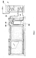
- FIG 1 it is shown in a front view a safety member 3, fastened on a floor 8 in correspondence of an external prospect present on a building.
- said safety member is made, by way of example and not for limitative purposes, by a balustrade, it also denoted by 3.
- Said balustrade 3 houses thereinside, in the manner that will be detailed hereinafter, one or more solar absorbers.
- said balustrade 3 comprises a structure for anchoring to said building.
- Said structure in the preferred embodiment given here solely by way of a non-limiting example, comprises a first plurality of posts 10, 11, 17, and an end post 16 fastened in correspondence of an end of the external prospect, said posts being vertically fastened on said floor 8 by connecting means 40.
- Said means 40 could vary, depending on the specific scenery in which said balustrade is installed.
- said posts are anchored onto the floor by means of bolts, them also denoted by 40.
- Each pair of consecutive posts of the first plurality are connected by a solar collector 30, fastened thereto by means of fastening screws 131 or equivalent means.
- the number of posts to be assembled of said first plurality and therefore the number of solar collectors, will vary according to the specific case, e.g. according to the length of the external prospect.
- Said solar collector 30 comprises a first outer panel 12, preferably facing the Sun rays, having a plate 15 of high-transmittance material in order to prevent undesired Sun rays reflections.
- said plate is made, by way of a non-limiting example, of high-Iron, high-transmittance solar glass.
- said plate could be made of safety glass, which has lower transmittance than the solar glass, but certainly entails a higher safety, above all in case the prospect of the building overlooks roads where pedestrians go. Therefore, the selection of the material could depend on the specific scenery in which the balustrade is inserted.
- the posts of said first plurality 10, 11 and 17 are equispaced thereamong in order to be connected by solar collectors 30, all alike thereamong (as the solar absorbers housed therein have all alike dimensions thereamong), whereas the distance between the end post 16 and the post 17 consecutive thereto will vary according to the specific length of the prospect on which the balustrade 3 is to be installed.
- a solar collector 30 could have dimensions excessive or insufficient to connect said end post 16 to the consecutive post 17. Therefore, in this case the posts 16 and 17 are connected by a dummy collector 100, substantially alike the solar collector 30, differing in that no solar absorber is present thereinside.
- the solar glass is preferably replaced by an aluminium panel 101. Therefore, the dummy collector 100, integrated into the balustrade without any aesthetic penalization, has the property of having a length defined according to the specific length of the prospect, in order to assemble the entire balustrade thereon without having composition problems, thereby guaranteeing safety.
- the balustrade 3 further comprises a handrail pipe 90, which runs along all of its horizontal development and is fastened at a free end of each vertical post.
- said handrail pipe is connected to each post by the insertion inside through members 95, each through member fastened to a respective post by means of fastening screws 96 or equivalent means.
- said collector 30 comprises a containment frame 50, of substantially U-shaped section, having two opposite vertical frames, each one fastened to a respective post, and two opposite faces (not shown in figure) parallel to the floor 8, assuring the collector closure topwise and bottomwise.
- a containment frame 50 could be fastened to the posts by fastening screws.
- each vertical face will be fastened to a respective post by a pair of top screws and a pair of bottom screws (this latter pair not shown in figure).
- a glass-holding frame 80 To said containment frame 50 it is fastened, along all of a free edge 70 thereof, a glass-holding frame 80, in an embodiment given herein by way of example and not for limitative purposes.
- the solar glass could also be integrated in a glass-holding frame containing and supporting also the absorber panel and the insulation, all inserted as a single body in the frame 50.
- said glass-holding frame is fastened to the containment frame, by way of a non-limiting example, by fastening screws 60.
- said solar glass plate 15 To the glass-holding frame it is connected said solar glass plate 15.
- the glass-holding frame operates with the solar glass a pressure-type connection, but this type of connection is merely exemplary: there might be other connection modes or other technical solutions, whose selection and technical implementation is deemed within the reach of a person skilled in the art. Therefore, the panel 12 comprises the glass-holding frame 80 (which also performs the aesthetical function of solar glass "frame”) and the solar glass plate 15.
- said collector further comprises a cover panel 13. It is fastened to the containment frame 50 along all of a free edge 57 thereof by a connection operated, by way of a non-limiting example, by fastening screws 61.
- a solar absorber 5 fastened to the balustrade in a vertical position with respect to the floor by means of, by way of a non-limiting example, four fastening (anchoring) clips, of which two positioned bottomwise and two positioned topwise, the latter shown in figure and denoted by reference numbers 58, 59, said clips being in turn bolted to the containment frame 50.
- thermal carrier fluid (not depicted in figure) is apt to flow.
- a thermal insulation mat 81 is placed inside the compartment 14, and precisely between the absorber 5 and the cover panel 13.
- the absorber 5 is connected in series to a consecutive absorber 5'. Therefore, on the post 10 and the containment frame 50 (and generally on any post and containment frame of the balustrade) there are obtained openings 67 to allow passage of the absorber 5 in correspondence of the connection with the successive absorber 5'. In particular, for each absorber there will be obtained, on a respective post, a top opening and a bottom opening (the latter not shown in figure).
- a top opening and a bottom opening the latter not shown in figure.
- FIG 2 it is shown an embodiment of a system 1 for hot water production, as subject-matter of the present invention.
- a natural circulation hydraulic circuit 6 communicating with the battery constituted by the solar absorbers 5 and 5' connected in series therebetween and housed inside the balustrade 3. Inside said hydraulic circuit it is apt to flow the thermal carrier fluid which is heated up in the transit through said solar absorbers.
- said hydraulic circuit comprises a delivery piping 31, a return piping 35, forming a closed circuit with a piping (not shown in figure) housed inside a boiler 200 apt to foster heat conveyance to sanitary water held in said boiler.
- the return piping 35 is connected to a bottom connection 96 of the absorber 5'.
- the heated thermal carrier fluid will in fact tend to rise (by being lighter than the cooler fluid); therefore the return piping 35 shall necessarily intercept the absorbers in a position located bottomwise with respect to the delivery piping 31.
- the delivery piping 5 has to be connected to the absorber 5 in correspondence of a connection 97 thereof, or in a position opposite to the connection point 96 of the return piping.
- a portion 37 of the piping could advantageously be housed inside the handrail pipe 90, which internally is hollow, thereby guaranteeing a further integration of system members into the balustrade 3.
- a heat-insulating sheath (not shown in figure) is present, in order to limit undesired thermal dissipation.
- said portion could alternatively be advantageously housed inside the solar collectors, and in particular said portion will cross in series all the collectors of the balustrade, inside the thermal insulation mats of each solar collector.
- suitable holes should be obtained on the posts and containment frames of each collector, in order to allow just the passage of the piping.
- the dummy collector 100 remains empty thereinside.
- FIG 3 it is shown a variant of the system 1 subject-matter of the present invention, which uses a forced circulation hydraulic circuit.
- the system remains in substance alike the aforedescribed one, with the difference that the hydraulic circuit now comprises means 33 for moving the fluid and safety and control means 34.
- Said moving and control means used in a forced-circulation thermal solar circuit are well known in the state of the art and frequently used; hence, their selection and sizing, depending on the specific case, are deemed to be within the reach of a person skilled in the art and will not be delved into hereinafter.
- said moving means 33 comprises a circulator 140
- said safety and control means comprise an expansion vessel 141, as well as an electronic control unit 144 apt to receive and process data sent by probes (not shown in the figure), apt to detect the temperatures of the boiler 200 and of the thermal carrier fluid at the outlet of the solar absorbers, in order to stop or not to stop the circulator operation, or to notice the user with a visual alarm message, should the detected temperatures reach or exceed a safety limit value.
- Said means 33 and 34 are positioned along the return piping 35, upstream of the connection 96 of said piping with the absorber 5'. Therefore, as shown in figure, they are advantageously housed inside the dummy collector 100, thus effecting the utmost architectural integration, thereby fostering a greater simplicity in the assembling, in conjunction with a sensible decrease of the dimensions.
- the system subject-matter of the present invention also provides a further preferred embodiment (not shown in figure).
- a further preferred embodiment By varying the mutual position of the bottom and top openings in the posts and in the containment frames through which there occurs the connecting between an absorber and two absorbers successive thereto, in particular by advancing toward the prospect the pair of bottom openings, and withdrawing in the opposite direction the pair of top openings, it is possible to adjust the tilt of the absorber with respect to the containment frame containing it, in order to improve captation of the solar radiation incident thereon.
- the final tilt of the heat absorbers could then be advantageously determined by suitably adjusting the three relative tilts described above: first tilt of the solar absorbers with respect to the respective containment frames, second tilt of the containment frames with respect to the respective pairs of posts, third tilt of the posts with respect to the vertical to the floor on which they are fastened.
- balustrade it would likewise be insertable an absorber member, not necessarily solar, suitable e.g. for power production, which absorber member might therefore not necessarily contain a thermal carrier fluid.
Landscapes
- Engineering & Computer Science (AREA)
- Chemical & Material Sciences (AREA)
- Life Sciences & Earth Sciences (AREA)
- Sustainable Development (AREA)
- Sustainable Energy (AREA)
- Thermal Sciences (AREA)
- Physics & Mathematics (AREA)
- Combustion & Propulsion (AREA)
- Mechanical Engineering (AREA)
- General Engineering & Computer Science (AREA)
- Building Environments (AREA)
- Buildings Adapted To Withstand Abnormal External Influences (AREA)
- Roof Covering Using Slabs Or Stiff Sheets (AREA)
- Thermotherapy And Cooling Therapy Devices (AREA)
Applications Claiming Priority (1)
| Application Number | Priority Date | Filing Date | Title |
|---|---|---|---|
| IT000292A ITRM20070292A1 (it) | 2007-05-28 | 2007-05-28 | Ringhiera con assorbitore termico integrato per la produzione di acqua calda. |
Publications (2)
| Publication Number | Publication Date |
|---|---|
| EP1998121A2 true EP1998121A2 (de) | 2008-12-03 |
| EP1998121A3 EP1998121A3 (de) | 2012-05-30 |
Family
ID=39731621
Family Applications (1)
| Application Number | Title | Priority Date | Filing Date |
|---|---|---|---|
| EP08157092A Withdrawn EP1998121A3 (de) | 2007-05-28 | 2008-05-28 | Balustrade mit integriertem Wärmeabsorber zur Warmwasserbereitung |
Country Status (2)
| Country | Link |
|---|---|
| EP (1) | EP1998121A3 (de) |
| IT (1) | ITRM20070292A1 (de) |
Cited By (2)
| Publication number | Priority date | Publication date | Assignee | Title |
|---|---|---|---|---|
| EP2780647A4 (de) * | 2011-11-16 | 2015-12-23 | Babcock & Wilcox Co | Solarempfänger mit doppelt belichteter wärmeabsorptionsplatte |
| IT202200009542A1 (it) | 2022-05-10 | 2023-11-10 | Christoph Weithaler | Ringhiera per esterno di un edificio per esempio per balconi con un collettore solare |
Family Cites Families (8)
| Publication number | Priority date | Publication date | Assignee | Title |
|---|---|---|---|---|
| CA1132019A (en) * | 1978-03-06 | 1982-09-21 | Thomas P. Hopper | Solar collector of a liquid heat exchange type |
| FR2432146A1 (fr) * | 1978-07-24 | 1980-02-22 | Prunier Jean | Dispositif de main courante pour le captage d'energie solaire |
| DE3013986A1 (de) * | 1980-04-11 | 1981-10-15 | Gerbert, Heinz, Dipl.-Ing., 7951 Erlenmoos | Luftwaerme- und sonnenkollektor in form eines energiezaunes o.dgl. |
| DE3106253A1 (de) * | 1981-02-20 | 1982-09-09 | Heinz 4500 Osnabrück Spieker | Waermeabsorber-gelaender oder -zaun |
| EP0330701A3 (de) * | 1984-09-18 | 1989-10-04 | Sharp Kabushiki Kaisha | Wärme-Kollektor |
| DE4322653C2 (de) * | 1993-07-07 | 1995-08-31 | Elektro Loewer | Brüstungselement |
| DE29811647U1 (de) * | 1998-06-30 | 1998-10-08 | Bock, Manfred, Dipl.-Ing., 30455 Hannover | Vorgefertigtes Architekturelement |
| JP2002106974A (ja) * | 2000-07-24 | 2002-04-10 | Nishimatsu Constr Co Ltd | 太陽熱温水器および太陽熱温水システム |
-
2007
- 2007-05-28 IT IT000292A patent/ITRM20070292A1/it unknown
-
2008
- 2008-05-28 EP EP08157092A patent/EP1998121A3/de not_active Withdrawn
Cited By (2)
| Publication number | Priority date | Publication date | Assignee | Title |
|---|---|---|---|---|
| EP2780647A4 (de) * | 2011-11-16 | 2015-12-23 | Babcock & Wilcox Co | Solarempfänger mit doppelt belichteter wärmeabsorptionsplatte |
| IT202200009542A1 (it) | 2022-05-10 | 2023-11-10 | Christoph Weithaler | Ringhiera per esterno di un edificio per esempio per balconi con un collettore solare |
Also Published As
| Publication number | Publication date |
|---|---|
| ITRM20070292A1 (it) | 2008-11-29 |
| EP1998121A3 (de) | 2012-05-30 |
Similar Documents
| Publication | Publication Date | Title |
|---|---|---|
| CN104412047B (zh) | 中空玻璃式太阳能集热器与采用它的用太阳能供暖和降温的建筑物 | |
| EP2504636A1 (de) | Solarerhitzer mit koaxialröhren und nächtlicher kühlung | |
| NO156505B (no) | Varmesystem for bygninger,med en plateformet solfanger | |
| US4338917A (en) | Low temperature solar furnace and method | |
| US4387704A (en) | Multi-mode solar heat recovery device | |
| US20110005514A1 (en) | Solar thermal heating utilizing dynamic particle flow balancing | |
| US20110232213A1 (en) | Solar roofing assembly | |
| US20150214408A1 (en) | Solar water-collecting, air-conditioning, light-transmitting and power generating house | |
| EP1998121A2 (de) | Balustrade mit integriertem Wärmeabsorber zur Warmwasserbereitung | |
| US4465058A (en) | Solar energy air-heating system | |
| KR100801321B1 (ko) | 난간용 태양열 집열관을 이용한 난방 및 온수공급 시스템 | |
| CN102080432A (zh) | 与建筑一体化外遮阳抛物反射镜追日太阳能集热器 | |
| Saxena et al. | A review of recent patents on solar air heaters | |
| CN101606029A (zh) | 太阳能收集器 | |
| KR100675785B1 (ko) | 태양열 집열기 및 이를 이용한 난방장치 | |
| EP0004126A2 (de) | Sonnenkollektor | |
| US4353353A (en) | Low temperature solar furnace and method | |
| JP3544529B2 (ja) | 太陽熱集熱パネル | |
| EP2144013A1 (de) | Thermohydraulisches System und Betriebsverfahren davon | |
| WO2007045933A1 (en) | Pergola solar collector system constructed from long heating elements | |
| RU2738738C1 (ru) | Планарная кровельная панель с гофрированным тепловым фотоприёмником | |
| CN100380066C (zh) | 设置在阳台上的包括浴室和太阳暖房的太阳能集热装置 | |
| CN221255912U (zh) | 一种玻璃建筑屋顶 | |
| CN202048701U (zh) | 太阳能热水器 | |
| CN102312497A (zh) | 太阳能与建筑一体化幕墙系统及其安装施工方法 |
Legal Events
| Date | Code | Title | Description |
|---|---|---|---|
| PUAI | Public reference made under article 153(3) epc to a published international application that has entered the european phase |
Free format text: ORIGINAL CODE: 0009012 |
|
| AK | Designated contracting states |
Kind code of ref document: A2 Designated state(s): AT BE BG CH CY CZ DE DK EE ES FI FR GB GR HR HU IE IS IT LI LT LU LV MC MT NL NO PL PT RO SE SI SK TR |
|
| AX | Request for extension of the european patent |
Extension state: AL BA MK RS |
|
| PUAL | Search report despatched |
Free format text: ORIGINAL CODE: 0009013 |
|
| AK | Designated contracting states |
Kind code of ref document: A3 Designated state(s): AT BE BG CH CY CZ DE DK EE ES FI FR GB GR HR HU IE IS IT LI LT LU LV MC MT NL NO PL PT RO SE SI SK TR |
|
| AX | Request for extension of the european patent |
Extension state: AL BA MK RS |
|
| RIC1 | Information provided on ipc code assigned before grant |
Ipc: F24D 17/00 20060101ALI20120426BHEP Ipc: F24J 2/46 20060101AFI20120426BHEP Ipc: F24J 2/04 20060101ALI20120426BHEP |
|
| AKY | No designation fees paid | ||
| REG | Reference to a national code |
Ref country code: DE Ref legal event code: R108 |
|
| REG | Reference to a national code |
Ref country code: DE Ref legal event code: R108 Effective date: 20130206 |
|
| STAA | Information on the status of an ep patent application or granted ep patent |
Free format text: STATUS: THE APPLICATION IS DEEMED TO BE WITHDRAWN |
|
| 18D | Application deemed to be withdrawn |
Effective date: 20121201 |