EP1998150B1 - Cellule de pesage - Google Patents
Cellule de pesage Download PDFInfo
- Publication number
- EP1998150B1 EP1998150B1 EP20080007309 EP08007309A EP1998150B1 EP 1998150 B1 EP1998150 B1 EP 1998150B1 EP 20080007309 EP20080007309 EP 20080007309 EP 08007309 A EP08007309 A EP 08007309A EP 1998150 B1 EP1998150 B1 EP 1998150B1
- Authority
- EP
- European Patent Office
- Prior art keywords
- load cell
- cell according
- force
- deformation ring
- recess
- Prior art date
- Legal status (The legal status is an assumption and is not a legal conclusion. Google has not performed a legal analysis and makes no representation as to the accuracy of the status listed.)
- Not-in-force
Links
Images

Classifications
-
- G—PHYSICS
- G01—MEASURING; TESTING
- G01G—WEIGHING
- G01G3/00—Weighing apparatus characterised by the use of elastically-deformable members, e.g. spring balances
- G01G3/12—Weighing apparatus characterised by the use of elastically-deformable members, e.g. spring balances wherein the weighing element is in the form of a solid body stressed by pressure or tension during weighing
- G01G3/14—Weighing apparatus characterised by the use of elastically-deformable members, e.g. spring balances wherein the weighing element is in the form of a solid body stressed by pressure or tension during weighing measuring variations of electrical resistance
- G01G3/1402—Special supports with preselected places to mount the resistance strain gauges; Mounting of supports
- G01G3/141—Special supports with preselected places to mount the resistance strain gauges; Mounting of supports the supports being disc or ring shaped
-
- G—PHYSICS
- G01—MEASURING; TESTING
- G01L—MEASURING FORCE, STRESS, TORQUE, WORK, MECHANICAL POWER, MECHANICAL EFFICIENCY, OR FLUID PRESSURE
- G01L1/00—Measuring force or stress, in general
- G01L1/20—Measuring force or stress, in general by measuring variations in ohmic resistance of solid materials or of electrically-conductive fluids; by making use of electrokinetic cells, i.e. liquid-containing cells wherein an electrical potential is produced or varied upon the application of stress
- G01L1/22—Measuring force or stress, in general by measuring variations in ohmic resistance of solid materials or of electrically-conductive fluids; by making use of electrokinetic cells, i.e. liquid-containing cells wherein an electrical potential is produced or varied upon the application of stress using resistance strain gauges
- G01L1/2206—Special supports with preselected places to mount the resistance strain gauges; Mounting of supports
- G01L1/2231—Special supports with preselected places to mount the resistance strain gauges; Mounting of supports the supports being disc- or ring-shaped, adapted for measuring a force along a single direction
Definitions
- the invention relates to a load cell having an upper central force introduction part, which is connected to a lower annular Kraftaus effetsteil, and with a central recess surrounding a deformation ring which is formed between the force introduction part and the Kraftaus effetsteil and spaced by an annular groove for Kraftaus effetsteil, one to an axial Force introduction direction has transversely extending end face and is equipped with electromechanical transducers.
- the deformation ring is connected via a first pipe section with the force introduction part and a second pipe section with the Kraftaus effetsteil.
- the deformation ring has a lower end face and a parallel upper surface, both of which are equipped with electromechanical transducers in the form of strain gauges.
- the deformation ring deforms not only axially but also undergoes a rotation, with its lower part moves radially outward and its upper part radially inward. Therefore, the difference between the lower and upper deformations of the deformation ring is detected with the strain gauges applied to the two surfaces.
- This known load cell is disadvantageous in that its construction requires considerable effort.
- WO-0073757 discloses another known load cell.
- the invention is therefore based on the object to improve the aforementioned load cell.
- this load cell it is provided in this load cell according to the invention that the force introduction part and the force extraction part are connected by a radially outwardly and downwardly facing web, from the inside of the deformation ring extends radially inwardly and downwardly. This ensures that, when the force acting axially on the force introduction part, a rotation of the deformation ring is practically excluded and only the radial deformation of the force measurement is detected. Thus, the accuracy of the measurement is significantly increased because a caused by a rotation error source is excluded. Furthermore, the geometry of the load cell, its manufacture and the wiring of the strain gauges are relatively simple and the load cell has a smaller diameter at the same load.
- the deformation ring has a smaller axial length than the axial length of the Kraftaus effetsteils. It is also advantageous if the depth of the annular groove is substantially smaller than the depth of the recess. Finally, the deformation ring at its lower and inner end have an axially parallel wall portion, to which the electromechanical transducer, so expedient strain gauges are applied. As a supplement or alternative may also be considered to install electromechanical transducer on the face. It is also advantageous if the opening enclosed by the annular wall section has a smaller diameter than the recess.
- a particularly favorable design of the cup-shaped recess provides that it has an annular side wall which is inclined inwards and downwards, delimits the deformation ring on the inside and merges into the wall section. Then, at the transition from the side wall to the wall portion, a plate made of plastic may be inserted, which carries an electronic circuit electrically connected to the electromechanical transducers. In general, it further serves to eliminate any measurement errors, if according to the invention, the electromechanical transducers are mounted so that they have the same mutual distance and are arranged symmetrically about the axis of the load cell.
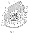
- the one-piece and round load cell 1 with axle 6 produced from a steel block by appropriate machining consists of an upper force introduction part 2, a lower, tubular Kraftaus Arthursteil 3 and a two parts connecting web 4, from the inside of a deformation ring 5 projects inwardly and downwardly.
- the force introduction part 2 has a flat surface 21, via which the axially applied force to be measured is introduced into the body 22 of the force introduction part.
- the outer contour of the body 22 is dovetail-shaped in the illustrated section and directed towards the axis 6 and in the lower portion 24, the outer contour follows a directed away from the axis 6 circular arc 25, which extends over slightly more than a right angle, so that it ends down practically transversely to the axis 6 to the outside. In about half of the circular arc of the body 22 goes into the annular web portion 41, which is bounded inside by a recess 7 in still closer detail.
- the web portion 41 widens to a solid intermediate piece 42, from the inside of the deformation ring 5 projects inwardly below, and the outside of an axially parallel outer wall 43 is limited.
- the intermediate piece 42 of the web 4 continues down into the tubular force discharge part 3.
- a ring 33 is formed, the axially parallel outer surface 35 is aligned with the outer wall 43.
- the axial length of the deformation ring 5 is smaller than the axial length of the Kraftaus effetteils 3rd
- the force discharge part 3 encloses a cup-shaped cavity 31, in which centrally the lower annular portion 51 of the deformation body 5 protrudes from above.
- the portion 51 terminates at the bottom with an annular surface 52 which extends transversely to the axis 6 and approximately at the level of the lower end of the recess 32.
- annular surface 52 which extends transversely to the axis 6 and approximately at the level of the lower end of the recess 32.
- Section 51 is spaced from the inner wall 36 of the force extraction part 3 by a dome shaped annular groove 38 formed on the one hand by the inner wall 36 and on the other hand by the flat outer surface of the section 51 which also has a depth smaller than the depth the recess 7 and only about half the height of the recess 7 plus a cylindrical bore 71 extends.
- the cavity 31 continues upward into the mentioned central and cylindrical bore 71, the annular side wall of which is formed by an axially parallel and annular wall portion 53 of the deformation ring 5.
- the bore 71 merges upward into the recess 7, which has an upper, circular and planar boundary surface 72 extending transversely symmetrically to the axis 6 and a side surface 74.
- the opening of the bore 71 enclosed by the wall section 53 has a diameter which is approximately half the total lateral extent of the load cell 1 and, in any case, smaller than the largest diameter of the recess 7.
- the side surface 74 closes at the top with an arc 75 Limiting surface 72, bounding the deformation ring 5 inwardly and connects to the bottom via a small shoulder 76 to the wall portion 53 at.
- the shoulder 76 is shaped so that a lightweight support plate 81 can be held on it, which carries on its underside a board 82 of an electronic circuit 80 with circuit elements 84.
- the circuit 80 may also have temperature, zero and characteristic adjustment elements. These are easily accessible from the outside by virtue of the downwardly open cavity 31.
- strain gauges At the axially parallel wall portion 53 are a plurality of strain gauges in the circumferential direction in the same applied at a mutual distance, and that near the lower edge to the annular surface 52.
- four strain gauges are provided, of which only the three strain gages 83, 85, 87 can be seen.
- the measurements of forces also give sufficient accuracy when only two strain gauges are used.
- a mounting hole 86 which is laterally introduced from the outside transversely to the axis 6 through the intermediate piece 42 and opens into the recess 7. Through the mounting hole 86 cables for power supply and signal transmission to the circuit 80 can be introduced. Finally, the downwardly basically open cavity 31 can be closed by an inserted membrane, so that the load cell 1 is then permanently protected from moisture and can also be used in explosion-proof rooms.
- the load cell 1 is characteristic that the principle axis-parallel power flow is deflected at the transition from the force introduction part 2 to 3 Kraftaustechnischtechnischsteil 3 by the web only slightly directionally outward, with the result that the deformation ring 5 predominantly a radially outwardly directed deformation, at least practical no twisting experiences.
- the perpendicular to the line passing through the centers of the curves 25 and 75 extends, forms to the axis 6 depending on the embodiment of the load cell an angle between about 20 ° and about 70 °.
- the greatest tensile stresses occur in the deformation ring and, on the other hand, the disturbing effects due to the introduction of force and force are smallest here.
- the load cell 1 is not only calibratable, that is, the measurements of an applied force remain within officially approved intervals, but also achieves an excellent close fault tolerance, which is about 0.01% to about 0.3% of the respective rated load lies. With the load cell 1 forces can be measured, ranging from about 10 tons to about 1000 tons and more, the concrete dimensional design of the load cell must be adjusted accordingly.
Landscapes
- Physics & Mathematics (AREA)
- General Physics & Mathematics (AREA)
- Measurement Of Force In General (AREA)
Claims (9)
- Cellule de pesage comprenant ane partie supérieure centrale d'introduction de force (2) qui est reliée à une partie inférieure annulaire de sortie de force (3), comprenant une bague de déformation (5) entourant un évidement central (7), laquelle est réalisée entre la partie d'introduction de force et la partie de sortie de force, est espacée de la partie d'introduction de force par une rainure annulaire (38), présente une surface frontale (52) s'étendant transversalement par rapport à une direction axiale d'introduction de force (6) et est équipée de convertisseurs (83, 85, 87) électromécaniques, caractérisée en ce que la partie d'introduction de force et la partie de sortie de force sont reliées par une nervure (4) orientée radialement vers l'extérieur et vers le bas, à partir du côté intérieur de laquelle s'étend la bague de déformation (5) radialement vers l'intérieur et vers le bas.
- Cellule de pesage selon la revendication 1, caractérisée en ce que la bague de déformation comprend à son extrémité inférieure et intérieure une portion de paroi (53) parallèle à l'axe, sur laquelle sont appliqués les convertisseurs électromécaniques.
- Cellule de pesage selon la revendication 2, caractérisée en ce que l'ouverture (71) entourée par la portion de paroi annulaire (53) présente un diamètre inférieur à celui de l'évidement (7).
- Cellule de pesage selon l'une quelconque ou plusieurs des revendications précédentes, caractérisée en ce que l'évidement en forme de cuvette (7) comprend une paroi latérale annulaire (74) qui est inclinée vers le bas et vers l'intérieur, délimite intérieurement la bague de déformation (5) et se prolonge par la portion de paroi (53).
- Cellule de pesage selon l'une quelconque ou plusieurs des revendications précédentes, caractérisée en ce que la profondeur de la rainure annulaire (38) est considérablement inférieure à la profondeur de l'évidement (7).
- Cellule de pesage selon l'une quelconque ou plusieurs des revendications précédentes, caractérisée en ce que des convertisseurs électromécaniques sont appliqués sur la surface frontale (52).
- Cellule de pesage selon l'une quelconque ou plusieurs des revendications précédentes, caractérisée en ce que les convertisseurs électromécaniques sont disposés de manière symétrique autour de l'axe (6) de manière à présenter des espacements mutuels identiques.
- Cellule de pesage selon l'une quelconque ou plusieurs des revendications précédentes, caractérisée en ce que la longueur axiale de la bague de déformation (5) est inférieure à la longueur axiale de la partie de sortie de force (3) .
- Cellule de pesage selon l'une quelconque des revendications 4 à 8, caractérisée en ce qu'une plaque de support (81) est insérée au niveau de la transition de la paroi latérale (74) à la portion de paroi (53), laquelle plaque de support porte un circuit électronique (80) connecté électriquement aux convertisseurs (83, 85, 87) électromécaniques.
Applications Claiming Priority (1)
| Application Number | Priority Date | Filing Date | Title |
|---|---|---|---|
| DE200710025474 DE102007025474B4 (de) | 2007-05-31 | 2007-05-31 | Wägezelle |
Publications (2)
| Publication Number | Publication Date |
|---|---|
| EP1998150A1 EP1998150A1 (fr) | 2008-12-03 |
| EP1998150B1 true EP1998150B1 (fr) | 2014-04-30 |
Family
ID=39720105
Family Applications (1)
| Application Number | Title | Priority Date | Filing Date |
|---|---|---|---|
| EP20080007309 Not-in-force EP1998150B1 (fr) | 2007-05-31 | 2008-04-14 | Cellule de pesage |
Country Status (3)
| Country | Link |
|---|---|
| EP (1) | EP1998150B1 (fr) |
| DE (1) | DE102007025474B4 (fr) |
| ES (1) | ES2478665T3 (fr) |
Families Citing this family (5)
| Publication number | Priority date | Publication date | Assignee | Title |
|---|---|---|---|---|
| DE102009002188A1 (de) * | 2009-04-03 | 2010-10-14 | Tecsis Gmbh | Kraftaufnehmer zur Messung von Stützkräften in einem Abstützelement |
| DE102014013042B4 (de) * | 2014-09-02 | 2016-03-10 | Schenck Process Gmbh | Kraftmessvorrichtung |
| DE102016118045B4 (de) | 2016-09-23 | 2024-08-14 | Minebea Intec GmbH | Querkraft-unempfindliche Messzelle |
| EP3671142B1 (fr) | 2018-12-20 | 2022-11-09 | Bizerba SE & Co. KG | Cellule de pesage et pied de pesage |
| EP3671141B1 (fr) * | 2018-12-20 | 2022-08-03 | Bizerba SE & Co. KG | Cellule de pesage et pied de pesage |
Family Cites Families (6)
| Publication number | Priority date | Publication date | Assignee | Title |
|---|---|---|---|---|
| US3520182A (en) * | 1967-06-05 | 1970-07-14 | Kelk Ltd George | Load cells |
| DE3714613A1 (de) | 1987-05-01 | 1988-11-17 | Helmut Dr Ing Gassmann | Waegezelle |
| DE4344565C1 (de) * | 1993-12-24 | 1995-03-23 | Schenck Ag Carl | Vorrichtung zum Messen von Lasten |
| DE4412377A1 (de) * | 1994-04-13 | 1995-10-19 | Hottinger Messtechnik Baldwin | Aufnehmer zum Messen von Belastungen |
| DE19611484A1 (de) | 1996-03-25 | 1997-10-02 | Schenck Process Gmbh | Wägezelle |
| EP1181514B1 (fr) * | 1999-06-01 | 2006-10-04 | Sartorius Hamburg GmbH | Diaphragme ondule a symetrie de revolution pour cellule de pesee |
-
2007
- 2007-05-31 DE DE200710025474 patent/DE102007025474B4/de not_active Expired - Fee Related
-
2008
- 2008-04-14 ES ES08007309.1T patent/ES2478665T3/es active Active
- 2008-04-14 EP EP20080007309 patent/EP1998150B1/fr not_active Not-in-force
Also Published As
| Publication number | Publication date |
|---|---|
| ES2478665T3 (es) | 2014-07-22 |
| EP1998150A1 (fr) | 2008-12-03 |
| DE102007025474A1 (de) | 2008-12-04 |
| DE102007025474B4 (de) | 2011-04-14 |
Similar Documents
| Publication | Publication Date | Title |
|---|---|---|
| EP2251661B1 (fr) | Dispositif de mesure de force | |
| EP2642255A2 (fr) | Appareil de mesure | |
| WO2017025428A1 (fr) | Capteur de force-couple ainsi que système d'extensomètre et ensemble de platines pour un capteur force-couple de ce type | |
| DE3544885A1 (de) | Kraftmesseinrichtung | |
| EP1998150A1 (fr) | Cellule de pesage | |
| DE202008017526U1 (de) | Modular aufgebaute Messachse | |
| EP0916077B1 (fr) | Capteur de force monolithique | |
| DE102008062249A1 (de) | Standfuss für ein Wägezelle | |
| DE102013012506A1 (de) | Stabförmiger Kraftaufnehmer mit verbessertem Verformungsverhalten | |
| EP1448961A1 (fr) | Support de plateau de balance dote d'une protection contre les surcharges | |
| DE102013012507B4 (de) | Stabförmiger Kraftaufnehmer mit vereinfachtem Abgleich | |
| DE102017104349A1 (de) | Wägezelle für eine Waage | |
| EP2254525A1 (fr) | Dispositif détecteur de forme tubulaire | |
| DE10224199A1 (de) | Kraft-Messdose | |
| EP1754030B1 (fr) | Securite antisurcharge pour element dynamometrique | |
| EP3671141B1 (fr) | Cellule de pesage et pied de pesage | |
| EP0338325B1 (fr) | Dispositif de mesure de force du type d'anneau à torsion | |
| DE102012005638B4 (de) | Messgerät | |
| WO1995008102A1 (fr) | Dispositif dynamometrique | |
| DE112015006374B4 (de) | Überlastverhinderungsmechanismus | |
| DE69316076T2 (de) | Magnetostriktiver Kraftwandler | |
| DE10055933A1 (de) | Aufnehmer zum Messen von Belastungen | |
| DE102014013042B4 (de) | Kraftmessvorrichtung | |
| DE2132012B2 (de) | Kraftmeßvorrichtung | |
| WO2007031111A1 (fr) | Axe de mesure de conception modulaire |
Legal Events
| Date | Code | Title | Description |
|---|---|---|---|
| PUAI | Public reference made under article 153(3) epc to a published international application that has entered the european phase |
Free format text: ORIGINAL CODE: 0009012 |
|
| AK | Designated contracting states |
Kind code of ref document: A1 Designated state(s): AT BE BG CH CY CZ DE DK EE ES FI FR GB GR HR HU IE IS IT LI LT LU LV MC MT NL NO PL PT RO SE SI SK TR |
|
| AX | Request for extension of the european patent |
Extension state: AL BA MK RS |
|
| 17P | Request for examination filed |
Effective date: 20090304 |
|
| AKX | Designation fees paid |
Designated state(s): AT BE BG CH CY CZ DE DK EE ES FI FR GB GR HR HU IE IS IT LI LT LU LV MC MT NL NO PL PT RO SE SI SK TR |
|
| GRAP | Despatch of communication of intention to grant a patent |
Free format text: ORIGINAL CODE: EPIDOSNIGR1 |
|
| INTG | Intention to grant announced |
Effective date: 20131126 |
|
| GRAS | Grant fee paid |
Free format text: ORIGINAL CODE: EPIDOSNIGR3 |
|
| GRAA | (expected) grant |
Free format text: ORIGINAL CODE: 0009210 |
|
| AK | Designated contracting states |
Kind code of ref document: B1 Designated state(s): AT BE BG CH CY CZ DE DK EE ES FI FR GB GR HR HU IE IS IT LI LT LU LV MC MT NL NO PL PT RO SE SI SK TR |
|
| REG | Reference to a national code |
Ref country code: GB Ref legal event code: FG4D Free format text: NOT ENGLISH Ref country code: CH Ref legal event code: EP |
|
| REG | Reference to a national code |
Ref country code: CH Ref legal event code: NV Representative=s name: FIAMMENGHI-FIAMMENGHI, CH Ref country code: AT Ref legal event code: REF Ref document number: 665444 Country of ref document: AT Kind code of ref document: T Effective date: 20140515 |
|
| REG | Reference to a national code |
Ref country code: IE Ref legal event code: FG4D Free format text: LANGUAGE OF EP DOCUMENT: GERMAN |
|
| REG | Reference to a national code |
Ref country code: DE Ref legal event code: R096 Ref document number: 502008011666 Country of ref document: DE Effective date: 20140612 |
|
| REG | Reference to a national code |
Ref country code: NL Ref legal event code: T3 |
|
| REG | Reference to a national code |
Ref country code: ES Ref legal event code: FG2A Ref document number: 2478665 Country of ref document: ES Kind code of ref document: T3 Effective date: 20140722 |
|
| REG | Reference to a national code |
Ref country code: SE Ref legal event code: TRGR |
|
| REG | Reference to a national code |
Ref country code: LT Ref legal event code: MG4D |
|
| PG25 | Lapsed in a contracting state [announced via postgrant information from national office to epo] |
Ref country code: BG Free format text: LAPSE BECAUSE OF FAILURE TO SUBMIT A TRANSLATION OF THE DESCRIPTION OR TO PAY THE FEE WITHIN THE PRESCRIBED TIME-LIMIT Effective date: 20140730 Ref country code: NO Free format text: LAPSE BECAUSE OF FAILURE TO SUBMIT A TRANSLATION OF THE DESCRIPTION OR TO PAY THE FEE WITHIN THE PRESCRIBED TIME-LIMIT Effective date: 20140730 Ref country code: IS Free format text: LAPSE BECAUSE OF FAILURE TO SUBMIT A TRANSLATION OF THE DESCRIPTION OR TO PAY THE FEE WITHIN THE PRESCRIBED TIME-LIMIT Effective date: 20140830 Ref country code: CY Free format text: LAPSE BECAUSE OF FAILURE TO SUBMIT A TRANSLATION OF THE DESCRIPTION OR TO PAY THE FEE WITHIN THE PRESCRIBED TIME-LIMIT Effective date: 20140430 Ref country code: LT Free format text: LAPSE BECAUSE OF FAILURE TO SUBMIT A TRANSLATION OF THE DESCRIPTION OR TO PAY THE FEE WITHIN THE PRESCRIBED TIME-LIMIT Effective date: 20140430 Ref country code: GR Free format text: LAPSE BECAUSE OF FAILURE TO SUBMIT A TRANSLATION OF THE DESCRIPTION OR TO PAY THE FEE WITHIN THE PRESCRIBED TIME-LIMIT Effective date: 20140731 |
|
| PG25 | Lapsed in a contracting state [announced via postgrant information from national office to epo] |
Ref country code: HR Free format text: LAPSE BECAUSE OF FAILURE TO SUBMIT A TRANSLATION OF THE DESCRIPTION OR TO PAY THE FEE WITHIN THE PRESCRIBED TIME-LIMIT Effective date: 20140430 Ref country code: LV Free format text: LAPSE BECAUSE OF FAILURE TO SUBMIT A TRANSLATION OF THE DESCRIPTION OR TO PAY THE FEE WITHIN THE PRESCRIBED TIME-LIMIT Effective date: 20140430 Ref country code: PL Free format text: LAPSE BECAUSE OF FAILURE TO SUBMIT A TRANSLATION OF THE DESCRIPTION OR TO PAY THE FEE WITHIN THE PRESCRIBED TIME-LIMIT Effective date: 20140430 |
|
| PG25 | Lapsed in a contracting state [announced via postgrant information from national office to epo] |
Ref country code: PT Free format text: LAPSE BECAUSE OF FAILURE TO SUBMIT A TRANSLATION OF THE DESCRIPTION OR TO PAY THE FEE WITHIN THE PRESCRIBED TIME-LIMIT Effective date: 20140901 |
|
| PG25 | Lapsed in a contracting state [announced via postgrant information from national office to epo] |
Ref country code: SK Free format text: LAPSE BECAUSE OF FAILURE TO SUBMIT A TRANSLATION OF THE DESCRIPTION OR TO PAY THE FEE WITHIN THE PRESCRIBED TIME-LIMIT Effective date: 20140430 Ref country code: CZ Free format text: LAPSE BECAUSE OF FAILURE TO SUBMIT A TRANSLATION OF THE DESCRIPTION OR TO PAY THE FEE WITHIN THE PRESCRIBED TIME-LIMIT Effective date: 20140430 Ref country code: RO Free format text: LAPSE BECAUSE OF FAILURE TO SUBMIT A TRANSLATION OF THE DESCRIPTION OR TO PAY THE FEE WITHIN THE PRESCRIBED TIME-LIMIT Effective date: 20140430 Ref country code: EE Free format text: LAPSE BECAUSE OF FAILURE TO SUBMIT A TRANSLATION OF THE DESCRIPTION OR TO PAY THE FEE WITHIN THE PRESCRIBED TIME-LIMIT Effective date: 20140430 Ref country code: DK Free format text: LAPSE BECAUSE OF FAILURE TO SUBMIT A TRANSLATION OF THE DESCRIPTION OR TO PAY THE FEE WITHIN THE PRESCRIBED TIME-LIMIT Effective date: 20140430 |
|
| REG | Reference to a national code |
Ref country code: DE Ref legal event code: R097 Ref document number: 502008011666 Country of ref document: DE |
|
| PLBE | No opposition filed within time limit |
Free format text: ORIGINAL CODE: 0009261 |
|
| STAA | Information on the status of an ep patent application or granted ep patent |
Free format text: STATUS: NO OPPOSITION FILED WITHIN TIME LIMIT |
|
| 26N | No opposition filed |
Effective date: 20150202 |
|
| REG | Reference to a national code |
Ref country code: DE Ref legal event code: R097 Ref document number: 502008011666 Country of ref document: DE Effective date: 20150202 |
|
| PG25 | Lapsed in a contracting state [announced via postgrant information from national office to epo] |
Ref country code: SI Free format text: LAPSE BECAUSE OF FAILURE TO SUBMIT A TRANSLATION OF THE DESCRIPTION OR TO PAY THE FEE WITHIN THE PRESCRIBED TIME-LIMIT Effective date: 20140430 |
|
| PG25 | Lapsed in a contracting state [announced via postgrant information from national office to epo] |
Ref country code: LU Free format text: LAPSE BECAUSE OF FAILURE TO SUBMIT A TRANSLATION OF THE DESCRIPTION OR TO PAY THE FEE WITHIN THE PRESCRIBED TIME-LIMIT Effective date: 20150414 Ref country code: MC Free format text: LAPSE BECAUSE OF FAILURE TO SUBMIT A TRANSLATION OF THE DESCRIPTION OR TO PAY THE FEE WITHIN THE PRESCRIBED TIME-LIMIT Effective date: 20140430 |
|
| GBPC | Gb: european patent ceased through non-payment of renewal fee |
Effective date: 20150414 |
|
| REG | Reference to a national code |
Ref country code: IE Ref legal event code: MM4A |
|
| PG25 | Lapsed in a contracting state [announced via postgrant information from national office to epo] |
Ref country code: GB Free format text: LAPSE BECAUSE OF NON-PAYMENT OF DUE FEES Effective date: 20150414 |
|
| REG | Reference to a national code |
Ref country code: FR Ref legal event code: PLFP Year of fee payment: 9 |
|
| PG25 | Lapsed in a contracting state [announced via postgrant information from national office to epo] |
Ref country code: IE Free format text: LAPSE BECAUSE OF NON-PAYMENT OF DUE FEES Effective date: 20150414 |
|
| REG | Reference to a national code |
Ref country code: AT Ref legal event code: MM01 Ref document number: 665444 Country of ref document: AT Kind code of ref document: T Effective date: 20150414 |
|
| PG25 | Lapsed in a contracting state [announced via postgrant information from national office to epo] |
Ref country code: AT Free format text: LAPSE BECAUSE OF NON-PAYMENT OF DUE FEES Effective date: 20150414 |
|
| REG | Reference to a national code |
Ref country code: DE Ref legal event code: R081 Ref document number: 502008011666 Country of ref document: DE Owner name: SCHENCK PROCESS EUROPE GMBH, DE Free format text: FORMER OWNER: SCHENCK PROCESS GMBH, 64293 DARMSTADT, DE |
|
| PG25 | Lapsed in a contracting state [announced via postgrant information from national office to epo] |
Ref country code: MT Free format text: LAPSE BECAUSE OF FAILURE TO SUBMIT A TRANSLATION OF THE DESCRIPTION OR TO PAY THE FEE WITHIN THE PRESCRIBED TIME-LIMIT Effective date: 20140430 |
|
| REG | Reference to a national code |
Ref country code: FR Ref legal event code: PLFP Year of fee payment: 10 |
|
| PG25 | Lapsed in a contracting state [announced via postgrant information from national office to epo] |
Ref country code: HU Free format text: LAPSE BECAUSE OF FAILURE TO SUBMIT A TRANSLATION OF THE DESCRIPTION OR TO PAY THE FEE WITHIN THE PRESCRIBED TIME-LIMIT; INVALID AB INITIO Effective date: 20080414 |
|
| PG25 | Lapsed in a contracting state [announced via postgrant information from national office to epo] |
Ref country code: BE Free format text: LAPSE BECAUSE OF NON-PAYMENT OF DUE FEES Effective date: 20150430 |
|
| PG25 | Lapsed in a contracting state [announced via postgrant information from national office to epo] |
Ref country code: TR Free format text: LAPSE BECAUSE OF FAILURE TO SUBMIT A TRANSLATION OF THE DESCRIPTION OR TO PAY THE FEE WITHIN THE PRESCRIBED TIME-LIMIT Effective date: 20140430 |
|
| REG | Reference to a national code |
Ref country code: FR Ref legal event code: PLFP Year of fee payment: 11 |
|
| PGFP | Annual fee paid to national office [announced via postgrant information from national office to epo] |
Ref country code: NL Payment date: 20180418 Year of fee payment: 11 |
|
| PGFP | Annual fee paid to national office [announced via postgrant information from national office to epo] |
Ref country code: DE Payment date: 20180420 Year of fee payment: 11 Ref country code: ES Payment date: 20180525 Year of fee payment: 11 Ref country code: FI Payment date: 20180419 Year of fee payment: 11 Ref country code: CH Payment date: 20180419 Year of fee payment: 11 |
|
| PGFP | Annual fee paid to national office [announced via postgrant information from national office to epo] |
Ref country code: IT Payment date: 20180420 Year of fee payment: 11 Ref country code: FR Payment date: 20180420 Year of fee payment: 11 |
|
| PGFP | Annual fee paid to national office [announced via postgrant information from national office to epo] |
Ref country code: SE Payment date: 20180418 Year of fee payment: 11 |
|
| REG | Reference to a national code |
Ref country code: CH Ref legal event code: PFA Owner name: SCHENCK PROCESS EUROPE GMBH, DE Free format text: FORMER OWNER: SCHENCK PROCESS GMBH, DE |
|
| REG | Reference to a national code |
Ref country code: ES Ref legal event code: PC2A Owner name: SCHENCK PROCESS EUROPE GMBH Effective date: 20181219 |
|
| REG | Reference to a national code |
Ref country code: NL Ref legal event code: HC Owner name: SCHENCK PROCESS EUROPE GMBH; DE Free format text: DETAILS ASSIGNMENT: CHANGE OF OWNER(S), CHANGE OF OWNER(S) NAME; FORMER OWNER NAME: SCHENCK PROCESS GMBH Effective date: 20181107 Ref country code: NL Ref legal event code: PD Owner name: SCHENCK PROCESS EUROPE GMBH; DE Free format text: DETAILS ASSIGNMENT: CHANGE OF OWNER(S), MERGE; FORMER OWNER NAME: SCHENCK PROCESS EUROPE GMBH Effective date: 20181107 |
|
| REG | Reference to a national code |
Ref country code: DE Ref legal event code: R081 Ref document number: 502008011666 Country of ref document: DE Owner name: SCHENCK PROCESS EUROPE GMBH, DE Free format text: FORMER OWNER: SCHENCK PROCESS EUROPE GMBH, 64293 DARMSTADT, DE |
|
| REG | Reference to a national code |
Ref country code: DE Ref legal event code: R119 Ref document number: 502008011666 Country of ref document: DE |
|
| REG | Reference to a national code |
Ref country code: CH Ref legal event code: PL |
|
| REG | Reference to a national code |
Ref country code: SE Ref legal event code: EUG |
|
| REG | Reference to a national code |
Ref country code: NL Ref legal event code: MM Effective date: 20190501 |
|
| PG25 | Lapsed in a contracting state [announced via postgrant information from national office to epo] |
Ref country code: SE Free format text: LAPSE BECAUSE OF NON-PAYMENT OF DUE FEES Effective date: 20190415 Ref country code: DE Free format text: LAPSE BECAUSE OF NON-PAYMENT OF DUE FEES Effective date: 20191101 Ref country code: CH Free format text: LAPSE BECAUSE OF NON-PAYMENT OF DUE FEES Effective date: 20190430 Ref country code: FI Free format text: LAPSE BECAUSE OF NON-PAYMENT OF DUE FEES Effective date: 20190414 Ref country code: NL Free format text: LAPSE BECAUSE OF NON-PAYMENT OF DUE FEES Effective date: 20190501 Ref country code: LI Free format text: LAPSE BECAUSE OF NON-PAYMENT OF DUE FEES Effective date: 20190430 |
|
| PG25 | Lapsed in a contracting state [announced via postgrant information from national office to epo] |
Ref country code: FR Free format text: LAPSE BECAUSE OF NON-PAYMENT OF DUE FEES Effective date: 20190430 |
|
| PG25 | Lapsed in a contracting state [announced via postgrant information from national office to epo] |
Ref country code: IT Free format text: LAPSE BECAUSE OF NON-PAYMENT OF DUE FEES Effective date: 20190414 |
|
| REG | Reference to a national code |
Ref country code: ES Ref legal event code: FD2A Effective date: 20200831 |
|
| PG25 | Lapsed in a contracting state [announced via postgrant information from national office to epo] |
Ref country code: ES Free format text: LAPSE BECAUSE OF NON-PAYMENT OF DUE FEES Effective date: 20190415 |