EP1998202A1 - Unité de lentille mobile avec dispositif de détection - Google Patents
Unité de lentille mobile avec dispositif de détection Download PDFInfo
- Publication number
- EP1998202A1 EP1998202A1 EP08157268A EP08157268A EP1998202A1 EP 1998202 A1 EP1998202 A1 EP 1998202A1 EP 08157268 A EP08157268 A EP 08157268A EP 08157268 A EP08157268 A EP 08157268A EP 1998202 A1 EP1998202 A1 EP 1998202A1
- Authority
- EP
- European Patent Office
- Prior art keywords
- lens barrel
- level
- electrical signal
- lens
- lens unit
- Prior art date
- Legal status (The legal status is an assumption and is not a legal conclusion. Google has not performed a legal analysis and makes no representation as to the accuracy of the status listed.)
- Granted
Links
Images


Classifications
-
- G—PHYSICS
- G03—PHOTOGRAPHY; CINEMATOGRAPHY; ANALOGOUS TECHNIQUES USING WAVES OTHER THAN OPTICAL WAVES; ELECTROGRAPHY; HOLOGRAPHY
- G03B—APPARATUS OR ARRANGEMENTS FOR TAKING PHOTOGRAPHS OR FOR PROJECTING OR VIEWING THEM; APPARATUS OR ARRANGEMENTS EMPLOYING ANALOGOUS TECHNIQUES USING WAVES OTHER THAN OPTICAL WAVES; ACCESSORIES THEREFOR
- G03B13/00—Viewfinders; Focusing aids for cameras; Means for focusing for cameras; Autofocus systems for cameras
- G03B13/32—Means for focusing
- G03B13/34—Power focusing
- G03B13/36—Autofocus systems
-
- G—PHYSICS
- G02—OPTICS
- G02B—OPTICAL ELEMENTS, SYSTEMS OR APPARATUS
- G02B7/00—Mountings, adjusting means, or light-tight connections, for optical elements
- G02B7/02—Mountings, adjusting means, or light-tight connections, for optical elements for lenses
- G02B7/04—Mountings, adjusting means, or light-tight connections, for optical elements for lenses with mechanism for focusing or varying magnification
- G02B7/08—Mountings, adjusting means, or light-tight connections, for optical elements for lenses with mechanism for focusing or varying magnification adapted to co-operate with a remote control mechanism
-
- G—PHYSICS
- G03—PHOTOGRAPHY; CINEMATOGRAPHY; ANALOGOUS TECHNIQUES USING WAVES OTHER THAN OPTICAL WAVES; ELECTROGRAPHY; HOLOGRAPHY
- G03B—APPARATUS OR ARRANGEMENTS FOR TAKING PHOTOGRAPHS OR FOR PROJECTING OR VIEWING THEM; APPARATUS OR ARRANGEMENTS EMPLOYING ANALOGOUS TECHNIQUES USING WAVES OTHER THAN OPTICAL WAVES; ACCESSORIES THEREFOR
- G03B3/00—Focusing arrangements of general interest for cameras, projectors or printers
- G03B3/10—Power-operated focusing
-
- H—ELECTRICITY
- H02—GENERATION; CONVERSION OR DISTRIBUTION OF ELECTRIC POWER
- H02K—DYNAMO-ELECTRIC MACHINES
- H02K41/00—Propulsion systems in which a rigid body is moved along a path due to dynamo-electric interaction between the body and a magnetic field travelling along the path
- H02K41/02—Linear motors; Sectional motors
- H02K41/035—DC motors; Unipolar motors
- H02K41/0352—Unipolar motors
- H02K41/0354—Lorentz force motors, e.g. voice coil motors
- H02K41/0356—Lorentz force motors, e.g. voice coil motors moving along a straight path
Definitions
- the present invention relates to a mobile lens unit and in particular to a mobile lens unit comprising a detection device for detecting the position of the lenses.
- FIG. 1 illustrates schematically in cross-section a mobile lens unit 100 comprising a cylindrical lens barrel 102 with a number of fixed lenses 104, 106 and 108 mounted therein, the lens barrel 102 having a conducting coil 110 mounted within its walls.
- the coil 110 is formed of a wire represented in cross-section by small circles with dots to represent a current flow one way in the wire, and crosses to represent a current flow in the opposite direct.
- Mobile lens unit 100 also comprises a housing 112, which is for example formed of plastic, and has rims 113, 114 at the top and bottom respectively, which extend some way towards the centre of the housing, and act as stoppers for the lens barrel 102.
- a permanent magnet 115 which is for example also cylindrical, is mounted against the inner surface of the housing 112 and lies adjacent to the lens barrel 102.
- the coil 110, and the permanent magnet 115 together form a voice coil motor (VCM).
- Springs 116 and 118 are connected between the housing 112 and the lens barrel 102.
- the mobile lens unit 100 is mounted over an image sensor (not shown), and the positioning of the lenses with respect to the image sensor can be adjusted by moving the lens barrel 102 up and down within the housing, which can be achieved by passing a current through the coil 110.
- Springs 116, 118 hold the lens barrel 102 at an initial position at the bottom end of the housing resting against rim 113 when no current is applied to the coil.
- the lens barrel moves towards the top of the housing, counteracting the force of the springs 116, 118.
- Springs 116, 118 have an increasing restoring force the further the lens barrel is from its initial start position, meaning that the lens barrel rests at a particular position depending on the current level applied to the coil.
- a problem with the mobile lens unit 100 of Figure 1 is that it can be very difficult to estimate the required current level to move the lens barrel to a determined lens position. This is because the current level for a given lens position depends on various factors, such as the orientation of the mobile lens unit with respect to gravity, the strength of the springs holding the lens barrel, the force of the springs at the initial position of the lens barrel and any friction in the system. Thus the same current may result in different lens positions on different occasions.
- a proposed solution to this problem is to use a feedback loop attached to a position sensor, for example formed of a laser or LED and a light detector fitted within the mobile lens unit, and designed to detect the position of the lens barrel within the housing.
- a position sensor for example formed of a laser or LED and a light detector fitted within the mobile lens unit, and designed to detect the position of the lens barrel within the housing.
- a lens unit comprising a lens barrel for receiving at least one lens; a motor arranged to displace the lens barrel between an initial position and a maximum displacement, wherein the displacement of a lens barrel is proportional to the level of an electrical signal applied to the motor when the electrical signal is between first and second levels, the first level corresponding to a level for starting movement of the lens barrel from the initial position and the second level corresponding to a level for bringing the lens barrel to the maximum displacement; a first conductor fixed to the lens barrel and arranged to make electrical contact with a second conductor when said lens barrel is at one of said initial position and said maximum displacement; and a processor arranged to detect a change in the contact situation between the first and second conductive surfaces, to determine one of said first and second levels based on level of the electrical signal at the time of the change and to generate, based on said determined level, a level of said electrical signal for a desired displacement.
- the first conductor is positioned to make contact with said second conductor when said lens barrel is at said initial position and said processor is arranged to determine said first level of said electrical signal when the contact between said first and second conductors is broken.
- the lens unit further comprises a third conductor fixed to the lens barrel and arranged to make electrical contact with a fourth conductor when said lens barrel is at said maximum displacement, and wherein said processor is arranged to determine a second level of the electrical signal applied to said motor when contact is made between said third and fourth conductors, and to adjust said second level to generate said electrical signal to be applied to said motor.
- the least one of said first and second conductors comprises a pointed surface for making contact with the other of said first and second conductors.
- the motor comprises a conducting coil and a magnet
- said lens unit further comprises first and second springs connected to said lens barrel and arranged to hold said lens barrel at said initial position when no current flows in said coil, each of said first and second springs electrically connected to said coil for supplying said current, and one of said first and second springs connected to said first conductor.
- the level of said electrical signal is a current level.
- a device comprising the above lens unit, an image sensor for capturing images received via said lens unit, a memory for storing images captured by said image sensor and an auto-focus block for generating a focus control signal, wherein said processor is arranged to provide a drive signal to said lens unit based on said focus control signal.
- the processor is integrated in at least one of: the auto-focus block; and the image sensor.
- the device comprises a non-volatile memory storing characteristic data relating to the lens unit, said data for use by said processor in controlling said lens unit.
- a mobile telephone, digital camera or personal digital assistant comprising the above device.
- a method of determining a level of an electrical signal to be applied to a motor to move a lens barrel to a certain position wherein the displacement of the lens barrel is proportional to the level of an electrical signal applied to the motor when the electrical signal is between first and second levels, the first level corresponding to a level for starting movement of the lens barrel from the initial position and the second level corresponding to a level for bringing the lens barrel to the maximum displacement, and wherein a first conductor is fixed to the lens barrel and arranged to make electrical contact with a second conductor when said lens barrel is at one of an initial position and a maximum displacement, the method comprising: increasing the level of an electrical signal applied to said motor; detecting a change in said contact situation between said first and second conductors and determining one of the first or second levels based on the level of the electrical signal at the time the change; and generating said level of said electrical signal to be applied to said motor for a desired displacement based on the determined level of said electrical signal.
- the first and second conductors are arranged to make electrical contact when said lens barrel is at said initial position, and wherein said change in said contact situation is a breaking of the connection between said first and second conductors.
- Mobile lens unit 200 comprises a lens barrel 202, which is preferably cylindrical in shape, and in which a number of fixed lens 204, 206 and 208 are mounted, where the number depends on optical requirements.
- a number of fixed lens 204, 206 and 208 are mounted, where the number depends on optical requirements.
- One or more liquid lenses could alternatively or additionally be mounted in the lens barrel, liquid lenses comprising a refractive interface movable by electrowetting or other means.
- the lens barrel 202 comprises a coil 210 formed of conducting wire running along or through the walls of the lens barrel.
- the mobile lens unit 200 further comprises a housing 212, which is substantially cylindrical in shape in this example, but could be other shapes, and has rims 213, 214 at the top and bottom respectively, which extend some way towards the centre of the housing, and act as stoppers for the lens barrel 202.
- a plurality of permanent magnets could be provided spaced around the inside surface of the housing.
- Springs 216 and 218 are connected to the top and bottom of the lens barrel 202. Springs 216 and 218 function to both hold the lend barrel 212 at the bottom of the housing 212 when no current is applied to the coil 210, and in this example also provide an electrical connection via which a current can be applied to the coil.
- spring 216 is connected to an uppermost end of the coil 210
- spring 218 is connected to a lower end of the coil 210.
- spring 218 is connected to a supply voltage Vdd, while spring 216 is connected to a variable current source 220, which can provide a variable current through the coil, and which is connected to ground.
- Current source 220 for example comprises one or more MOS transistors.
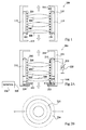
- Figure 2A illustrates the lens barrel 202 positioned at the lowest possible point within the housing 212, and contacting bottom rim 213 of the housing 212. From here, by applying a current to the coil, the lens barrel 202 can move upwards in the housing 212, to a maximum displacement when it is touching the upper rim 214 of the housing 212.
- An electrically conductive ring 222 is fixed to the bottom edge of the lens barrel 202.
- Conductive ring 222 is also connected to spring 218.
- the housing comprises an electrically conductive ring 224 arranged on the upper edge of the bottom rim.
- Conductive rings 222 and 224 make electrical contact with each other.
- Conductive ring 224 is connected by a conductor 225 to a sensing device 226 for detecting a voltage.
- Conductive ring 224 will receive the supply voltage Vdd applied to spring 218 when the lens barrel is in the position in contact with the bottom of the housing as shown in Figure 2A .
- the voltage on conductive ring 224 is used to indicate when the current in the coil 210 is sufficiently high to displace the lens barrel 202.
- FIG. 5 is a graph showing examples of the displacement of the lens barrel 202 with the respect to the current flowing in the coil.
- a typical curve S is shown in the centre.
- a current of 30 mA is needed to start the displacement of the lens barrel, and the lens barrel reaches its maximum displacement, for example equal to 300 ⁇ m, when approximately 53 mA of current is applied.
- the displacement could start at a lower current, for example of 10 mA, as represented by the curve maximum A, or for at a higher current, for example 50 mA, as represented by the curve minimum B.
- the displacement could follow any intermediate curve between the curves A and B, depending on factors such as gravity, friction etc.
- the inventor has found that, in all cases, the curves are substantially straight with substantially equal gradients, and thus by knowing the starting current, the current needed for all positions on the curve can be calculated.
- the circuitry in Figure 2A allows the current level at which movement of the lens barrel starts to be determined.
- the connection between conductive rings 222 and 224 is broken, and this can be detected by detector 226.
- the current is preferably increased in a ramp until movement of the lens barrel is detected, and the current level that has been reached is stored.
- Figure 2B illustrates in plan view conductive ring 222, delimited by solid circles, and conductive ring 224 delimited by dashed circles.
- the conductive rings are annular in shape, and overlap so that an annular region contacts between the two rings when the lens barrel 202 is at the bottom of the housing 212.
- the forces exerted by springs 216 and 218 are generally very low, for example in the region of 10 mN.
- a contact area having a relatively small area can be chosen so give greater pressure between the conductive rings.
- a contact region which is annular in shape is preferable, to ensure that when the two conductive rings contact the lens barrel is not titled within the housing.
- other contact surfaces are possible, preferably providing at least three contact points evenly distributed such that the lens barrel rests without being titled.
- the voltage detector 226 performs a filtering function to filter out bouncing of the contacts that may be present. Additionally, control of the coil is preferably performed such that bouncing is minimized.
- Figure 3A illustrates an alternative embodiment of a mobile lens unit 300 comprising many common features with the embodiment of Figure 2A , and these have been given like reference numerals in Figure 3A and will not be described again in detail.
- the lens barrel 202 further comprises a second conductive ring 326 formed at the top of the lens barrel, and coupled to ring 222 via a conducting track 328, running up the side of the lens barrel.
- the housing 212 further comprises a conductive ring 332 formed on the underside of rim 214 at the top of the housing 212.
- conductive rings 222 and 326 connected to the lens barrel 302 comprise conductive spikes 330, which are designed to make contact with the conductive rings 224 and 332 on the housing 212. By providing spikes 330, more pressure can be applied, and a better contact can be made.
- both conductive rings 224 and 332 of the housing 312 are connected to voltage detectors, ring 224 to the detector 226 via a conductor 225, and ring 332 to a detector 326 through a conductor 325, for detecting when the voltage of the variable voltage source 220 is present.
- a voltage will be present at conductive ring 332 when the lens barrel 302 is at its furthest displacement, and contacts with the upper rim 214 of the housing 212.
- the embodiment of Figure 3A allows not only the initial start current to be determined, but also allows the current that brings the lens barrel to its maximum displacement at the top of the housing 212 to be determined.
- the voltage detector connected to ring 224 determines when a voltage ceases to be present
- the voltage detector connected to ring 332 preferably detects when a voltage is present at ring 332. It will be apparent to those skilled in the art that in alternative embodiments, one can determine at either ring when contact is made or broken. These changes indicate that the lens barrel is either arriving or departing, and in either case this moment corresponds to an end of the straight portions of the curves in Figure 5 .
- the lens barrel can be moved from the bottom of the housing to the top of the housing, such that the start current to move the lens barrel and the current of a maximum displacement of the lens barrel are known. From these two values, and by knowing the distance between the top and bottom of the housing, the gradient of the curve in Figure 5 can be determined, and used to give value R I/S in formula (1) above. In particular, the lens displacement per Amp of current can be determined. This then allows the correct current to be immediately applied to the coil 210 to obtain a desired lens position, by calculating the required current as explained above with reference to formula (1).
- the same operation can be repeated, for example at predetermined time intervals, in case the orientation of the lens barrel with respect to gravity changes.
- contact between the spikes 330 and the conductive rings 324 and 332 can be improved by slamming the lens barrel against the bottom and upper rims of the housing 312, causing a greater force between the spikes 330 and the respective rings 224, 332.
- Figure 3B illustrates, in plan view, the conductive rings 222 and 326 delimited by solid circles and conductive rings 224 and 332 delimited by dashed circles. As illustrated, both of these rings are circular in this embodiment, and in this embodiment four spikes 330 are provided at even spaces around the rings. Preferably at least three spikes are provided, or a greater number of spikes could be provided.
- Figure 4 illustrates schematically components of a device 400.
- Device 400 is for example a digital camera, mobile telephone, PDA (personal digital assistant), endoscope or the like.
- Device 400 comprises a microprocessor 402, lens unit 404, image sensor 406, memory 408, auto-focus block 410 and other devices 412, which are for example a display for displaying images, an input device such as a keypad, and/or alternative devices.
- Line 413 is provided from the microprocessor to the lens unit
- lines 416 and 418 are provided from the auto-focus block 410 to and from the image sensor 406, and lines 422 and 424 are provided from the microprocessor 402 to and from the auto-focus block 410.
- Lines 426 and 428 are provided from the auto-focus block 410 to and from the memory block 408.
- the lens unit 404 may correspond to one of the embodiments shown in Figures 2A or 3A .
- the microprocessor 402 provides a signal on line 413 to the lens unit 404 indicating the current to be applied to the coil of the lens barrel, to cause its displacement. It receives, on line 225 from the lens unit 404, the signal from ring 224, and in the case of Figure 3A also the signal 325 from ring 332.
- the microprocessor 402 is able to control the lens barrel of the lens unit and determine the current values required for starting the movement of the lens barrel, and/or for generating the maximum displacement of the lens barrel. From these values, the microprocessor 402 can calculate the required current to provide a signal to the lens unit for a given positioning of the fixed lenses, for example using formula (1) above.
- the image sensor 406 receives an image from the lens unit 404 and transforms it to an electrical representation 420 that is sent to an auto-focus block 410.
- the auto-focus block 410 determines the required focusing of the image. It could be the baseband processor of a mobile telephone, image processor or a dedicated auto-focus processor. Auto-focus block 410 for example stores this image in memory 408 and/or displays it on a display. In some embodiments, the auto-focus block also determines the sharpness of the image, and generates a focus control signal on line 422 to the microprocessor 402 based on this signal. To react to different environments the auto-block 410 may control the image sensor 406 through line 416.
- the auto-focus block 410 commands microprocessor 402 to move the lens barrel of the lens unit 404 to a specified position based on factors such as the determined focusing of the image or the mode of operation, for example in the case that a macro or landscape mode has been selected by a user.
- the microprocessor 402 performs necessary control of the lens unit 404 including above described methods for detecting the lens movement and for example provides status information to the auto-focus block 410 via line 424.
- microprocessor 402 has been illustrated as a separate entity, it could be incorporated in the auto-focus block 410 or in the image sensor 406, for example to save space.
- the current required to initially displace the lens barrel can be determined, with minimal circuitry. All that will be required is a detector for example provided by a microprocessor, to detect, from the voltage level, when the lens barrel is no longer in contact with the housing.
- the particular circuitry required to perform these functions will be within the capabilities of one skilled in the art.
- the conductors are preferably made of materials that make good electrical contact when only a low force is applied between them, such as copper, or a material coated with a gold, platinum, palladium or similar alloy plating.
- the current required to provide a maximum displacement of the lens barrel could be determined, and this could then be used to calculate the current required to displace the lens to the given position.
- the upper point of the curve instead of determining the bottom point of the current/displacement curve, the upper point of the curve alone could be determined.
- VCM variable current source
- VCM variable voltage source
- spikes 330 have been provided on the rings 322 and 326 attached to the lens barrel, in alternative embodiments no spikes could be provided here, and instead spikes could be provided on the rings 224 and 332 attached to the housing 312.
Landscapes
- Physics & Mathematics (AREA)
- General Physics & Mathematics (AREA)
- Engineering & Computer Science (AREA)
- Chemical & Material Sciences (AREA)
- Combustion & Propulsion (AREA)
- Electromagnetism (AREA)
- Power Engineering (AREA)
- Optics & Photonics (AREA)
- Lens Barrels (AREA)
Applications Claiming Priority (1)
| Application Number | Priority Date | Filing Date | Title |
|---|---|---|---|
| FR0755412 | 2007-06-01 |
Publications (2)
| Publication Number | Publication Date |
|---|---|
| EP1998202A1 true EP1998202A1 (fr) | 2008-12-03 |
| EP1998202B1 EP1998202B1 (fr) | 2013-12-18 |
Family
ID=38611086
Family Applications (1)
| Application Number | Title | Priority Date | Filing Date |
|---|---|---|---|
| EP08157268.7A Active EP1998202B1 (fr) | 2007-06-01 | 2008-05-30 | Unité de lentille mobile avec dispositif de détection |
Country Status (2)
| Country | Link |
|---|---|
| US (1) | US7679849B2 (fr) |
| EP (1) | EP1998202B1 (fr) |
Cited By (1)
| Publication number | Priority date | Publication date | Assignee | Title |
|---|---|---|---|---|
| CN112305729A (zh) * | 2019-08-02 | 2021-02-02 | Oppo广东移动通信有限公司 | 变焦镜头、相机模组和电子装置 |
Families Citing this family (26)
| Publication number | Priority date | Publication date | Assignee | Title |
|---|---|---|---|---|
| US8068899B2 (en) | 2007-07-03 | 2011-11-29 | The Board Of Trustees Of The Leland Stanford Junior University | Method and system of using intrinsic-based photosensing with high-speed line scanning for characterization of biological thick tissue including muscle |
| JP4457320B2 (ja) * | 2008-03-05 | 2010-04-28 | ソニー株式会社 | カメラモジュール |
| DE102008026774B4 (de) * | 2008-06-04 | 2018-09-20 | Carl Zeiss Microscopy Gmbh | Steuerungseinrichtung für Stellglieder in Mikroskopobjektiven |
| DE102008042356A1 (de) | 2008-09-25 | 2010-04-08 | Carl Zeiss Smt Ag | Projektionsbelichtungsanlage mit optimierter Justagemöglichkeit |
| KR101571333B1 (ko) * | 2009-01-22 | 2015-11-24 | 삼성전자주식회사 | 디지털 영상 처리 장치 |
| JP5158720B2 (ja) * | 2009-03-11 | 2013-03-06 | 富士フイルム株式会社 | 光学モジュールおよびその製造方法、並びに撮像装置 |
| EP2785250A4 (fr) * | 2011-11-28 | 2015-07-29 | Univ Leland Stanford Junior | Système et procédé utiles pour imagerie de sarcomère par l'intermédiaire de microscopie basée sur objectif |
| US20130169832A1 (en) * | 2011-12-29 | 2013-07-04 | Lg Innotek Co., Ltd. | Camera module and auto focusing method of camera module |
| EP3385767B1 (fr) | 2012-05-09 | 2020-06-24 | Lg Innotek Co. Ltd | Moteur à bobine mobile |
| CN105611865B (zh) * | 2013-12-18 | 2018-06-19 | 奥林巴斯株式会社 | 内窥镜系统 |
| WO2015111884A1 (fr) * | 2014-01-22 | 2015-07-30 | Lg Electronics Inc. | Module d'appareil photo et son procédé de mise au point automatique |
| US9395511B1 (en) | 2014-01-30 | 2016-07-19 | Magnet-Schultz Of America, Inc. | Voice coil actuator with integrated LVDT |
| US10224742B2 (en) | 2015-01-18 | 2019-03-05 | Powerpath Technologies Incorporated | High efficiency uninterruptible power supply with near loss-less ultrafast electromechanical switching |
| JP6677454B2 (ja) * | 2015-05-07 | 2020-04-08 | 株式会社アールエフ | 撮像装置および口腔内カメラ |
| CN115919266A (zh) | 2016-03-08 | 2023-04-07 | 恩斯派克特拉健康公司 | 皮肤疾病的非侵入式检测 |
| CN108781256B (zh) | 2016-03-09 | 2020-08-11 | Lg 电子株式会社 | 控制相机模块的自动聚焦的装置和方法 |
| KR20170126760A (ko) | 2016-05-10 | 2017-11-20 | 엘지전자 주식회사 | 카메라 모듈 및 그의 오토 포커스 방법 |
| US9888164B1 (en) * | 2016-08-05 | 2018-02-06 | Microsoft Technology Licensing, Llc | Digital camera focus self-calibration |
| EP3614915A4 (fr) | 2017-04-28 | 2021-01-20 | Enspectra Health, Inc. | Systèmes et méthodes d'imagerie et de mesure de sarcomes |
| JP7123137B2 (ja) * | 2017-11-22 | 2022-08-22 | オプトチューン コンシューマー アーゲー | オートフォーカス及び光学式手ぶれ補正機構を備える光学デバイス、特にカメラ |
| JP2019095662A (ja) * | 2017-11-24 | 2019-06-20 | 株式会社ブイ・テクノロジー | 光学装置の取付構造及び露光装置 |
| JP2021156906A (ja) * | 2018-05-01 | 2021-10-07 | オリンパス株式会社 | 光学ユニット |
| JP7017239B2 (ja) * | 2018-06-25 | 2022-02-08 | 株式会社ブイ・テクノロジー | 露光装置および高さ調整方法 |
| CN113473900B (zh) | 2018-11-13 | 2024-09-24 | 恩斯派克特拉健康公司 | 用于生成深度剖面的方法和系统 |
| WO2020166070A1 (fr) * | 2019-02-15 | 2020-08-20 | オリンパス株式会社 | Endoscope, procédé de mise à la terre et procédé de mise à la terre d'une section d'extrémité de pointe d'un endoscope |
| CN110764273B (zh) * | 2019-10-31 | 2022-08-19 | 京东方科技集团股份有限公司 | 透镜模块、显示装置及显示方法 |
Citations (7)
| Publication number | Priority date | Publication date | Assignee | Title |
|---|---|---|---|---|
| EP0459889A1 (fr) * | 1990-05-28 | 1991-12-04 | Sony Corporation | Actionneur du type à bobine mobile |
| US5111230A (en) * | 1989-08-29 | 1992-05-05 | Copal Company Limited | Lens shutter driving mechanism using lens driving mechanism |
| EP0485302A2 (fr) * | 1990-11-09 | 1992-05-13 | Sony Corporation | Tube de lentille pour caméra |
| EP0694799A2 (fr) * | 1994-07-26 | 1996-01-31 | Canon Kabushiki Kaisha | Appareil optique |
| US20060061442A1 (en) * | 2004-05-20 | 2006-03-23 | Elliot Brooks | Eddy current inductive drive electromechanical linear actuator and switching arrangement |
| US20070047942A1 (en) * | 2005-08-25 | 2007-03-01 | Powergate Optical Inc. | Auto-focusing device with voice coil motor for position feedback and method for using same |
| US20070046109A1 (en) * | 2005-08-25 | 2007-03-01 | Powergate Optical Inc. | Miniature linear motor driving device and auto-focus lens device using the same |
Family Cites Families (9)
| Publication number | Priority date | Publication date | Assignee | Title |
|---|---|---|---|---|
| US2782683A (en) * | 1954-02-18 | 1957-02-26 | Joseph B Walker | Selective electrical lens adjusting machanisms for variable magnification systems |
| DE2627254C3 (de) * | 1976-06-18 | 1981-08-13 | Bodenseewerk Perkin-Elmer & Co GmbH, 7770 Überlingen | Verfahren zur Messung oder Regelung der Temperatur eines Graphitrohres |
| JPS63298232A (ja) * | 1987-05-29 | 1988-12-06 | Fuji Photo Optical Co Ltd | 多焦点カメラ |
| US4867574A (en) * | 1988-05-19 | 1989-09-19 | Jenkofsky John J | Ultra high speed infrared temperature measuring device |
| JPH03198320A (ja) * | 1989-12-27 | 1991-08-29 | Nikon Corp | 投影光学装置 |
| US5383060A (en) * | 1992-11-20 | 1995-01-17 | Litton Systems, Inc. | Dynamic compensating laser telescope apparatus |
| US6954292B2 (en) * | 2000-09-13 | 2005-10-11 | Fuji Photo Film Co., Ltd. | Image scan apparatus and focus control method |
| DE10159239A1 (de) * | 2001-12-03 | 2003-06-26 | Leica Microsystems | Mikroskopobjektiv, Mikroskop und Verfahren zum Abbilden einer Probe |
| US7408728B2 (en) * | 2006-12-04 | 2008-08-05 | Quality Vision International, Inc. | System and method for focal length stabilization using active temperature control |
-
2008
- 2008-05-30 US US12/129,703 patent/US7679849B2/en active Active
- 2008-05-30 EP EP08157268.7A patent/EP1998202B1/fr active Active
Patent Citations (7)
| Publication number | Priority date | Publication date | Assignee | Title |
|---|---|---|---|---|
| US5111230A (en) * | 1989-08-29 | 1992-05-05 | Copal Company Limited | Lens shutter driving mechanism using lens driving mechanism |
| EP0459889A1 (fr) * | 1990-05-28 | 1991-12-04 | Sony Corporation | Actionneur du type à bobine mobile |
| EP0485302A2 (fr) * | 1990-11-09 | 1992-05-13 | Sony Corporation | Tube de lentille pour caméra |
| EP0694799A2 (fr) * | 1994-07-26 | 1996-01-31 | Canon Kabushiki Kaisha | Appareil optique |
| US20060061442A1 (en) * | 2004-05-20 | 2006-03-23 | Elliot Brooks | Eddy current inductive drive electromechanical linear actuator and switching arrangement |
| US20070047942A1 (en) * | 2005-08-25 | 2007-03-01 | Powergate Optical Inc. | Auto-focusing device with voice coil motor for position feedback and method for using same |
| US20070046109A1 (en) * | 2005-08-25 | 2007-03-01 | Powergate Optical Inc. | Miniature linear motor driving device and auto-focus lens device using the same |
Cited By (1)
| Publication number | Priority date | Publication date | Assignee | Title |
|---|---|---|---|---|
| CN112305729A (zh) * | 2019-08-02 | 2021-02-02 | Oppo广东移动通信有限公司 | 变焦镜头、相机模组和电子装置 |
Also Published As
| Publication number | Publication date |
|---|---|
| US7679849B2 (en) | 2010-03-16 |
| EP1998202B1 (fr) | 2013-12-18 |
| US20080297922A1 (en) | 2008-12-04 |
Similar Documents
| Publication | Publication Date | Title |
|---|---|---|
| EP1998202B1 (fr) | Unité de lentille mobile avec dispositif de détection | |
| CN111433649B (zh) | 光学变焦装置 | |
| US7352389B2 (en) | Anti-shake apparatus for correcting hand shake effect through first and second drive coil units | |
| US20110002681A1 (en) | Imaging apparatus | |
| CN111856840B (zh) | 镜头驱动装置、相机模块和光学设备 | |
| KR101068528B1 (ko) | 카메라모듈 및 그 제어방법 | |
| US20160105612A1 (en) | Blur correction apparatus | |
| CN107092069A (zh) | 透镜驱动装置、照相装置与电子设备 | |
| KR20200007252A (ko) | 자동 초점 조절장치 | |
| WO2013098595A1 (fr) | Module d'appareil photo, dispositif électronique le contenant et procédé de mise au point automatique | |
| JP2009058601A (ja) | レンズ駆動装置及び撮像装置並びに携帯端末 | |
| CN101266387A (zh) | 小型摄像头模块位移感知传感器 | |
| CN101971071A (zh) | 摄像装置 | |
| EP1598687A3 (fr) | Dispositif de commande d'entrainement pour dispositif à lentille | |
| US10900810B2 (en) | Electronic equipment that determines rotation direction and rotating amount of rotational operation member | |
| US8180211B2 (en) | Drop detection using lens position sensing of camera module | |
| CN111025521B (zh) | 自动对焦滚珠式usm的透镜驱动装置、相机装置及电子设备 | |
| CN110873938B (zh) | 镜头设备和具有该镜头设备的照相机系统 | |
| JP2015114615A (ja) | 撮影用光学装置および撮影用光学装置の制御方法 | |
| KR102327732B1 (ko) | 액추에이터 구동 장치 및 이를 포함하는 카메라 모듈 | |
| US12235568B2 (en) | Linkage apparatus, camera module, and electronic device | |
| WO2025054932A1 (fr) | Actionneur pour caméra, module de caméra et appareil d'imagerie | |
| KR101865206B1 (ko) | 자동 초점용 액츄에이터 | |
| JP2008129111A (ja) | レンズ駆動装置及びレンズ駆動方法 | |
| CN101266388A (zh) | 微型摄像头模块位移传感器 |
Legal Events
| Date | Code | Title | Description |
|---|---|---|---|
| PUAI | Public reference made under article 153(3) epc to a published international application that has entered the european phase |
Free format text: ORIGINAL CODE: 0009012 |
|
| AK | Designated contracting states |
Kind code of ref document: A1 Designated state(s): AT BE BG CH CY CZ DE DK EE ES FI FR GB GR HR HU IE IS IT LI LT LU LV MC MT NL NO PL PT RO SE SI SK TR |
|
| AX | Request for extension of the european patent |
Extension state: AL BA MK RS |
|
| 17P | Request for examination filed |
Effective date: 20090602 |
|
| 17Q | First examination report despatched |
Effective date: 20090625 |
|
| AKX | Designation fees paid |
Designated state(s): DE FR GB IT |
|
| REG | Reference to a national code |
Ref country code: DE Ref legal event code: R079 Ref document number: 602008029359 Country of ref document: DE Free format text: PREVIOUS MAIN CLASS: G02B0007040000 Ipc: G03B0003100000 |
|
| RIC1 | Information provided on ipc code assigned before grant |
Ipc: H02K 41/035 20060101ALI20121120BHEP Ipc: G03B 13/36 20060101ALI20121120BHEP Ipc: G03B 3/10 20060101AFI20121120BHEP Ipc: G02B 7/08 20060101ALI20121120BHEP |
|
| GRAP | Despatch of communication of intention to grant a patent |
Free format text: ORIGINAL CODE: EPIDOSNIGR1 |
|
| INTG | Intention to grant announced |
Effective date: 20130710 |
|
| GRAS | Grant fee paid |
Free format text: ORIGINAL CODE: EPIDOSNIGR3 |
|
| GRAA | (expected) grant |
Free format text: ORIGINAL CODE: 0009210 |
|
| AK | Designated contracting states |
Kind code of ref document: B1 Designated state(s): DE FR GB IT |
|
| REG | Reference to a national code |
Ref country code: GB Ref legal event code: FG4D |
|
| REG | Reference to a national code |
Ref country code: DE Ref legal event code: R096 Ref document number: 602008029359 Country of ref document: DE Effective date: 20140213 |
|
| REG | Reference to a national code |
Ref country code: DE Ref legal event code: R097 Ref document number: 602008029359 Country of ref document: DE |
|
| PLBE | No opposition filed within time limit |
Free format text: ORIGINAL CODE: 0009261 |
|
| STAA | Information on the status of an ep patent application or granted ep patent |
Free format text: STATUS: NO OPPOSITION FILED WITHIN TIME LIMIT |
|
| 26N | No opposition filed |
Effective date: 20140919 |
|
| REG | Reference to a national code |
Ref country code: DE Ref legal event code: R097 Ref document number: 602008029359 Country of ref document: DE Effective date: 20140919 |
|
| GBPC | Gb: european patent ceased through non-payment of renewal fee |
Effective date: 20140530 |
|
| REG | Reference to a national code |
Ref country code: FR Ref legal event code: ST Effective date: 20150130 |
|
| PG25 | Lapsed in a contracting state [announced via postgrant information from national office to epo] |
Ref country code: GB Free format text: LAPSE BECAUSE OF NON-PAYMENT OF DUE FEES Effective date: 20140530 Ref country code: FR Free format text: LAPSE BECAUSE OF NON-PAYMENT OF DUE FEES Effective date: 20140602 |
|
| PG25 | Lapsed in a contracting state [announced via postgrant information from national office to epo] |
Ref country code: IT Free format text: LAPSE BECAUSE OF FAILURE TO SUBMIT A TRANSLATION OF THE DESCRIPTION OR TO PAY THE FEE WITHIN THE PRESCRIBED TIME-LIMIT Effective date: 20131218 |
|
| REG | Reference to a national code |
Ref country code: DE Ref legal event code: R081 Ref document number: 602008029359 Country of ref document: DE Owner name: STMICROELECTRONICS (GRENOBLE 2) SAS, FR Free format text: FORMER OWNER: STMICROELECTRONICS (GRENOBLE) SAS, GRENOBLE, FR |
|
| PGFP | Annual fee paid to national office [announced via postgrant information from national office to epo] |
Ref country code: DE Payment date: 20250423 Year of fee payment: 18 |