EP1998231A1 - Dispositif de développement et appareil de formation d'images l'incluant - Google Patents
Dispositif de développement et appareil de formation d'images l'incluant Download PDFInfo
- Publication number
- EP1998231A1 EP1998231A1 EP08156979A EP08156979A EP1998231A1 EP 1998231 A1 EP1998231 A1 EP 1998231A1 EP 08156979 A EP08156979 A EP 08156979A EP 08156979 A EP08156979 A EP 08156979A EP 1998231 A1 EP1998231 A1 EP 1998231A1
- Authority
- EP
- European Patent Office
- Prior art keywords
- developer
- container
- developing device
- toner
- agitation
- Prior art date
- Legal status (The legal status is an assumption and is not a legal conclusion. Google has not performed a legal analysis and makes no representation as to the accuracy of the status listed.)
- Withdrawn
Links
- 238000013019 agitation Methods 0.000 claims abstract description 89
- 238000011144 upstream manufacturing Methods 0.000 claims abstract description 3
- 238000003756 stirring Methods 0.000 claims description 18
- 230000001678 irradiating effect Effects 0.000 claims description 5
- 230000005484 gravity Effects 0.000 claims description 2
- 238000000034 method Methods 0.000 description 7
- 230000008859 change Effects 0.000 description 4
- 238000004140 cleaning Methods 0.000 description 4
- 230000015572 biosynthetic process Effects 0.000 description 3
- 239000000470 constituent Substances 0.000 description 3
- 230000003247 decreasing effect Effects 0.000 description 2
- 230000007246 mechanism Effects 0.000 description 2
- 230000037361 pathway Effects 0.000 description 2
- 230000002093 peripheral effect Effects 0.000 description 2
- 230000008569 process Effects 0.000 description 2
- 239000003086 colorant Substances 0.000 description 1
- 230000000052 comparative effect Effects 0.000 description 1
- 230000007812 deficiency Effects 0.000 description 1
- 230000000593 degrading effect Effects 0.000 description 1
- 230000006866 deterioration Effects 0.000 description 1
- 230000007613 environmental effect Effects 0.000 description 1
- 239000000463 material Substances 0.000 description 1
- 230000004048 modification Effects 0.000 description 1
- 238000012986 modification Methods 0.000 description 1
- 230000003472 neutralizing effect Effects 0.000 description 1
- 230000003287 optical effect Effects 0.000 description 1
- 239000002245 particle Substances 0.000 description 1
- 230000009467 reduction Effects 0.000 description 1
- 230000004044 response Effects 0.000 description 1
Images


Classifications
-
- G—PHYSICS
- G03—PHOTOGRAPHY; CINEMATOGRAPHY; ANALOGOUS TECHNIQUES USING WAVES OTHER THAN OPTICAL WAVES; ELECTROGRAPHY; HOLOGRAPHY
- G03G—ELECTROGRAPHY; ELECTROPHOTOGRAPHY; MAGNETOGRAPHY
- G03G15/00—Apparatus for electrographic processes using a charge pattern
- G03G15/06—Apparatus for electrographic processes using a charge pattern for developing
- G03G15/08—Apparatus for electrographic processes using a charge pattern for developing using a solid developer, e.g. powder developer
- G03G15/0822—Arrangements for preparing, mixing, supplying or dispensing developer
- G03G15/0877—Arrangements for metering and dispensing developer from a developer cartridge into the development unit
-
- G—PHYSICS
- G03—PHOTOGRAPHY; CINEMATOGRAPHY; ANALOGOUS TECHNIQUES USING WAVES OTHER THAN OPTICAL WAVES; ELECTROGRAPHY; HOLOGRAPHY
- G03G—ELECTROGRAPHY; ELECTROPHOTOGRAPHY; MAGNETOGRAPHY
- G03G15/00—Apparatus for electrographic processes using a charge pattern
- G03G15/06—Apparatus for electrographic processes using a charge pattern for developing
- G03G15/08—Apparatus for electrographic processes using a charge pattern for developing using a solid developer, e.g. powder developer
- G03G15/0822—Arrangements for preparing, mixing, supplying or dispensing developer
- G03G15/0848—Arrangements for testing or measuring developer properties or quality, e.g. charge, size, flowability
- G03G15/0849—Detection or control means for the developer concentration
-
- G—PHYSICS
- G03—PHOTOGRAPHY; CINEMATOGRAPHY; ANALOGOUS TECHNIQUES USING WAVES OTHER THAN OPTICAL WAVES; ELECTROGRAPHY; HOLOGRAPHY
- G03G—ELECTROGRAPHY; ELECTROPHOTOGRAPHY; MAGNETOGRAPHY
- G03G15/00—Apparatus for electrographic processes using a charge pattern
- G03G15/06—Apparatus for electrographic processes using a charge pattern for developing
- G03G15/08—Apparatus for electrographic processes using a charge pattern for developing using a solid developer, e.g. powder developer
- G03G15/0822—Arrangements for preparing, mixing, supplying or dispensing developer
- G03G15/0877—Arrangements for metering and dispensing developer from a developer cartridge into the development unit
- G03G15/0879—Arrangements for metering and dispensing developer from a developer cartridge into the development unit for dispensing developer from a developer cartridge not directly attached to the development unit
-
- G—PHYSICS
- G03—PHOTOGRAPHY; CINEMATOGRAPHY; ANALOGOUS TECHNIQUES USING WAVES OTHER THAN OPTICAL WAVES; ELECTROGRAPHY; HOLOGRAPHY
- G03G—ELECTROGRAPHY; ELECTROPHOTOGRAPHY; MAGNETOGRAPHY
- G03G2215/00—Apparatus for electrophotographic processes
- G03G2215/08—Details of powder developing device not concerning the development directly
- G03G2215/0802—Arrangements for agitating or circulating developer material
- G03G2215/0816—Agitator type
- G03G2215/0819—Agitator type two or more agitators
Definitions
- Exemplary aspects of the present invention generally relate to a developing device employing a stirring mechanism for a two-component developer, and an image forming apparatus including the developing device.
- a related-art image forming apparatus such as a copier, a facsimile machine, a printer, or a multifunction printer having two or more of copying, printing, scanning, and facsimile functions, forms a toner image on a recording medium (e.g., a sheet) according to image data using an electrophotographic method.
- a recording medium e.g., a sheet
- a charger charges a surface of an image bearing member (e.g., a photoconductor); an optical scanning device emits a light beam onto the charged surface of the photoconductor to form an electrostatic latent image on the photoconductor according to the image data; the electrostatic latent image is developed with a developer (e.g., a toner) to form a toner image on the photoconductor; a transfer device transfers the toner image formed on the photoconductor onto a sheet; and a fixing device applies heat and pressure to the sheet bearing the toner image to fix the toner image onto the sheet.
- the sheet bearing the fixed toner image is then discharged from the image forming apparatus.
- a one-component developer consisting essentially of a toner (e.g., magnetic toner and non-magnetic toner) or a two-component developer including a toner and a carrier which carries the toner is used for development.
- a toner e.g., magnetic toner and non-magnetic toner
- a two-component developer including a toner and a carrier which carries the toner
- the toner when agitated and mixed into the carrier, is frictionally charged so as to be electrostatically attracted to the electrostatic latent image formed on the photoconductor. Thus, the toner is consumed during development whereas the carrier is not.
- a typical developing device which holds the developer, generally includes a developing sleeve, configured to form a magnetic brush of the developer on a surface thereof and to supply the developer to the electrostatic latent image formed on the photoconductor, and an agitator sleeve, configured to supply agitated developer to the developing sleeve. Developer in which the toner has been consumed in the development of the electrostatic latent image formed on the photoconductor is collected and returned to the developing device.
- the fresh toner may be supplied from above a conveyance screw including a screw auger serving as the agitator sleeve, or from an edge of a rotation shaft of the conveyance screw.
- the fresh toner is supplied to the developer based on developer density detected by a toner density sensor or the like, in amounts controlled by controlling a rotation of a supply member configured to supply the fresh toner stored in a toner supply unit.
- a supply member configured to supply the fresh toner stored in a toner supply unit.
- JP-A 2001-188408 discloses a developing device including a screw auger configured to agitate a developer to frictionally charge the developer as described above.
- JP-A 11-143196 discloses a developing device in which an agitating unit provided separately from a developing unit at a position where a developer is circulated agitates collected developer and supplied toner so that the resultant developer is frictionally charged.
- JP 3734096 discloses a developing device in which an agitating unit provided separately from a developing unit includes a screw auger configured to move a developer upward.
- the supplied toner is dispersed throughout the developer, and the developer is frictionally charged by being agitated by rotation of the screw auger for a short time until the developer thus prepared is conveyed to the developing sleeve. Consequently, the degree of mixing depends in part on the amounts supplied. Thus, when a larger amount of toner is supplied to the developer, the toner may not be dispersed sufficiently in the developer in the brief time allotted for agitation, and consequently, the toner may not be charged sufficiently when discharged from the developer tank. As a result, weakly charged toner could reach the developing sleeve, fouling of a surface of the photoconductor and scattering over peripheral components, thereby degrading image quality.
- One possible method for solving the above-described problem is to increase a rotation speed of the screw auger to cause the toner to contact the carrier more frequently so that a predetermined or desired charge is reliably applied to the developer.
- the screw auger driving system may be damaged due to the increased transfer resistance to the developer when the developer is agitated.
- the toner may be damaged due to increased force of impact on the developer and heat caused by increased friction, increasing stress on the developer.
- exemplary embodiments of the present invention provide a developing device using a two-component developer, in which a mechanism capable of supplying a necessary amount of the developer having a predetermined or desired toner density and charge without causing deterioration of the developer is included, and an image forming apparatus employing the developing device.
- a developing device includes a developing unit configured to develop an electrostatic latent image formed on a latent image bearing member with a developer comprising a toner and a carrier, and a circulation unit configured to collect the developer from the developing unit and return the developer to the developing unit.
- the circulation unit includes a container including a main body having an inverted cone shape, a supply opening provided in a top thereof, and a discharge opening provided in a bottom thereof, configured to hold a part of the developer and provided on an upstream side from the developing unit relative to a direction of circulation of the developer.
- the container includes a plurality of agitation members configured to agitate the developer collected from the developing unit and fresh toner so that a plurality of flows of the developer is produced in the container.
- an image forming apparatus including a latent image bearing member configured to bear an electrostatic latent image; a charging device configured to charge a surface of the latent image bearing member; an irradiating device configured to scan and irradiate a charged surface of the latent image bearing member with a light beam according to image data to form an electrostatic latent image thereon; a developing device configured to develop the electrostatic latent image with a toner to form a toner image, which includes the developing unit and the circulation unit as described above; a transfer device configured to transfer the toner image onto a recording medium; and a fixing device configured to fix the toner image on the recording medium.
- paper is the medium from which is made a sheet on which an image is to be formed. It should be noted, however, that other printable media are available in sheets, and accordingly their use here is included. Thus, solely for simplicity, although this Detailed Description section refers to paper, sheets thereof, paper feeder, etc., it should be understood that the sheets, etc., are not limited only to paper but includes other printable media as well.
- FIG. 1 is a schematic view illustrating an embodiment of an image forming apparatus 100 employing a developing device according to exemplary embodiments.
- image forming units 6Y, 6M, 6C, and 6Bk (hereinafter collectively referred to as image forming units 6), respectively corresponding to toner colors of yellow, magenta, cyan, and black, are arranged side by side facing a lower surface of an intermediate transfer belt 8 serving as an unfixed image bearing member of an intermediate transfer unit 10.
- image forming units 6 has the same configuration, the only difference being the color of the toner used for image formation.
- the image forming units 6Y, 6M, 6C, and 6Bk respectively, include photoconductive drums 1Y, 1M, 1C, and 1Bk (hereinafter collectively referred to as photoconductive drums 1), each serving as a latent image bearing member; chargers, not shown, respectively provided around the photoconductive drums 1; developing devices 5Y, 5M, 5C, and 5Bk. (hereinafter collectively referred to as developing devices 5); cleaning devices, not shown; and so forth.
- Image formation including charging, irradiating, developing, transferring, and cleaning, is performed on each of the photoconductive drums 1. As a result, respective toner images are formed on the photoconductive drums 1.
- the photoconductive drums 1 are rotatively driven in a clockwise direction in FIG. 1 by a driving unit, not shown. Surfaces of the photoconductive drums 1 are evenly charged by the chargers.
- the laser beams are respectively scanned across the surfaces of the photoconductive drums 1 so that electrostatic latent images are respectively formed on the surfaces of the photoconductive drums 1.
- the electrostatic latent images thus formed on the surfaces of the photoconductive drums 1 respectively reach the developing units 5, the electrostatic latent images are formed into visible images by toners included in developers supplied from the developing units 5.
- the surfaces of the photoconductive drums 1 respectively reach the cleaning devices. Toner particles remaining on the surfaces of the photoconductive drums 1 are removed by the cleaning devices. Thereafter, charges on the surfaces of the photoconductive drums 1 are respectively neutralized by neutralizing rollers, not shown, thus completing one complete set of image forming operations performed on the photoconductive drums 1.
- the image formation described above is performed in each of the image forming units 6. Specifically, based on image data, laser beams are respectively emitted from the irradiating units provided below the image forming units 6 and directed onto the surfaces of the photoconductive drums 1. Thereafter, the respective color toner images formed on the surfaces of the photoconductive drums 1 through development are primarily transferred onto the intermediate transfer belt 8 in a primary transfer process so that the toner images are superimposed on one another on the intermediate transfer belt 8. Accordingly, a color toner image is formed on the intermediate transfer belt 8.
- the primary transfer bias rollers 9Y, 9M, 9C, and 9Bk (hereinafter collectively referred to as primary transfer bias rollers 9) respectively form primary transfer nips with the photoconductive drums 1Y, 1M, 1C, and 1Bk with the intermediate transfer belt 8 therebetween.
- a transfer bias having a polarity opposite to that of the toner is applied to each of the primary transfer bias rollers 9.
- the intermediate transfer belt 8 is rotated in a direction indicated by an arrow G in FIG. 1 , and sequentially passes through the primary transfer nips respectively formed by the primary transfer bias rollers 9. As a result, the toner images respectively formed on the photoconductive drums 1 are primarily transferred onto the intermediate transfer belt 8, and the color toner image is formed on the intermediate transfer belt 8.
- the color toner image formed on the intermediate transfer belt 8 reaches a secondary transfer roller 19 serving as a secondary transfer means, the color toner image is transferred onto a transfer sheet P serving as a recording medium conveyed to a secondary transfer nip.
- a paper feeder 26 provided on the bottom of the image forming apparatus 100 stores a plurality of transfer sheets P.
- the transfer sheets P are fed sheet by sheet by a paper feed roller 27.
- the transfer sheet P thus fed is temporality stopped by a pair of registration rollers 28.
- the transfer sheet P is conveyed to the secondary'transfer nip at a predetermined or desired timing by the pair of registration rollers 28. Accordingly, the color toner image is transferred onto the transfer sheet P at the secondary transfer nip as described above.
- the transfer sheet P having the color toner image thereon is conveyed to a fixing device 20.
- a fixing device 20 heat and pressure are applied to the transfer sheet P from a fixing roller and a pressure roller to fix the color'toner image onto the transfer sheet P.
- the transfer sheet P having a fixed image thereon is discharged by a pair of discharge rollers 29 and stacked on a discharge tray 30 provided on an upper surface of the image forming apparatus 100.
- a pair of discharge rollers 29 and stacked on a discharge tray 30 provided on an upper surface of the image forming apparatus 100 are discharged by a pair of discharge rollers 29 and stacked on a discharge tray 30 provided on an upper surface of the image forming apparatus 100.
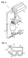
- FIG. 2 is a perspective view illustrating an example of a configuration of the developing device 5 according to exemplary embodiments.
- the developing device 5 includes a developing unit 50 configured to develop electrostatic latent images on the photoconductive drums 1 with a two-component developer comprising a carrier and a toner, and a circulation unit configured to convey a developer collected from the developing unit 50 to a developer supply unit of the developing unit 50.
- the developing device 5 includes the developing unit 50; a developer container 51 configured to agitate the developer collected from the developing unit 50 and fresh toner of the same amount as that of toner consumed in the developing unit 50, provided separately from the developing unit 50; a toner cartridge 52 configured to supply fresh toner to the developer container 51; an air pump 54 serving as a developer circulation driving source for conveying the developer to the developing unit 50 with pressure; and so forth.
- the developing unit 50 is a cartridge type.
- the developing unit 50 and the developer container 51 are connected by a circulation path 56 included in the circulation unit.
- the circulation path 56 includes an onward portion configured to convey the developer collected from the developing unit 50 to the developer container 51; and a return portion configured to convey the developer discharged from the developer container 51 to the developing unit 50, connected to one of conveyance screws each serving as the developer supply unit of the developing unit 50.
- reference numeral 59 denotes a motor serving as a toner supply driving source
- reference numeral 60 denotes a motor serving as an agitation driving source.
- FIG. 3 is a schematic view illustrating an internal configuration of the developing unit 50.
- the developing unit 50 includes a casing 62; conveyance screws 63 and 64 each having a spiral fin, rotatively supported in the casing 62; and a developing roller 65.
- the casing 62 is filled with the two-component developer comprising a toner and a carrier.
- the two-component developer is circulated and conveyed in the casing 62 by the conveyance screws 63 and 64.
- the developer is conveyed by the conveyance screw 63 from a front side to a back side relative to the plane of paper on which FIG. 3 is illustrated, and a part of the developer thus conveyed is attracted to the developing roller 65 by magnetic force. Thereafter, a doctor blade 66 equalizes a thickness of the developer on the developing roller 65.
- the developing roller 65 contacts the photoconductive drum 1, the electrostatic latent image formed on the photoconductive drum 1 is developed with the toner. Accordingly, a toner image is formed on the photoconductive drum 1.
- the developer After development, the developer is conveyed from a discharge opening 67 shown in FIG. 2 , provided on an edge of the conveyance screw 64, to the developer container 51. through the onward portion of the circulation path 56.
- a toner density detector is provided on an extreme downstream portion of the conveyance screw 64. Fresh toner is supplied from the toner cartridge 52 in response to a signal from the toner density detector.
- the fresh toner is supplied from the toner cartridge 52 to the developer container 51 by rotating a screw, not shown, provided in a toner supply path 57 by a motor 59.
- the fresh toner is supplied to the developer while being conveyed to the developer container 51 at a portion immediately above an entry to the developer container 51.
- the developer collected from the developing unit 50 after development and the fresh toner supplied from the toner cartridge 52 are agitated and mixed together so that the developer thus prepared maintains a predetermined or desired toner density and charge to be described in detail later with reference to FIG. 4 and subsequent figures.
- the developer discharged from the developer container 51 is conveyed to the return portion of the circulation path 56 through a shared pathway 77 by the air pump 54. After passing through the return portion of the circulation path 56, the developer is introduced into a reception opening 68 of the developing unit 50.
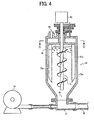
- the developer container 51 includes a developer container main body 51a having an inverted cone funnel shape, of which diameter is gradually reduced toward a discharge opening 70.
- the developer container 51 further includes a developer supply opening 69 at the top thereof, and the discharge opening 70 at the bottom thereof.
- an agitation part including a first agitation member 71 and second agitation members 72a and 72b is provided.
- the first and second agitation members 71, 72a, and 72b are provided around a rotation shaft of the agitation part, which includes a center of a cross-section in the horizontal direction of the developer container main body 51a, and the first agitation member 71 is disposed interior to the second agitation members 72a and 72b in the center of the developer container main body 51a.
- the first agitation member 71 includes a screw auger rotated in a direction such that the developer is moved upward.
- the second agitation members 72a and 72b are disposed exterior to the first agitation member 71 in the developer container main body 51a, and include stirring paddles capable of rotating around the rotation shaft of the first agitation member 71.
- the second agitation members 72a and 72b are provided on opposite sides relative to a center of the rotation shaft of the first agitation member 71, and respectively have a longitudinal direction in a vertical direction of the developer container 51.
- a base edge of each of the second agitation members 72a and 72b is fixed to a flange 74 integrally provided on the rotation shaft of the first agitation member 71. Accordingly, the first agitation member 71 moves the developer in a direction opposite to a direction of falling of the developer while the second agitation members 72a and 72b are rotated in a direction perpendicular to the direction of falling of the developer to prevent the developer from moving downward.
- FIG. 5 is a cross-sectional view illustrating the developer container 51 along a line C-C in FIG. 4 .
- the second agitation members 72a and 72b are respectively provided in the vicinity of edges of the flange 74 at an angle ⁇ ° such that the developer is moved from an inner wall side of the developer container main body 51a toward the rotation shaft of the first agitation member 71 as indicated by an arrow D1 when the second agitation members 72a and 72b are rotated in a clockwise direction as indicated by an arrow F1 in FIG. 5 .
- the second agitation members 72a and 72b are respectively provided as close as possible to the inner wall of the developer container main body 51a without causing problems of the rotation thereof so as to maximize agitation area within a cross-section of the developer container 51.
- the first agitation member 71 and the second agitation members 72a and 72b are configured to be rotated in directions different from each other. Accordingly, the developer is moved in different directions in the developer container main body 51a by the rotation of the first agitation member 71 and the second agitation members 72a and 72b.
- the first agitation member 71 is configured to be rotated in a direction indicated by an arrow F2 in FIG. 5 such that the developer is prevented from moving downward, and moved upward.
- the second agitation members 72a and 72b are configured to'be rotated in a direction indicated by the arrow F1 in FIG. 5 , which is opposite to the rotation direction of the first agitation member 71.
- the developer is moved in a direction indicated by an arrow D2 in FIG. 5 .
- the developer is moved upward as indicated by an arrow A in FIG. 6 , which is a direction opposite to the direction of falling of the developer.
- the second agitation members 72a and 72b are rotated in a clockwise direction as indicated by the arrow F1 in FIG. 5 , which is a direction perpendicular to the direction of falling of the developer to prevent the developer from moving downward, the developer is moved in the direction indicated by the arrow D1 in FIG. 5 , which is different from the direction of movement of the developer indicated by the arrow D2 caused by the rotation of the first agitation member 71.
- the developer is agitated to move in several different directions in the developer container 51.
- the first agitation member 71 and the second agitation members 72a and 72b respectively move the developer in directions different from each other in the horizontal cross-section of the developer container 51 by rotation thereof. A more detailed description of this movement of the developer in different directions can be given with reference to FIG. 6 .
- FIG. 6 is a vertical cross-sectional view illustrating the developer container 51 in FIG. 4 .
- the developer moving downward by gravity is moved upward by the rotation of the first agitation member 71 as indicated by the arrow A in FIG. 6 .
- the developer out of the agitation area of the first agitation member 71 and that moved upward to the top of the toner container 51 is collected from a peripheral portion of the developer container 51 and moved to the center thereof by the rotation of the second agitation members 72a and 72b as indicated by an arrow B in FIG. 6 . Accordingly, the developer reaches the first agitation member 71 to be agitated by the first agitation member 71 again. Therefore, as illustrated in FIG.
- the developer is convectively circulated in the developer container 51 so that the developer is agitated efficiently by using both the first agitation member 71 and the second agitation members 72a and 72b.
- the carrier and toner included in the developer contact each other more easily and the developer is more reliably applied to the developer.
- the developer is agitated to move in several different directions and convectively circulated in the developer container 51 by the rotations of the first agitation member 71 and the second agitation members 72a and 72b.
- the developer is efficiently mixed in the developer container 51, decreasing damage to and stress on the developer.
- the developer is not likely to be efficiently mixed in the developer container 51 using only the first agitation member 71 because the developer is not convectively circulated reliably in the developer container 51 only by the rotation of the first agitation member 71.
- one possible technique to efficiently agitate the developer in the developer container 51 is to increase a rotation speed of the first agitation member 71, doing so also increases a moving speed of the developer. When being moved upward at an increased speed, the developer collides against the inner wall of the developer container main body 51a with a greater force, increasing damage to the developer.
- the configuration of the present exemplary embodiment, in which the first agitation member 71 and the second agitation members 72a and 72b are provided in the developer container 51, enables the developer to be reliably agitated to move in several different directions and convectively circulated within the developer container 51.
- the developer is mixed efficiently and sufficiently in the developer container 51 without increasing the rotation speed of each of the first agitation member 71 and the second agitation members 72a and 72b, thereby decreasing damage and stress to the developer.
- the developer is agitated to move in several different directions and convectively circulated also in a horizontal cross-sectional direction. Accordingly, the developer is charged efficiently because the carrier and the toner included in the developer contact each other more frequently.
- an amount of the developer discharged from the developer container 51 is almost identical to an amount of the developer introduced into the developer container 51. Accordingly, the developer is discharged from the developer container 51 without excess or deficiency even when the agitation part is provided to prevent the developer from moving downward.
- the developer container 51 functions as a buffer to store a predetermined or desired amount of the developer therein until the developer is discharged therefrom, preventing discharge of unmixed developer.
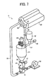
- FIG. 7 is a perspective view illustrating a means for controlling the discharge amount of the developer employed in the developing device 5 illustrated in FIG. 2 .
- the developing device 5 includes a rotary feeder 53 serving as the means for controlling the discharge amount of the developer at the discharge opening 70 of the developer container 51, provided in front of the shared pathway 77.
- the rotary feeder 53 serves as a rotary valve, a rotation speed of which is controlled by a motor 61 that rotates the rotary feeder 53.
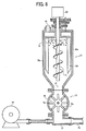
- FIG. 8 is a vertical cross-sectional view illustrating the developing device 5 in FIG. 7 .
- the rotary feeder 53 includes a rotor 75 having a plurality of blades 75a extending radially from a central shaft and a stator 76 covering the rotor 75.
- the rotation speed of the rotary feeder 53 is controlled so as to control the discharge amount of the developer.
- the discharge amount of the developer is set based on the rotation speed of the rotary feeder 53. Control of the discharge amount of the developer is important in order to obtain uniformly mixed developer.
- the toner density and the charge of the developer collected to the developer container 51 tend to be uneven.
- the amount of the fresh toner supplied to the developer in the developer container 51 may change depending on the amount of the toner consumed for development. Consequently, agitation time required to apply a sufficient charge to the developer to be discharged to the developing unit 50 may also change. More specifically, it is not necessary to agitate the developer when no fresh toner is supplied from the toner cartridge 52. On the other hand, a longer time is required to sufficiently agitate the developer when a larger amount of fresh toner is supplied from the toner cartridge 52. Furthermore, because the charge of the developer may change depending on temperature and humidity, the same agitation time cannot be set for the same developer amount under different environmental conditions.
- agitation of the developer needs to be controlled based on a state of the developer introduced into the developer container 51.
- a rotation speed of the agitation part is increased when it is difficult to sufficiently charge the developer due to a larger amount of supply of the fresh toner from the toner cartridge 52 or higher humidity.
- the rotation of the agitation part is stopped when no fresh toner is supplied.
- an amount of the developer moving down to the discharge opening 70 may decrease when the rotation speed of the agitation part is increased because the agitation members 72a and 72b are rotated in a direction for preventing the developer from moving downward.
- the developer container 51 functions as a buffer for keeping a predetermined or desired amount of the developer agitated by the agitation part therein. Therefore, a difference between an amount of the developer discharged from the developer container 51 and an amount of the developer moving down to the discharge opening 70, if any, can be absorbed. However, the amount of the developer kept in the developer container 51 tends to be gradually reduced depending how the rotation of the agitation part is controlled.
- a constant amount of the developer is returned to the developing unit 50 regardless of the control state of the rotation of the agitation part, thus preventing a change in the amount of the developer conveyed to the developing unit 50.
- the motor 54 serving as a driving source may include a stepper motor, a step count of which is controlled so as to adjust the rotation speed of the rotary feeder 53 to control the amount of the developer conveyed to the developing unit 50.
- FIG. 9 is a vertical cross-sectional view illustrating another example of the means for controlling the discharge amount of the developer employed in the developing device 5 illustrated in FIG. 2 .
- a butterfly valve 78 of which an opening angle to a flow path is changed by an angle of rotation thereof, is used as the means for controlling the discharge amount of the developer.
- the opening angle of the butterfly valve 78 is controlled by controlling the rotation speed of the motor 54.
- the amount of the developer discharged from the developer container 51 can be controlled regardless of the control state of the rotation of the agitation part. Accordingly, a constant amount of the developer can be reliably conveyed to the developing unit 50, preventing any insufficiency of developer in the developing unit 50 from arising.
- FIGS. 10A to 10C A variation of the agitation part provided in the developer container 51 is illustrated in FIGS. 10A to 10C .
- the developer container 51 according to the variation example includes a plurality of stirring paddles each serving as an agitation member in horizontal and vertical directions.
- Each of the stirring paddles has a rotation shaft extending in a horizontal direction, which is perpendicular to the direction of falling of the developer.
- FIG. 10A is a cross-sectional view illustrating the developer container 51 of the variation example along a line E-E in FIG. 10B .
- a stirring paddle 100 includes a rotation shaft 100A extending in a horizontal direction, which is perpendicular to the direction of falling of the developer.
- the rotation shaft 100A is provided on a plurality of positions in the developer container 51 in a horizontal direction and along the direction of falling of the developer.
- the rotation shaft 100A is extended in the horizontal direction so that the stirring paddle 100 can be arranged within a storage space for the developer when a horizontal cross-section of the developer container 51 is rectangular. As a result, even portions in the vicinity of corners of the horizontal cross-section of the developer container 51 can be set as the agitation area.
- the developer container 51 of the variation example includes the plurality of stirring paddles 100 along the direction of falling of the developer, as well as in the horizontal direction of the cross-section of the developer container 51.
- the plurality of stirring paddles 100 provided in the horizontal direction is rotated in directions opposite to each other as indicated by arrows in FIG. 10B .
- the plurality of stirring paddles 100 is respectively rotated in the directions for preventing the developer from moving downward. As a result, the developer is agitated in directions so as not to fall down and to be convectively circulated in the developer container 51.
- FIG. 10B the developer container 51 of the variation example includes the plurality of stirring paddles 100 along the direction of falling of the developer, as well as in the horizontal direction of the cross-section of the developer container 51.
- the plurality of stirring paddles 100 provided in the horizontal direction is rotated in directions opposite to each other as indicated by arrows in FIG. 10B .
- the plurality of stirring paddles 100 is respectively rotated in the directions for preventing the developer from moving downward
- the developer is prevented from moving downward but instead moved upward in a center of the horizontal cross-section of the developer container 51 where the plurality of stirring paddles 100 is provided close to each other. After being moved out of the center of the cross-section of the developer container 51, the developer is then moved downward along the rotation directions of the plurality of stirring paddles 100 to the discharge opening 70 provided on the bottom of the developer container 51.
- the directions of movement of the developer are indicated by arrows F and F'.
- the developer container 51 includes the plurality of stirring paddles 100 in the horizontal direction thereof and along the direction of falling of the developer. Because the plurality of stirring paddles 100 is rotated in directions different from each other, the developer can be convectively circulated reliably in the developer container 51. Therefore, in contrast to the configuration in which the developer is moved only in the direction of falling thereof, the developer is sufficiently dispersed and mixed in the developer container 51 with the configuration described above. As a result, the toner and the carrier contact each other more frequently, increasing chargeability of the toner and preventing a decrease in density of the developer.
- the rotation shafts 100A of the plurality of stirring paddles 100 provided along the direction of falling of the developer are not limited to being provided parallel to each other, and may be placed perpendicular to each other.
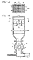
- FIG. 11A is a cross-sectional view of the developer container 51 along a H-H in FIG. 11B .
- rotation shafts 200A of stirring paddles 200 provided in the direction of falling of the developer are provided perpendicular to each other in a horizontal direction.
- Such a configuration enables the developer to be convectively circulated more reliably in the developer container 51 so that the toner and the carrier are agitated sufficiently, improving chargeability of the developer.
- the number of constituent elements, locations, shapes and so forth of the constituent elements are not limited to any of the structure for performing the methodology illustrated in the'drawings.
Landscapes
- Physics & Mathematics (AREA)
- General Physics & Mathematics (AREA)
- Dry Development In Electrophotography (AREA)
Applications Claiming Priority (1)
| Application Number | Priority Date | Filing Date | Title |
|---|---|---|---|
| JP2007146952A JP4999166B2 (ja) | 2007-06-01 | 2007-06-01 | 現像装置および画像形成装置 |
Publications (1)
| Publication Number | Publication Date |
|---|---|
| EP1998231A1 true EP1998231A1 (fr) | 2008-12-03 |
Family
ID=39549281
Family Applications (1)
| Application Number | Title | Priority Date | Filing Date |
|---|---|---|---|
| EP08156979A Withdrawn EP1998231A1 (fr) | 2007-06-01 | 2008-05-27 | Dispositif de développement et appareil de formation d'images l'incluant |
Country Status (3)
| Country | Link |
|---|---|
| US (1) | US8036576B2 (fr) |
| EP (1) | EP1998231A1 (fr) |
| JP (1) | JP4999166B2 (fr) |
Cited By (1)
| Publication number | Priority date | Publication date | Assignee | Title |
|---|---|---|---|---|
| EP3037891A1 (fr) * | 2014-12-24 | 2016-06-29 | Canon Finetech Inc. | Appareil de transport de révélateur et appareil de développement |
Families Citing this family (21)
| Publication number | Priority date | Publication date | Assignee | Title |
|---|---|---|---|---|
| JP5277566B2 (ja) | 2007-05-31 | 2013-08-28 | 株式会社リコー | 現像装置および画像形成装置 |
| US8000638B2 (en) * | 2008-06-24 | 2011-08-16 | Ricoh Company, Ltd. | Developing device using two-component developing agent and image forming apparatus provided with same |
| JP5321112B2 (ja) * | 2008-09-11 | 2013-10-23 | 株式会社リコー | 現像装置及び画像形成装置 |
| JP5463654B2 (ja) | 2008-11-20 | 2014-04-09 | 株式会社リコー | 現像装置および画像形成装置 |
| JP2010134265A (ja) | 2008-12-05 | 2010-06-17 | Ricoh Co Ltd | 現像装置及び画像形成装置 |
| JP5347611B2 (ja) * | 2009-03-18 | 2013-11-20 | 株式会社リコー | 現像装置および画像形成装置 |
| JP5193923B2 (ja) * | 2009-03-30 | 2013-05-08 | シャープ株式会社 | 現像装置および画像形成装置 |
| JP5445168B2 (ja) | 2010-01-25 | 2014-03-19 | 株式会社リコー | 画像形成装置 |
| JP5447036B2 (ja) * | 2010-03-16 | 2014-03-19 | 株式会社リコー | 現像装置および画像形成装置 |
| JP2011196450A (ja) | 2010-03-18 | 2011-10-06 | Ricoh Co Ltd | 駆動装置および画像形成装置 |
| US8818219B2 (en) * | 2010-07-08 | 2014-08-26 | Kabushiki Kaisha Toshiba | Image forming apparatus and toner charge amount adjustment method of the image forming apparatus |
| JP5811442B2 (ja) | 2010-08-26 | 2015-11-11 | 株式会社リコー | 現像装置及び画像形成装置 |
| JP5569260B2 (ja) | 2010-08-27 | 2014-08-13 | 株式会社リコー | 現像装置および画像形成装置 |
| JP2012078786A (ja) | 2010-09-08 | 2012-04-19 | Ricoh Co Ltd | 現像装置および画像形成装置 |
| US8688012B2 (en) | 2010-11-04 | 2014-04-01 | Ricoh Company, Ltd. | Developing device and image forming apparatus |
| US8737886B2 (en) * | 2010-12-20 | 2014-05-27 | Samsung Electronics Co., Ltd. | Image forming apparatus and method |
| JP5742008B2 (ja) | 2011-03-10 | 2015-07-01 | 株式会社リコー | 現像装置および画像形成装置 |
| JP2014178426A (ja) * | 2013-03-14 | 2014-09-25 | Ricoh Co Ltd | 現像剤搬送装置、現像装置及び画像形成装置 |
| JP2016006471A (ja) | 2014-05-30 | 2016-01-14 | 株式会社リコー | 画像形成装置 |
| JP2021086020A (ja) | 2019-11-28 | 2021-06-03 | ヒューレット−パッカード デベロップメント カンパニー エル.ピー.Hewlett‐Packard Development Company, L.P. | 現像室用通気路を有する画像形成システム |
| JP7548070B2 (ja) | 2021-03-08 | 2024-09-10 | 株式会社リコー | トナー残量検出装置及び画像形成装置 |
Citations (9)
| Publication number | Priority date | Publication date | Assignee | Title |
|---|---|---|---|---|
| US3191642A (en) * | 1962-09-24 | 1965-06-29 | Nissan Chemical Ind Ltd | Automatic feeder of pulverulent body |
| JPH04198966A (ja) | 1990-11-28 | 1992-07-20 | Minolta Camera Co Ltd | 画像形成装置 |
| EP0652493A2 (fr) | 1993-11-10 | 1995-05-10 | Sharp Kabushiki Kaisha | Dispositif de développement |
| JPH11143196A (ja) * | 1997-11-05 | 1999-05-28 | Ricoh Co Ltd | 画像形成装置 |
| JP2003292156A (ja) | 2002-04-01 | 2003-10-15 | Ricoh Co Ltd | 粉体供給装置及び粉体供給方法 |
| US20070079893A1 (en) | 2005-10-11 | 2007-04-12 | Xerox Corporation | Continuity-detecting method of dispensing particles, a particle filling line and apparatus for dispensing particles |
| US20070154242A1 (en) | 2005-12-20 | 2007-07-05 | Junichi Matsumoto | Developing device for developing latent images to toner images |
| US20070274740A1 (en) | 2006-05-25 | 2007-11-29 | Natsumi Katoh | Developing device and image forming apparatus |
| EP1998232A1 (fr) * | 2007-05-31 | 2008-12-03 | Ricoh Company, Ltd. | Dispositif de développement et appareil de formation d'images |
Family Cites Families (27)
| Publication number | Priority date | Publication date | Assignee | Title |
|---|---|---|---|---|
| JPS50105844U (fr) * | 1974-02-07 | 1975-08-30 | ||
| US4207995A (en) * | 1978-01-09 | 1980-06-17 | Refreshment Machinery Incorporated | Dispensing canister with cooperating screw and agitator |
| US4171165A (en) * | 1978-07-17 | 1979-10-16 | Diamond Insulation Industries, Inc. | Cellulose insulation storage bin with improved debridger |
| JPS60250373A (ja) * | 1984-05-28 | 1985-12-11 | Fuji Xerox Co Ltd | トナ−補給装置 |
| CN1003659B (zh) * | 1986-02-06 | 1989-03-22 | 株式会社东芝 | 洗衣机等的洗涤剂供给装置 |
| US5087546A (en) * | 1988-12-07 | 1992-02-11 | Canon Kabushiki Kaisha | Device for continuously mixing powder and process for producing toner for developing electrostatic image |
| JPH07295322A (ja) | 1994-04-26 | 1995-11-10 | Hitachi Ltd | カラー画像形成装置 |
| JP3391926B2 (ja) * | 1995-02-06 | 2003-03-31 | 株式会社リコー | 画像形成装置及びその現像装置 |
| JP3400631B2 (ja) * | 1995-12-28 | 2003-04-28 | 株式会社リコー | トナー供給装置 |
| JPH1039617A (ja) | 1996-07-18 | 1998-02-13 | Ricoh Co Ltd | 現像装置及び該装置を用いた画像形成装置 |
| JPH11143192A (ja) | 1997-11-10 | 1999-05-28 | Minolta Co Ltd | 現像装置 |
| JP2001188408A (ja) | 1999-12-28 | 2001-07-10 | Kyocera Mita Corp | 二成分系現像剤用現像装置 |
| DE60141310D1 (de) * | 2000-05-26 | 2010-04-01 | Kyocera Mita Corp | Tonerkassette mit Tonerrührer |
| JP2002006598A (ja) * | 2000-06-27 | 2002-01-09 | Kyocera Mita Corp | トナーカートリッジ |
| JP2002251070A (ja) | 2001-02-23 | 2002-09-06 | Ricoh Co Ltd | 現像装置・画像形成装置 |
| JP4095875B2 (ja) * | 2001-10-30 | 2008-06-04 | 株式会社リコー | 現像剤収納容器及び画像形成装置 |
| US6882816B2 (en) * | 2002-02-19 | 2005-04-19 | Matsushita Electric Industrial Co., Ltd. | Developing device with developer circulating path |
| JP3982346B2 (ja) * | 2002-06-28 | 2007-09-26 | コニカミノルタビジネステクノロジーズ株式会社 | 画像形成装置のトナーカートリッジ |
| JP4198966B2 (ja) | 2002-10-17 | 2008-12-17 | 株式会社東芝 | 半導体装置の製造方法 |
| JP3985753B2 (ja) * | 2003-08-19 | 2007-10-03 | コニカミノルタビジネステクノロジーズ株式会社 | 画像形成装置 |
| JP4276935B2 (ja) * | 2003-12-26 | 2009-06-10 | 株式会社リコー | 画像形成装置 |
| JP4614332B2 (ja) * | 2004-06-18 | 2011-01-19 | 株式会社リコー | 現像剤劣化検知方法、現像剤劣化検知装置、現像装置、画像形成装置及び画像形成方法 |
| JP2006163292A (ja) * | 2004-12-10 | 2006-06-22 | Ricoh Co Ltd | 現像装置 |
| JP4737541B2 (ja) * | 2005-09-05 | 2011-08-03 | 株式会社リコー | 現像剤搬送装置及び画像形成装置 |
| JP4889008B2 (ja) * | 2005-09-07 | 2012-02-29 | 株式会社リコー | 現像剤搬送装置及び画像形成装置 |
| JP4641937B2 (ja) * | 2005-12-27 | 2011-03-02 | シャープ株式会社 | トナー補給装置を備えた画像形成装置 |
| JP4853963B2 (ja) * | 2006-05-15 | 2012-01-11 | 株式会社リコー | 現像装置、プロセスカートリッジ、及び、画像形成装置 |
-
2007
- 2007-06-01 JP JP2007146952A patent/JP4999166B2/ja not_active Expired - Fee Related
-
2008
- 2008-05-27 EP EP08156979A patent/EP1998231A1/fr not_active Withdrawn
- 2008-05-30 US US12/129,961 patent/US8036576B2/en not_active Expired - Fee Related
Patent Citations (9)
| Publication number | Priority date | Publication date | Assignee | Title |
|---|---|---|---|---|
| US3191642A (en) * | 1962-09-24 | 1965-06-29 | Nissan Chemical Ind Ltd | Automatic feeder of pulverulent body |
| JPH04198966A (ja) | 1990-11-28 | 1992-07-20 | Minolta Camera Co Ltd | 画像形成装置 |
| EP0652493A2 (fr) | 1993-11-10 | 1995-05-10 | Sharp Kabushiki Kaisha | Dispositif de développement |
| JPH11143196A (ja) * | 1997-11-05 | 1999-05-28 | Ricoh Co Ltd | 画像形成装置 |
| JP2003292156A (ja) | 2002-04-01 | 2003-10-15 | Ricoh Co Ltd | 粉体供給装置及び粉体供給方法 |
| US20070079893A1 (en) | 2005-10-11 | 2007-04-12 | Xerox Corporation | Continuity-detecting method of dispensing particles, a particle filling line and apparatus for dispensing particles |
| US20070154242A1 (en) | 2005-12-20 | 2007-07-05 | Junichi Matsumoto | Developing device for developing latent images to toner images |
| US20070274740A1 (en) | 2006-05-25 | 2007-11-29 | Natsumi Katoh | Developing device and image forming apparatus |
| EP1998232A1 (fr) * | 2007-05-31 | 2008-12-03 | Ricoh Company, Ltd. | Dispositif de développement et appareil de formation d'images |
Cited By (2)
| Publication number | Priority date | Publication date | Assignee | Title |
|---|---|---|---|---|
| EP3037891A1 (fr) * | 2014-12-24 | 2016-06-29 | Canon Finetech Inc. | Appareil de transport de révélateur et appareil de développement |
| US9977369B2 (en) | 2014-12-24 | 2018-05-22 | Canon Finetech Nisca Inc. | Developer conveying apparatus and developing apparatus |
Also Published As
| Publication number | Publication date |
|---|---|
| JP2008299196A (ja) | 2008-12-11 |
| JP4999166B2 (ja) | 2012-08-15 |
| US20080298844A1 (en) | 2008-12-04 |
| US8036576B2 (en) | 2011-10-11 |
Similar Documents
| Publication | Publication Date | Title |
|---|---|---|
| US8036576B2 (en) | Developing device including a stirring mechanism for a two-component developer and image forming apparatus including same | |
| EP1998232B1 (fr) | Dispositif de développement et appareil de formation d'images | |
| JP5660312B2 (ja) | 現像剤搬送装置、現像剤収容器、現像装置、プロセスユニット及び画像形成装置 | |
| JP4846828B2 (ja) | 現像装置及びこれを用いる画像形成装置 | |
| US9069284B2 (en) | Image forming apparatus and powder transport unit | |
| US20090123174A1 (en) | Image forming apparatus and image forming method | |
| CN101887226A (zh) | 显影装置和使用该显影装置的图像形成设备 | |
| CN101154077A (zh) | 粉体搅拌装置、显影装置和装有显影装置的图像形成装置 | |
| US8036575B2 (en) | Development device, image forming apparatus, and process cartridge having compact structure for discharging developer | |
| US20100226688A1 (en) | Developing device, process cartridge and image forming apparatus | |
| JP5590733B2 (ja) | 現像装置及びそれを備えた画像形成装置 | |
| JP2009237043A (ja) | 現像装置及びこれを用いた画像形成装置 | |
| JP5005792B2 (ja) | 現像装置およびそれを備えた画像形成装置 | |
| US7904003B2 (en) | Developing device and image forming apparatus | |
| JP5284002B2 (ja) | 現像装置及びこれを用いる画像形成装置 | |
| US12248257B2 (en) | Developing apparatus having a sealed developer opening | |
| JP2010038939A (ja) | 現像装置及びこれを用いる画像形成装置 | |
| JP5481319B2 (ja) | 現像装置及びそれを備えた画像形成装置 | |
| JP5165493B2 (ja) | 現像装置及びこれを用いる画像形成装置 | |
| JP4777184B2 (ja) | 中間トナー補給装置、これを備えた現像装置および画像形成装置 | |
| JP7695128B2 (ja) | 現像装置および画像形成装置 | |
| JP7353885B2 (ja) | 現像装置、カートリッジ、画像形成装置 | |
| JP2025114016A (ja) | トナー収容容器 | |
| WO2026009993A1 (fr) | Appareil de développement | |
| JP2025042852A (ja) | 粉体搬送装置、現像装置及び画像形成装置 |
Legal Events
| Date | Code | Title | Description |
|---|---|---|---|
| PUAI | Public reference made under article 153(3) epc to a published international application that has entered the european phase |
Free format text: ORIGINAL CODE: 0009012 |
|
| AK | Designated contracting states |
Kind code of ref document: A1 Designated state(s): AT BE BG CH CY CZ DE DK EE ES FI FR GB GR HR HU IE IS IT LI LT LU LV MC MT NL NO PL PT RO SE SI SK TR |
|
| AX | Request for extension of the european patent |
Extension state: AL BA MK RS |
|
| 17P | Request for examination filed |
Effective date: 20090312 |
|
| AKX | Designation fees paid |
Designated state(s): DE FR GB |
|
| 17Q | First examination report despatched |
Effective date: 20111012 |
|
| STAA | Information on the status of an ep patent application or granted ep patent |
Free format text: STATUS: THE APPLICATION IS DEEMED TO BE WITHDRAWN |
|
| 18D | Application deemed to be withdrawn |
Effective date: 20171201 |