EP1998598A1 - Procédé destiné à la graphitisation de carbones - Google Patents
Procédé destiné à la graphitisation de carbones Download PDFInfo
- Publication number
- EP1998598A1 EP1998598A1 EP07109442A EP07109442A EP1998598A1 EP 1998598 A1 EP1998598 A1 EP 1998598A1 EP 07109442 A EP07109442 A EP 07109442A EP 07109442 A EP07109442 A EP 07109442A EP 1998598 A1 EP1998598 A1 EP 1998598A1
- Authority
- EP
- European Patent Office
- Prior art keywords
- carbon
- treated
- fields
- radio frequency
- graphitization
- Prior art date
- Legal status (The legal status is an assumption and is not a legal conclusion. Google has not performed a legal analysis and makes no representation as to the accuracy of the status listed.)
- Withdrawn
Links
- 238000000034 method Methods 0.000 title claims abstract description 54
- OKTJSMMVPCPJKN-UHFFFAOYSA-N Carbon Chemical compound [C] OKTJSMMVPCPJKN-UHFFFAOYSA-N 0.000 title claims abstract description 50
- 229910052799 carbon Inorganic materials 0.000 title claims abstract description 23
- 239000000463 material Substances 0.000 claims abstract description 68
- 230000005672 electromagnetic field Effects 0.000 claims abstract description 17
- 238000011282 treatment Methods 0.000 claims abstract description 16
- 229910002804 graphite Inorganic materials 0.000 claims abstract description 13
- 239000010439 graphite Substances 0.000 claims abstract description 13
- 238000010438 heat treatment Methods 0.000 claims abstract description 11
- 239000000843 powder Substances 0.000 claims abstract description 5
- 239000011230 binding agent Substances 0.000 claims abstract description 4
- 239000007833 carbon precursor Substances 0.000 claims abstract description 4
- 239000011347 resin Substances 0.000 claims abstract description 3
- 229920005989 resin Polymers 0.000 claims abstract description 3
- 238000005087 graphitization Methods 0.000 claims description 34
- 238000006243 chemical reaction Methods 0.000 claims description 17
- 230000008569 process Effects 0.000 claims description 13
- 230000001965 increasing effect Effects 0.000 claims description 8
- 230000009471 action Effects 0.000 claims description 7
- 238000004140 cleaning Methods 0.000 claims description 6
- 239000011358 absorbing material Substances 0.000 claims description 4
- 230000007847 structural defect Effects 0.000 claims description 2
- 238000000137 annealing Methods 0.000 claims 1
- 239000000356 contaminant Substances 0.000 claims 1
- 239000003575 carbonaceous material Substances 0.000 abstract description 12
- 230000000694 effects Effects 0.000 abstract description 2
- 235000011837 pasties Nutrition 0.000 abstract 1
- 239000007789 gas Substances 0.000 description 15
- 239000002245 particle Substances 0.000 description 10
- 239000000571 coke Substances 0.000 description 9
- 238000002485 combustion reaction Methods 0.000 description 8
- 230000004992 fission Effects 0.000 description 6
- VYPSYNLAJGMNEJ-UHFFFAOYSA-N Silicium dioxide Chemical compound O=[Si]=O VYPSYNLAJGMNEJ-UHFFFAOYSA-N 0.000 description 5
- 238000010521 absorption reaction Methods 0.000 description 5
- 230000008901 benefit Effects 0.000 description 5
- 230000008878 coupling Effects 0.000 description 5
- 238000010168 coupling process Methods 0.000 description 5
- 238000005859 coupling reaction Methods 0.000 description 5
- 239000011261 inert gas Substances 0.000 description 5
- 230000005855 radiation Effects 0.000 description 5
- 238000002441 X-ray diffraction Methods 0.000 description 4
- 239000004020 conductor Substances 0.000 description 4
- 239000012535 impurity Substances 0.000 description 3
- 230000001939 inductive effect Effects 0.000 description 3
- 239000007858 starting material Substances 0.000 description 3
- 230000015572 biosynthetic process Effects 0.000 description 2
- 238000001354 calcination Methods 0.000 description 2
- 239000007795 chemical reaction product Substances 0.000 description 2
- 150000001875 compounds Chemical class 0.000 description 2
- 230000007547 defect Effects 0.000 description 2
- 238000009826 distribution Methods 0.000 description 2
- 230000006698 induction Effects 0.000 description 2
- 238000009413 insulation Methods 0.000 description 2
- 230000007246 mechanism Effects 0.000 description 2
- 229910021382 natural graphite Inorganic materials 0.000 description 2
- 239000011295 pitch Substances 0.000 description 2
- 239000002243 precursor Substances 0.000 description 2
- 239000000047 product Substances 0.000 description 2
- 239000012495 reaction gas Substances 0.000 description 2
- 230000001105 regulatory effect Effects 0.000 description 2
- 238000007669 thermal treatment Methods 0.000 description 2
- XLYOFNOQVPJJNP-UHFFFAOYSA-N water Substances O XLYOFNOQVPJJNP-UHFFFAOYSA-N 0.000 description 2
- 229910001369 Brass Inorganic materials 0.000 description 1
- RYGMFSIKBFXOCR-UHFFFAOYSA-N Copper Chemical compound [Cu] RYGMFSIKBFXOCR-UHFFFAOYSA-N 0.000 description 1
- 238000004616 Pyrometry Methods 0.000 description 1
- NINIDFKCEFEMDL-UHFFFAOYSA-N Sulfur Chemical group [S] NINIDFKCEFEMDL-UHFFFAOYSA-N 0.000 description 1
- 239000002250 absorbent Substances 0.000 description 1
- 230000002745 absorbent Effects 0.000 description 1
- 239000000654 additive Substances 0.000 description 1
- 230000000996 additive effect Effects 0.000 description 1
- 239000002194 amorphous carbon material Substances 0.000 description 1
- 238000004458 analytical method Methods 0.000 description 1
- RHZUVFJBSILHOK-UHFFFAOYSA-N anthracen-1-ylmethanolate Chemical compound C1=CC=C2C=C3C(C[O-])=CC=CC3=CC2=C1 RHZUVFJBSILHOK-UHFFFAOYSA-N 0.000 description 1
- 239000003830 anthracite Substances 0.000 description 1
- 229910021383 artificial graphite Inorganic materials 0.000 description 1
- 230000002238 attenuated effect Effects 0.000 description 1
- 239000010951 brass Substances 0.000 description 1
- 239000011329 calcined coke Substances 0.000 description 1
- 239000006229 carbon black Substances 0.000 description 1
- 229910021386 carbon form Inorganic materials 0.000 description 1
- 230000003197 catalytic effect Effects 0.000 description 1
- 230000008859 change Effects 0.000 description 1
- 239000011294 coal tar pitch Substances 0.000 description 1
- 239000010941 cobalt Substances 0.000 description 1
- 229910017052 cobalt Inorganic materials 0.000 description 1
- GUTLYIVDDKVIGB-UHFFFAOYSA-N cobalt atom Chemical compound [Co] GUTLYIVDDKVIGB-UHFFFAOYSA-N 0.000 description 1
- 238000010924 continuous production Methods 0.000 description 1
- 238000001816 cooling Methods 0.000 description 1
- 239000010949 copper Substances 0.000 description 1
- 229910052802 copper Inorganic materials 0.000 description 1
- 230000007423 decrease Effects 0.000 description 1
- 238000002050 diffraction method Methods 0.000 description 1
- 229910021389 graphene Inorganic materials 0.000 description 1
- 230000005484 gravity Effects 0.000 description 1
- 231100000206 health hazard Toxicity 0.000 description 1
- 125000005842 heteroatom Chemical group 0.000 description 1
- 238000005259 measurement Methods 0.000 description 1
- 239000000203 mixture Substances 0.000 description 1
- 238000005457 optimization Methods 0.000 description 1
- 230000001766 physiological effect Effects 0.000 description 1
- 230000002035 prolonged effect Effects 0.000 description 1
- 230000001681 protective effect Effects 0.000 description 1
- 238000000197 pyrolysis Methods 0.000 description 1
- 239000002994 raw material Substances 0.000 description 1
- 239000000126 substance Substances 0.000 description 1
- 229910052717 sulfur Inorganic materials 0.000 description 1
- 239000011593 sulfur Substances 0.000 description 1
- 239000011269 tar Substances 0.000 description 1
- 230000007723 transport mechanism Effects 0.000 description 1
- 239000003039 volatile agent Substances 0.000 description 1
Images



Classifications
-
- H—ELECTRICITY
- H05—ELECTRIC TECHNIQUES NOT OTHERWISE PROVIDED FOR
- H05B—ELECTRIC HEATING; ELECTRIC LIGHT SOURCES NOT OTHERWISE PROVIDED FOR; CIRCUIT ARRANGEMENTS FOR ELECTRIC LIGHT SOURCES, IN GENERAL
- H05B6/00—Heating by electric, magnetic or electromagnetic fields
- H05B6/02—Induction heating
- H05B6/16—Furnaces having endless cores
- H05B6/18—Furnaces having endless cores having melting basin
-
- C—CHEMISTRY; METALLURGY
- C01—INORGANIC CHEMISTRY
- C01B—NON-METALLIC ELEMENTS; COMPOUNDS THEREOF; METALLOIDS OR COMPOUNDS THEREOF NOT COVERED BY SUBCLASS C01C
- C01B32/00—Carbon; Compounds thereof
- C01B32/20—Graphite
- C01B32/205—Preparation
-
- C—CHEMISTRY; METALLURGY
- C04—CEMENTS; CONCRETE; ARTIFICIAL STONE; CERAMICS; REFRACTORIES
- C04B—LIME, MAGNESIA; SLAG; CEMENTS; COMPOSITIONS THEREOF, e.g. MORTARS, CONCRETE OR LIKE BUILDING MATERIALS; ARTIFICIAL STONE; CERAMICS; REFRACTORIES; TREATMENT OF NATURAL STONE
- C04B35/00—Shaped ceramic products characterised by their composition; Ceramics compositions; Processing powders of inorganic compounds preparatory to the manufacturing of ceramic products
- C04B35/515—Shaped ceramic products characterised by their composition; Ceramics compositions; Processing powders of inorganic compounds preparatory to the manufacturing of ceramic products based on non-oxide ceramics
- C04B35/52—Shaped ceramic products characterised by their composition; Ceramics compositions; Processing powders of inorganic compounds preparatory to the manufacturing of ceramic products based on non-oxide ceramics based on carbon, e.g. graphite
- C04B35/522—Graphite
-
- C—CHEMISTRY; METALLURGY
- C04—CEMENTS; CONCRETE; ARTIFICIAL STONE; CERAMICS; REFRACTORIES
- C04B—LIME, MAGNESIA; SLAG; CEMENTS; COMPOSITIONS THEREOF, e.g. MORTARS, CONCRETE OR LIKE BUILDING MATERIALS; ARTIFICIAL STONE; CERAMICS; REFRACTORIES; TREATMENT OF NATURAL STONE
- C04B2235/00—Aspects relating to ceramic starting mixtures or sintered ceramic products
- C04B2235/65—Aspects relating to heat treatments of ceramic bodies such as green ceramics or pre-sintered ceramics, e.g. burning, sintering or melting processes
- C04B2235/66—Specific sintering techniques, e.g. centrifugal sintering
- C04B2235/667—Sintering using wave energy, e.g. microwave sintering
Definitions
- the invention relates to a method for graphitizing non-graphitic carbon or for increasing the degree of graphitization of partially graphitized carbon by the action of electromagnetic fields.
- Numerous essentially carbon-based materials which do not have the graphite-typical structure of regularly stacked graphene layers can preferably be graphitized by thermal treatment at temperatures above 2200 ° C.
- the temperature required for graphitization can be generated, for example, by inducing eddy currents by the action of an alternating electromagnetic field in the carbon to be graphitized (inductive graphitization).
- the device for graphitization comprises an oven with a burner tube positioned underneath, as well as waveguides for microwaves, which lead into the oven and serve to allow microwaves to act on the uppermost layer of the carbon powder in the burner tube from above.
- a device for the continuous supply of graphitizing carbon powder, and below the combustion tube provides a device for the continuous removal of the graphitized material, so that the level in the combustion tube is constant.
- the upper end of the combustion tube protrudes into the lower part of the furnace, whose cross-section narrows downwards.
- the combustion tube and the lower part of the furnace are filled with the carbon powder.
- the furnace and the upper part of the combustion tube are provided with thermal insulation.
- the lower part of the combustion tube has a reduced thermal insulation, so that here the graphitized material can cool down.
- the uppermost layer of the carbon powder is located at the top of the combustion tube projecting into the furnace. Below this uppermost carbon layer is formed a high temperature zone in which the graphitization occurs. Due to the continuous refilling of further carbon powder from above, the surface of the high temperature zone is always covered by a layer of freshly supplied, not yet heated carbon powder, which thermally isolated the high temperature zone. After passing the high temperature zone, the carbon material passes through the cooling zone.
- the peculiarity of this method is that the temperature necessary for the graphitization of the carbon powder is achieved by direct heating of the material to be graphitized.
- the microwave energy is supplied via waveguides. These waveguides must be designed for the frequency used, since they only transport certain microwave modes.
- the waveguides open into the cavity of the furnace, which forms a microwave resonator. At its bottom, which is formed by the uppermost layer of the continuously refilled carbon powder, a total reflection of the microwave attenuated by energy absorption of the material takes place.
- the phase and mode position of the microwave radiation must be tuned very precisely, so that it reaches a maximum field strength in the resonator at the location of the high-temperature zone and the energy coupling becomes efficient. If the conductivity of the carbon powder changes as a result of the ongoing graphitization process, the resonator is detuned. Therefore educt addition and product removal must be regulated very accurately, or the phase and mode shape of the microwave radiation must be readjusted. The overall system is therefore relatively demanding in terms of regulatory effort.
- the microwave conductors must be made of a conductive material (typically copper or brass).
- a conductive material typically copper or brass.
- gaseous volatiles are often driven out of the carbon material, which contain heteroatoms such as sulfur.
- Metallic microwave conductors are in a device according to U.S. Patent 6,375,918 therefore exposed to a very corrosive atmosphere.
- a device which uses microwave radiation must be shielded from the outside in a suitable manner and secured against accidental opening during operation, since microwave radiation by its physiological effect, which consists in the heating of polarizable molecules (eg water at 2.45 GHz), represents a health hazard for the operating personnel.
- microwave radiation by its physiological effect which consists in the heating of polarizable molecules (eg water at 2.45 GHz)
- polarizable molecules eg water at 2.45 GHz
- a method for inductive graphitization of non-graphitic carbon material wherein electromagnetic fields having a frequency in the range of the radio waves, ie from the frequency band of 100 kHz to 300 MHz in the zu graphitizing material can be coupled.
- the coupling is inductively, capacitively or as a combination of both mechanisms, the invention is not to be understood as bound to a particular coupling mechanism.
- radio waves over microwaves is that no resonator cavity enclosing the material to be treated is necessary to produce a field strength maximum in the zone to be heated. Instead, the field strength maximum is generated by the near field of a suitably shaped transmitting antenna, preferably an array of induction coils.
- the antenna shape can easily be adapted to the geometry of the zone to be heated. This makes the optimization of the coupling of the energy as a whole easier, since it is independent of the observance of narrow resonance conditions.
- radio waves unlike microwaves, are less physiologically sensitive because they are unable to heat water. Therefore, the requirements of the shield in the inventive method are less high than when using microwaves.
- structural defects e.g., dot defects, lattice defects, stacking failure
- structural defects can heal in materials having a distorted graphitic structure.
- the degree of graphitization can be increased with the method according to the invention.
- the degree of order of the structure can be increased by the method according to the invention.
- the method according to the invention is suitable for graphitizing non-graphitic (X-ray amorphous) carbon, provided that it is graphitizable by thermal treatment.
- non-graphitic carbon in which the d 002 value calculated from the X-ray diffraction pattern is greater than 0.344 nm.
- the d 002 value is 0.3354 nm.
- An essential parameter for achieving a high degree of graphitization is the maximum temperature reached during graphitization.
- the starting material is coke or pitch.
- the coke is already calcined or calcined prior to the graphitization according to the invention in a known manner. Previous calcination of the coke has the advantage that during treatment with the radio frequency field no or less fission gases arise. If not calcined coke is used, then the calcination takes place during the action of the radio frequency field, and in the process management, the formation of fission gases is taken into account.
- the starting material is a carbon precursor, such as a carbonizable, i. in pyrolysis in an inert gas atmosphere with high yield into carbon convertible binder, e.g. Bad luck.
- the conversion of the precursor into carbon then takes place during the electromagnetic irradiation.
- Graphite may optionally be added or admixed to the carbon material to be graphitized.
- both natural graphite and synthetic graphite are suitable, particularly preferred is the addition of the already graphitized form of the material to be graphitized in order to obtain a homogeneous end product.
- the advantage of adding graphite is an increase in the coupling efficiency at the beginning of the action of the radio-frequency field. This may be advantageous, in particular, when the material to be treated is a carbon precursor barely absorbing electromagnetic radio-frequency fields at the beginning of the treatment.
- nonabsorbent materials may also be subjected to high temperature treatment e.g. for cleaning purposes, in which the electromagnetic heating takes place from the inside.
- the carbon to be graphitized may be in bulk form, e.g. as a powder, as a paste or as a shaped body.
- the shaped body may be, for example, a compact, rod or strand.
- the carbon form to be graphitized may be coated with a carbonizable or graphitizable binder, such as e.g. Resin, pitch or tar impregnated.
- the particles of the material to be graphitized may be submicroscopic (particle size 100 nm to 1000 nm), microscopic (particle size 1 ⁇ m to 1000 ⁇ m, preferably 5 ⁇ m to 50 ⁇ m) or macroscopic (particle size 1 mm to 100 mm) particles. It is also possible to use mixtures of particles of different sizes or / and of different carbon materials.
- the electromagnetic fields are applied by means of a radio-frequency generator and an antenna.
- a radio-frequency generator and an antenna.
- Various arrangements of the antenna or multiple antennas relative to the material to be treated are possible.
- the antennas are separated from the material to be treated by a wall.
- this wall absorbs even radio frequency fields only to a much lesser extent than the material to be treated.
- the material to be treated in contrast to conventional induction furnaces, is not heated indirectly over the wall, but directly through the absorbed electromagnetic field.
- the material of the wall should be resistant to the temperatures occurring in the process for the duration of the process or should be adequately cooled.
- a wall material meeting these requirements is quartz glass.
- the material to be treated is located in a reaction vessel that does not disturb the absorption of the electromagnetic field by the material to be treated or only slightly.
- reaction vessels are used, which consist of materials such as quartz glass, the radio frequency fields absorb only to a much lesser extent than the material to be treated.
- reaction vessels made of radio frequency fields absorbing materials such as graphite can be used, but then the geometric arrangement of the reaction vessel with respect to the antenna should be designed so that the vessel material is exposed only to a weakened radio frequency field.
- the heating of the material to be treated takes place primarily directly by absorption of the radio-frequency field, and not indirectly via the absorbent wall material.
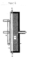
- the reactor is inside the solenoid coil shaped antenna 3 of the radio-frequency generator.
- the wall 4 of the reactor is made of quartz glass.
- the material 2 to be treated for example a bed of carbon to be graphitized, is during treatment in a crucible, tube or other reaction vessel 1 made of a material that is stable at the appropriate temperatures and does not absorb the radiated energy ,
- reaction vessels made of quartz glass are suitable.
- the antenna 3 of the radio-frequency generator is planar and extends over a surface of the material to be treated.
- the material to be treated 2 for example, a bed of carbon to be graphitized, located in a reaction vessel 1 and can by a wall 4 of a material that, in contrast to the material to be treated 2 radio frequency fields only slightly absorbed, of the antenna 3 are separated.
- the vessel 1 is exposed only to a weakened radio frequency field, therefore, a vessel 1 of a radio frequency field absorbing material such as graphite can be used here.
- the heating of the material 2 to be treated takes place within a thin layer below the planar antenna 3.
- the reactor 4 is equipped with devices 5 for the introduction of inert or reaction gas and / or the application of increased or reduced pressure.
- gases are released during the heating of the radio-frequency fields absorbing material 2, for example the fission gases which are formed during the graphitization of coke, these gases can escape unhindered from the heated zone.
- inert or reactive gases can diffuse into the thin layer of the bed or can be introduced in a targeted manner in order to support the process taking place there, for example the graphitization process, by chemical reactions and to remove the reaction products.
- the temperature distribution of the bed can be influenced by the geometry of the antenna.
- the antenna is formed, for example, with the geometry of a meander, a spiral or a radial or fence-shaped conductor arrangement.
- Frequencies from the frequency band of 100 kHz to 300 MHz are suitable for the method according to the invention. Within this band exist the areas of long wave, medium wave, short wave and ultra short wave, all of them can be used for the inventive method. Preferably, shortwave or ultrashort wave frequencies of 1 MHz to 300 MHz are used since energy absorption increases with frequency.
- the duration of exposure to the radio frequency field is a few seconds to minutes.
- the pressure and catalytic influences decisive, which temperature is reached.
- the duration of the treatment depends on how fast a temperature sufficient for the graphitization is achieved.
- the duration of the treatment can be prolonged if impurities have to be expelled and the formation of fission gases occurs or if the conversion of a precursor into carbon has to take place first.
- the method can also be carried out in such a way that the material to be treated is transported continuously through the electromagnetic field.
- the devices described above are combined with corresponding devices for supplying the treated material and for transporting the treated material.
- the device according to FIG. 2 suitable for continuous operation.
- the material transport can be carried out predominantly vertically or predominantly horizontally.
- the supply of the material to be treated takes place via a vertical transport mechanism 6, for example by means of a lifting floor or screw conveyor, against the force of gravity.
- the discharge takes place horizontally on the uppermost layer of the bed 2 of the material to be treated.
- the material to be discharged is conveyed to the removal opening 7, for example, by means of a gas pulse from the gas introduction device 5, a mechanical scraper or a vibrator.
- a device for continuous process control with one or more planar antennas 3 and mainly horizontal material transport shows FIG. 4 ,
- the material to be treated 2 is introduced at position 9 in a recessed into the surface of the turntable 8 groove happens during the rotation of the turntable 8 generated by the antennas 3 radio frequency field and is removed at position 10 ,
- the material to be treated can also be provided in individual reaction vessels, which are placed at position 9 on the turntable and taken down in position 10.
- Rhackarmes the material to be graphitized after passing through the first antenna 3 and before entering the area of the next antenna 3 are mixed. In this way it is achieved that also the material located at the edge zones is completely graphitized.
- the prior art discloses numerous devices for continuous high-temperature treatments which adapt to the method according to the invention can be such as a push-through, a working with downward material transport device such as from the U.S. Patent 6,375,918 , or a device with upward conveyance of the material to be treated into the reaction zone and parallel downward conveyance of the treated material.
- a device is for example from the European patent application EP 1 512 665 known.
- temperatures of more than 2900 ° C. can be achieved on the surface of the carbon material to be treated, as measurements by quotient pyrometry show.
- the electromagnetic energy is applied to the carbon material to be graphitized by a high-temperature-resistant radio frequency non-absorbing wall material, while in graphitization with microwaves US 6,375,918 the electromagnetic energy is applied directly to the material to be graphitized. That is, in the method according to the invention, the energy source (the antenna of the radio-frequency generator) can be separated from the reaction zone by a wall material.
- the energy source the antenna of the radio-frequency generator
- the carbon materials to be graphit tend to release corrosive gases (fission gases).
- gaseous compounds formed during the treatment can be conducted out of the reaction zone.
- cleaning gases for selective removal of certain, such as metallic impurities can be passed. This makes it possible to provide high-purity graphites.
- the graphitization or increase in the degree of graphitization achieved with the method according to the invention can be detected by X-ray powder diffractometry (XRD). Based on the diffractogram ( FIG. 5 ) can be clearly distinguished between X-ray amorphous carbons, such as cokes, on the one hand and crystalline graphite on the other hand.
- XRD X-ray powder diffractometry
- the frequency was 4 MHz, this is a released "technical frequency”.
- the average power of the radio-frequency generator used was 1.7 kW.
- reaction vessels made of quartz glass, which were not heated even by the radiated energy. In each case an inert gas atmosphere was prepared in the reactor.
- the duration of radiofrequency irradiation was 4 minutes.
- the temperature of the coke bed reached 2950 ° C, that is sufficient for graphitization temperature.
Landscapes
- Chemical & Material Sciences (AREA)
- Organic Chemistry (AREA)
- Engineering & Computer Science (AREA)
- Ceramic Engineering (AREA)
- Life Sciences & Earth Sciences (AREA)
- General Life Sciences & Earth Sciences (AREA)
- Geology (AREA)
- Inorganic Chemistry (AREA)
- Physics & Mathematics (AREA)
- Electromagnetism (AREA)
- Materials Engineering (AREA)
- Structural Engineering (AREA)
- Manufacturing & Machinery (AREA)
- Carbon And Carbon Compounds (AREA)
Priority Applications (1)
| Application Number | Priority Date | Filing Date | Title |
|---|---|---|---|
| EP07109442A EP1998598A1 (fr) | 2007-06-01 | 2007-06-01 | Procédé destiné à la graphitisation de carbones |
Applications Claiming Priority (1)
| Application Number | Priority Date | Filing Date | Title |
|---|---|---|---|
| EP07109442A EP1998598A1 (fr) | 2007-06-01 | 2007-06-01 | Procédé destiné à la graphitisation de carbones |
Publications (1)
| Publication Number | Publication Date |
|---|---|
| EP1998598A1 true EP1998598A1 (fr) | 2008-12-03 |
Family
ID=38508819
Family Applications (1)
| Application Number | Title | Priority Date | Filing Date |
|---|---|---|---|
| EP07109442A Withdrawn EP1998598A1 (fr) | 2007-06-01 | 2007-06-01 | Procédé destiné à la graphitisation de carbones |
Country Status (1)
| Country | Link |
|---|---|
| EP (1) | EP1998598A1 (fr) |
Cited By (1)
| Publication number | Priority date | Publication date | Assignee | Title |
|---|---|---|---|---|
| CN110407202A (zh) * | 2019-02-19 | 2019-11-05 | 襄阳汉江高科新能源材料有限公司 | 用于钠离子电池的石墨负极材料制备方法 |
Citations (4)
| Publication number | Priority date | Publication date | Assignee | Title |
|---|---|---|---|---|
| FR2090693A5 (fr) * | 1970-04-30 | 1972-01-14 | Kammann Fa Werner | |
| FR2472151A1 (fr) * | 1979-12-18 | 1981-06-26 | Bretagne Atel Chantiers | Four de chauffage par induction a haute temperature |
| US6375918B1 (en) | 1998-03-27 | 2002-04-23 | Mitsubishi Heavy Industries, Ltd. | Method and device for continuously burning powder carbon |
| WO2003067931A1 (fr) * | 2002-02-06 | 2003-08-14 | Touchstone Research Laboratory, Ltd. | Traitement de mousses de carbone assiste par micro-ondes |
-
2007
- 2007-06-01 EP EP07109442A patent/EP1998598A1/fr not_active Withdrawn
Patent Citations (4)
| Publication number | Priority date | Publication date | Assignee | Title |
|---|---|---|---|---|
| FR2090693A5 (fr) * | 1970-04-30 | 1972-01-14 | Kammann Fa Werner | |
| FR2472151A1 (fr) * | 1979-12-18 | 1981-06-26 | Bretagne Atel Chantiers | Four de chauffage par induction a haute temperature |
| US6375918B1 (en) | 1998-03-27 | 2002-04-23 | Mitsubishi Heavy Industries, Ltd. | Method and device for continuously burning powder carbon |
| WO2003067931A1 (fr) * | 2002-02-06 | 2003-08-14 | Touchstone Research Laboratory, Ltd. | Traitement de mousses de carbone assiste par micro-ondes |
Cited By (2)
| Publication number | Priority date | Publication date | Assignee | Title |
|---|---|---|---|---|
| CN110407202A (zh) * | 2019-02-19 | 2019-11-05 | 襄阳汉江高科新能源材料有限公司 | 用于钠离子电池的石墨负极材料制备方法 |
| CN110407202B (zh) * | 2019-02-19 | 2023-06-30 | 湖北宝乾新能源材料有限公司 | 用于钠离子电池的石墨负极材料制备方法 |
Similar Documents
| Publication | Publication Date | Title |
|---|---|---|
| EP2836297B1 (fr) | Réacteur à pression régulée | |
| Phuruangrat et al. | Preparation, characterization and photoluminescence of nanocrystalline calcium molybdate | |
| DE10260743B4 (de) | Verfahren und Anlage zum thermischen Behandeln von körnigen Feststoffen in einem Wirbelbett | |
| DE69123198T2 (de) | Verfahren und Vorrichtung zur Herstellung von Aktivkohle unter Verwendung von kohlehaltigem Material | |
| DE60319017T2 (de) | Mikrowellenbehandlung von granulaten in einem ringförmigen wirbelbett | |
| DE102019003789A1 (de) | Graphen, Vorrichtung zur Herstellung von Graphen, und Verfahren zur Herstellung von Graphen | |
| DE102019003792B4 (de) | Verfahren zur Herstellung von elektrischem Leiter und Heizelement, und das Heizelement verwendende Heizvorrichtung | |
| EP0823190B1 (fr) | Procede et dispositif de traitement thermique de materiaux dans un four a micro-ondes, et utilisation de ce procede et de ce dispositif | |
| EP2080214A1 (fr) | Dispositif et procede pour produire des plasmas de micro-ondes de forte puissance | |
| EP3245158B1 (fr) | Dispositif et procédé de fabrication de carbure de silicium | |
| DE10260742A1 (de) | Verfahren und Anlage zum thermischen Behandeln von körnigen Feststoffen in einem Wirbelbett | |
| DE102021202465A1 (de) | Reaktor und Verfahren zur Pyrolyse von kohlenwasserstoffhaltigen Fluiden | |
| DE69735130T2 (de) | Verfahren und vorrichtung zur herstellung von metallpulvern | |
| DE3525541C2 (de) | Verfahren und Vorrichtung zum Herstellen von β-Siliciumcarbid-Whiskern | |
| DE102006048814A1 (de) | Vorrichtung und Verfahren zur Erzeugung von Mikrowellenplasmen hoher Plasmadichte | |
| EP1998598A1 (fr) | Procédé destiné à la graphitisation de carbones | |
| DE2932832A1 (de) | Verfahren zur koksentschwefelung | |
| WO2009010201A2 (fr) | Procédé relevant de la métallurgie des poudres pour produire un profilé extrudé | |
| DE102007055548B4 (de) | Vorrichtung zum Eintrag von Mikrowellen in einen Reaktionsraum | |
| DE4327308C2 (de) | Verfahren und Vorrichtung zur Herstellung von polykristallinem Silizium | |
| DE10260744A1 (de) | Verfahren und Anlage zum thermischen Behandeln von körnigen Feststoffen | |
| DE102013223233A1 (de) | Verfahren und Vorrichtung zur selektiven Entfernung von Komponenten aus Gasgemischen | |
| DE102019003790B4 (de) | Verfahren zur Herstellung von amporphem Siliciumdioxid | |
| AT510612B1 (de) | Verfahren zum aufarbeiten von metallhaltigen verbundmaterialien | |
| DE102019118560A1 (de) | Pyrolysereaktor und Verfahren zur chemischen Aufbereitung von Kunststoffen |
Legal Events
| Date | Code | Title | Description |
|---|---|---|---|
| PUAI | Public reference made under article 153(3) epc to a published international application that has entered the european phase |
Free format text: ORIGINAL CODE: 0009012 |
|
| AK | Designated contracting states |
Kind code of ref document: A1 Designated state(s): AT BE BG CH CY CZ DE DK EE ES FI FR GB GR HU IE IS IT LI LT LU LV MC MT NL PL PT RO SE SI SK TR |
|
| AX | Request for extension of the european patent |
Extension state: AL BA HR MK RS |
|
| RAP1 | Party data changed (applicant data changed or rights of an application transferred) |
Owner name: SGL CARBON SE |
|
| 17P | Request for examination filed |
Effective date: 20090603 |
|
| 17Q | First examination report despatched |
Effective date: 20090710 |
|
| AKX | Designation fees paid |
Designated state(s): AT BE BG CH CY CZ DE DK EE ES FI FR GB GR HU IE IS IT LI LT LU LV MC MT NL PL PT RO SE SI SK TR |
|
| RAP1 | Party data changed (applicant data changed or rights of an application transferred) |
Owner name: SGL CARBON SE |
|
| STAA | Information on the status of an ep patent application or granted ep patent |
Free format text: STATUS: THE APPLICATION IS DEEMED TO BE WITHDRAWN |
|
| 18D | Application deemed to be withdrawn |
Effective date: 20150106 |