EP1999008B1 - Système de transfert d'hydrocarbures à déplacement horizontal - Google Patents
Système de transfert d'hydrocarbures à déplacement horizontal Download PDFInfo
- Publication number
- EP1999008B1 EP1999008B1 EP20070727488 EP07727488A EP1999008B1 EP 1999008 B1 EP1999008 B1 EP 1999008B1 EP 20070727488 EP20070727488 EP 20070727488 EP 07727488 A EP07727488 A EP 07727488A EP 1999008 B1 EP1999008 B1 EP 1999008B1
- Authority
- EP
- European Patent Office
- Prior art keywords
- duct
- transverse
- transfer system
- extending
- hydrocarbon
- Prior art date
- Legal status (The legal status is an assumption and is not a legal conclusion. Google has not performed a legal analysis and makes no representation as to the accuracy of the status listed.)
- Expired - Fee Related
Links
- 229930195733 hydrocarbon Natural products 0.000 title claims description 38
- 150000002430 hydrocarbons Chemical class 0.000 title claims description 38
- 239000004215 Carbon black (E152) Substances 0.000 title claims description 35
- 238000006073 displacement reaction Methods 0.000 title description 9
- 239000012530 fluid Substances 0.000 claims description 41
- 230000033001 locomotion Effects 0.000 claims description 29
- XLYOFNOQVPJJNP-UHFFFAOYSA-N water Substances O XLYOFNOQVPJJNP-UHFFFAOYSA-N 0.000 claims description 4
- 230000008878 coupling Effects 0.000 claims description 2
- 238000010168 coupling process Methods 0.000 claims description 2
- 238000005859 coupling reaction Methods 0.000 claims description 2
- 238000010276 construction Methods 0.000 description 5
- 239000000725 suspension Substances 0.000 description 4
- -1 LNG Chemical class 0.000 description 1
- 230000001419 dependent effect Effects 0.000 description 1
- 230000005484 gravity Effects 0.000 description 1
- 238000004519 manufacturing process Methods 0.000 description 1
- 239000000463 material Substances 0.000 description 1
- 238000012986 modification Methods 0.000 description 1
- 230000004048 modification Effects 0.000 description 1
- 230000003068 static effect Effects 0.000 description 1
Images

Classifications
-
- B—PERFORMING OPERATIONS; TRANSPORTING
- B63—SHIPS OR OTHER WATERBORNE VESSELS; RELATED EQUIPMENT
- B63B—SHIPS OR OTHER WATERBORNE VESSELS; EQUIPMENT FOR SHIPPING
- B63B27/00—Arrangement of ship-based loading or unloading equipment for cargo or passengers
- B63B27/24—Arrangement of ship-based loading or unloading equipment for cargo or passengers of pipe-lines
-
- B—PERFORMING OPERATIONS; TRANSPORTING
- B63—SHIPS OR OTHER WATERBORNE VESSELS; RELATED EQUIPMENT
- B63B—SHIPS OR OTHER WATERBORNE VESSELS; EQUIPMENT FOR SHIPPING
- B63B27/00—Arrangement of ship-based loading or unloading equipment for cargo or passengers
- B63B27/30—Arrangement of ship-based loading or unloading equipment for transfer at sea between ships or between ships and off-shore structures
- B63B27/34—Arrangement of ship-based loading or unloading equipment for transfer at sea between ships or between ships and off-shore structures using pipe-lines
-
- B—PERFORMING OPERATIONS; TRANSPORTING
- B67—OPENING, CLOSING OR CLEANING BOTTLES, JARS OR SIMILAR CONTAINERS; LIQUID HANDLING
- B67D—DISPENSING, DELIVERING OR TRANSFERRING LIQUIDS, NOT OTHERWISE PROVIDED FOR
- B67D9/00—Apparatus or devices for transferring liquids when loading or unloading ships
-
- B—PERFORMING OPERATIONS; TRANSPORTING
- B67—OPENING, CLOSING OR CLEANING BOTTLES, JARS OR SIMILAR CONTAINERS; LIQUID HANDLING
- B67D—DISPENSING, DELIVERING OR TRANSFERRING LIQUIDS, NOT OTHERWISE PROVIDED FOR
- B67D9/00—Apparatus or devices for transferring liquids when loading or unloading ships
- B67D9/02—Apparatus or devices for transferring liquids when loading or unloading ships using articulated pipes
-
- Y—GENERAL TAGGING OF NEW TECHNOLOGICAL DEVELOPMENTS; GENERAL TAGGING OF CROSS-SECTIONAL TECHNOLOGIES SPANNING OVER SEVERAL SECTIONS OF THE IPC; TECHNICAL SUBJECTS COVERED BY FORMER USPC CROSS-REFERENCE ART COLLECTIONS [XRACs] AND DIGESTS
- Y10—TECHNICAL SUBJECTS COVERED BY FORMER USPC
- Y10T—TECHNICAL SUBJECTS COVERED BY FORMER US CLASSIFICATION
- Y10T137/00—Fluid handling
- Y10T137/6633—With fluid system support for workman or non-system material
-
- Y—GENERAL TAGGING OF NEW TECHNOLOGICAL DEVELOPMENTS; GENERAL TAGGING OF CROSS-SECTIONAL TECHNOLOGIES SPANNING OVER SEVERAL SECTIONS OF THE IPC; TECHNICAL SUBJECTS COVERED BY FORMER USPC CROSS-REFERENCE ART COLLECTIONS [XRACs] AND DIGESTS
- Y10—TECHNICAL SUBJECTS COVERED BY FORMER USPC
- Y10T—TECHNICAL SUBJECTS COVERED BY FORMER US CLASSIFICATION
- Y10T137/00—Fluid handling
- Y10T137/8593—Systems
- Y10T137/8807—Articulated or swinging flow conduit
Definitions
- the invention relates to a hydrocarbon transfer system
- a hydrocarbon transfer system comprising a first structure having a length direction, a width direction and a deck level, a support structure extending upwardly from deck level of the first structure and supporting a track extending in the transverse direction, a movable frame part being connected to the track, a substantially transverse member and a vertical member being attached to the movable frame part, a vertical member extending downwardly from a first end of the transverse member from a movable joint such as to be pivotable around a first axis extending in the length direction and a second axis extending in the transverse direction
- Such a hydrocarbon transfer system is known from closest prior art EP-A-1 389 580 .
- a vertical tower is attached to a submerged production/storage vessel.
- a transverse manipulator arm is attached to the tower and has telescoping arm parts that can move transversely with respect to the vessel.
- a vertical suspension member extends downwardly from the free end of the manipulator arm and can rotate around an axis extending in the manipulator arm direction and around a second axis extending in a length direction of the vessel.
- the lower end of the suspension member carries a structural connector for attaching to receiving vessel moored alongside the storage vessel.
- a flexible hose extends from the tower to the lower end of the suspension member for attaching to fluid transfer ducts on the receiving vessel.
- the known transfer system has as a disadvantage that the storage vessel is submerged below water level and that the deck is not accessible. Furthermore, the flexible fluid transfer duct extends across a relatively large distance and occupies the space between the far side of the storage vessel and the receiving vessel, hence hampering deck access even in case the deck level would be raised above water level.
- the curved flexible transfer duct is furthermore subject to uncontrolled swinging motions caused by wind and by wave movements which may result in undesired forces on the points where the flexible duct is connected to the tower and to the structural connector at the end of the vertical suspension member.
- the first structure may be a quay, tower, barge, vessel or the like.
- hydrocarbon transfer system of the above-mentioned type is known from WO 2005/105565 A1 which shows a first vessel for containing hydrocarbons and hydrocarbon transfer means which are connected to a tank on the first vessel.
- the hydrocarbon transfer means comprise a connecting member for connecting to a second vessel which is moored at a relative large distance of for example 25m or more alongside the first vessel.
- the hydrocarbon transfer means bridging the large gap between the two structures comprise a frame for carrying the fluid transfer duct with a connecting member at one of its ends.
- Such a large distance mooring arrangement between two structures is known from unpublished patent application EP051042182 "Soft quay mooring" in the name of applicant.
- the known hydrocarbon transfer system has as a disadvantage that when the connecting member is connected to the second vessel, stress is created in the fluid transfer duct and/or the frame because of movement of the moored second vessel relative to the first vessel.
- the transfer ducts need to bridge a large gap of more than 25m between the two structures which are moving relative to each other, large forces and moments are introduced in the transfer system bridging the gap.
- the end of the transfer ducts will need to follow the movements of the second structure which creates a motion envelope for the connector in which the system must be able to function correctly and safely.
- the combination of large distance, large dimensions of the transfer system and motion envelope creates inertia related fatigue problems within the transfer system.
- a further disadvantage of the known hydrocarbon transfer system is that because of the pivoting movement of the vertical transfer duct around the axis extending in the length direction, large displacements of the moored second structure from and towards the first structure can not be compensated.
- hydrocarbon transfer system which leaves a relatively large available deck area and in which the fluid transfer lines take up a relatively small volume of space. It is also an object of the present invention to provide a hydrocarbon transfer system in which the motions imparted to the transfer system can be taken up by a relatively rigid construction.
- the transfer system should compensate for large draft variations during the offloading of LNG from one structure to the other and be able to bridge varying distances between the moored structures while allowing wave-induced motions which result in relative low stress on the mooring arms. It is again an object to provide a transfer system that bridges a large distance between two structures and which can be adjusted to the different positions of the connection point or connection flanges on the second structure.
- a hydrocarbon transfer system according to the invention is characterised in that
- the length-adjustment fluid transfer member connects the fluid transfer duct to storage/processing or further transfer elements via a pivoting hard pipe construction and an in-line swivel coupling.
- the length-adjustment member comprises a first pipe having a first end attached to the transverse duct via a first swivel, a second pipe attached with a first and to the second end of the first pipe via a second swivel and attached with a second end to the inboard duct via a third swivel, the first, second and third swivels each being rotatable around an axis that extends in the length direction.
- the movements of the length-adjustment member are well-defined and are confined to a relatively small space.
- the rigid pipes are particularly suitable to provide a safe thermally insulated transfer duct for cryogenic hydrocarbons, such as for instance LNG.
- the fluid transfer duct can be correctly positioned for each second structure individually. In the desired position the frame will be locked, so that further movement will not be possible. Its is also possible that the moored second structure can move from and toward the first structure and that this movement is compensated by the moveable frame part without creating additional displacements of the connecting member relative to the first structure.
- the movable frame part is placed on a track extending in the transverse direction and projecting beyond a perimeter of the first structure, for example by 15m or more.
- a track By using a track the displacement of the movable frame part is realised with a simple and durable construction.
- this embodiment is preferably used to adjust the transfer duct position so that it can be connected to each connection point on the moored second structure in the transverse direction. When no second structure is moored, alongside the first structure the transfer duct can be moved inward from at the first structure into a storage position.
- the track has preferably a total length of between the 20 and 40 meters.
- the first structure comprises a frame part that is displaceable in the height direction as well.
- the movable frame part is placed on a track carried by a support structure extending upwardly from deck level of the first structure, a transverse arm or duct being connected to the movable frame part and a vertical transfer duct part extending downwardly from the transverse arm or duct in a movable joint such as to be pivotable around a first axis extending in the length direction and a second axis extending in the transverse directions.
- the pivotable vertical transfer duct part is used to compensate small movements of the moored second structure in the transverse and length direction. For adjusting the transfer duct exactly above the connector of each second structure in the transverse direction, the movable frame part will be displaced.
- the movable frame can be provided with multiple fluid transfer arms.
- the transverse arm or duct is pivotably connected to the movable frame part and a counterweight is connected at or near an end of the transverse arm or duct.
- the transverse arm or duct is pivotable around an axis extending in the length direction.
- the transverse arm or duct may also be pivotable around an axis extending in the height (vertical) direction. This can be realised by making the frame rotatable around a vertical axis.
- the hydrocarbon transfer system may comprise an actuator on the movable frame part for pivoting of the transverse arm or duct. The actuator can be used to actively displace the connection member.
- the vertical duct transfer part may comprise a rigid arm which is connected to the horizontal duct part via a swivel allowing rotation around an axis extending in the length direction and an axis extending in the transverse direction.
- FIG. 1 shows an embodiment of the hydrocarbon transfer system 1 according the invention.
- the hydrocarbon transfer system 1 comprises a first structure 2 with a length direction extending perpendicular to the plane of the drawing arrow (3 of fig. 2 ), transverse direction 4 and height direction 24.
- the first structure 2 can be a sea-bed supported gravity based structure (GBS), quay, tower or a floating structure like a spread moored or weathervaning FSRU, a gas liquefaction plant or a floating power plant.
- the first structure 2 has a frame 5 which carries a fluid transfer duct 20,12a. At its free end the fluid transfer duct has a connecting member 22 for connecting to a cooperating connecting member 25 of a second structure 23.
- the second structure 23 is moored alongside the first structure 2 and can be a shuttle tanker for transporting LNG.
- the frame 5 has a movable frame part 7 which is displaceable in the transverse direction 4.
- the frame part 7 moves over a track 8 which is supported by a support structure 10 which extends upwardly from deck level 11 of the first structure 2.
- the track 8 extends (more than 10 m) in the transverse direction and beyond the perimeter 9 of the first structure 2.
- a transverse fluid transfer arm 12a is connected to the movable frame part 7. At one end of the transverse arm 12a a counter weight 17 is connected.
- An actuator 18 is connected to the movable frame part 7 and the transverse arm 12a for pivoting the transverse fluid transfer arm 12a around a third axis 26 extending in the length direction 3 of the structure 2.
- the movable frame part 7 is displaceable in the height direction along a height track 28.
- the fluid transfer arm 12a is connected to a length adjustment member comprising hinging pipes (50, 51 and 52) which comprise pivot joints (53, 54 and 55) to allow the displacement of the frame part (7).
- An umbilical line 6 (is guided via the fluid transfer arms 12a and 20) such as a hydraulic line to activate the valves and the quick connection-disconnection unit 22 of the first structure 2.
- the rigid fluid arm is connected to the transverse arm 12a via a movable joint 14 such as to be pivotable around a first axis 15 extending in the length direction 3 and a second axis 16 extending in the transverse direction 4.
- Both fluid transfer arms 12 a and 20 can be reinforced by an additional rigid support structure (not shown) as for example is known from crane arms.
- the movable joint comprises a first fluid swivel 21a and a second fluid swivel 21b for allowing rotation respectively around the first axis 15 and second axis 16 while transferring fluids.
- the connecting member 22 For positioning of the connecting member 22 it comprises a swivel 27(a and b) allowing rotation around an axis (not shown) extending respectively in the length direction and an axis extending in the height direction.
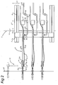
- Figure 2 shows a plan view of the hydrocarbon transfer system of fig. 1 .
- the parts of the hydrocarbon transfer system 1 shown with dotted lines have the position of the connection member 22 when the vertical duct part 20 is pivoted around the second axis 16 upon movement of the structure 23 in the length direction 3.
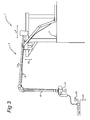
- Figure 3 shows a vertical flexible hose part 60 for the transfer of cryogenic fluid which is connected to the transverse arm 12a.
- the vertical flexible hose 60 part can be combined with a rigid support arm (not shown) extending downwardly and alongside the vertical hose from the transverse arm 12a.
Landscapes
- Engineering & Computer Science (AREA)
- Mechanical Engineering (AREA)
- Chemical & Material Sciences (AREA)
- Combustion & Propulsion (AREA)
- Ocean & Marine Engineering (AREA)
- Loading And Unloading Of Fuel Tanks Or Ships (AREA)
Claims (10)
- Système de transfert d'hydrocarbures (1) comprenant une première structure (2) ayant un sens de la longueur (3), un sens de la largeur (4) et un niveau de pont (11), une structure de support (10) s'étendant vers le haut depuis le niveau de pont (11) de la première structure et supportant une piste (8) s'étendant dans le sens transversal (4), une partie de cadre mobile (7) étant raccordée à la piste (8), un élément sensiblement transversal (12a) et un élément vertical (13,60) étant fixés à la partie de cadre mobile (7), un élément vertical s'étendant vers le bas depuis une première extrémité de l'élément transversal (12a) depuis une articulation mobile (14), de façon à pouvoir pivoter autour d'un premier axe (15) s'étendant dans le sens de la longueur (3) et un second axe (16) s'étendant dans le sens transversal (4), caractérisé en ce que- le niveau de pont (11) est situé au dessus du niveau de la mer,- l'élément transversal (12a) comprenant un conduit de transfert de fluide rigide,- un élément vertical (13, 60) comprend un conduit de transfert de fluide, dans lequel- une seconde extrémité du conduit transversal (12a) est fixée à un conduit de transfert de fluide interne (52) sur la première structure située plus près du niveau du pont (12) que le conduit transversal (12a), via un élément de transfert de fluide à ajustement de longueur (50, 51) qui peut être déplacé horizontalement lors du mouvement de la seconde extrémité du conduit transversal (12a) relativement au conduit de transfert de fluide interne (52).
- Système de transfert d'hydrocarbures (1) selon la revendication 1, dans lequel l'élément de transfert de fluide à ajustement de longueur (50, 51) comprend un premier conduit (50) ayant une première extrémité fixée au conduit transversal (12a) via un premier pivot (26), un second conduit (51) fixé avec une première extrémité à la seconde extrémité du premier conduit (50) via un deuxième pivot (54) et fixé avec une seconde extrémité au conduit interne (52) via un troisième pivot (55), le premier, le deuxième et le troisième pivots (26, 54, 55) tournant chacun autour d'un axe qui s'étend dans le sens de la longueur (3).
- Système de transfert d'hydrocarbures (1) selon la revendication 1, dans lequel la piste (8) se projette au delà d'un périmètre (9) de la première structure (2).
- Système de transfert d'hydrocarbures selon l'une quelconque des revendications 2 ou 3, dans lequel le conduit de transfert de fluide (6) est raccordé à un élément de stockage/traitement ou de transfert sur la première structure via un raccord qui peut s'adapter au mouvement.
- Système de transfert d'hydrocarbures selon l'une quelconque des revendications précédentes, dans lequel la première structure (2) comprend une direction en hauteur (24) et la partie de cadre mobile (7) peut être déplacée dans le sens de la hauteur (24).
- Système de transfert d'hydrocarbures selon les revendications 1, 2, 3 ou 4, le conduit vertical (13) étant raccordé à l'articulation (14) de façon à pivoter autour d'un premier axe (15) s'étendant dans le sens de la longueur (3) et un second axe (16) s'étendant dans le sens transversal (4).
- Système de transfert d'hydrocarbures selon la revendication 6, dans lequel le bras transversal ou conduit (12) est raccordé en pivotement à la partie de cadre mobile (7) et un contrepoids (17) est relié à ou près d'une extrémité du bras transversal ou conduit (12).
- Système de transfert d'hydrocarbures selon les revendications 6 ou 7, comprenant un actionneur (18) sur la partie de cadre mobile (7) pour faire pivoter le bras transversal ou conduit (12).
- Système de transfert d'hydrocarbures selon la revendication 6-8, dans lequel la partie du conduit de transfert vertical (13) comprend un tuyau flexible.
- Système de transfert d'hydrocarbures selon les revendications 6-8, dans lequel la partie du conduit de transfert vertical comprend un bras de transfert de fluide rigide (20) qui est relié au bras transversal ou conduit (12), par le biais d'un pivot de transfert de fluide (21) permettant une rotation autour de l'axe (15) s'étendant dans le sens de la longueur et d'un axe (16) s'étendant dans le sens transversal.
Priority Applications (1)
| Application Number | Priority Date | Filing Date | Title |
|---|---|---|---|
| EP20070727488 EP1999008B1 (fr) | 2006-03-30 | 2007-03-29 | Système de transfert d'hydrocarbures à déplacement horizontal |
Applications Claiming Priority (3)
| Application Number | Priority Date | Filing Date | Title |
|---|---|---|---|
| EP06112025 | 2006-03-30 | ||
| EP20070727488 EP1999008B1 (fr) | 2006-03-30 | 2007-03-29 | Système de transfert d'hydrocarbures à déplacement horizontal |
| PCT/EP2007/053016 WO2007113201A1 (fr) | 2006-03-30 | 2007-03-29 | Système de transfert d'hydrocarbures à déplacement horizontal |
Publications (2)
| Publication Number | Publication Date |
|---|---|
| EP1999008A1 EP1999008A1 (fr) | 2008-12-10 |
| EP1999008B1 true EP1999008B1 (fr) | 2010-02-24 |
Family
ID=36931589
Family Applications (1)
| Application Number | Title | Priority Date | Filing Date |
|---|---|---|---|
| EP20070727488 Expired - Fee Related EP1999008B1 (fr) | 2006-03-30 | 2007-03-29 | Système de transfert d'hydrocarbures à déplacement horizontal |
Country Status (3)
| Country | Link |
|---|---|
| US (1) | US8176938B2 (fr) |
| EP (1) | EP1999008B1 (fr) |
| WO (1) | WO2007113201A1 (fr) |
Families Citing this family (16)
| Publication number | Priority date | Publication date | Assignee | Title |
|---|---|---|---|---|
| FR2927322B1 (fr) * | 2008-02-08 | 2010-03-05 | Fmc Technologies Sa | Dispositif de commande directe, notamment proportionnelle et/ou de chargement et/ou dechargement de fluides |
| FR2931451B1 (fr) * | 2008-05-22 | 2010-12-17 | Fmc Technologies Sa | Dispositif de commande pour systeme de chargement et/ou dechargement de fluides |
| NL2001758C2 (nl) * | 2008-07-04 | 2010-01-05 | Zwijnenberg Evert Hendrik Will | Hulpinrichting voor plaatsing tussen een trek- of duwkracht verschaffend eerste object en een tweede object waarop de trek- of duwkracht wordt uitgeoefend. |
| KR101069659B1 (ko) | 2008-11-11 | 2011-10-04 | 삼성중공업 주식회사 | 액화천연가스 이송장치 |
| KR101159190B1 (ko) * | 2009-10-30 | 2012-07-10 | 삼성중공업 주식회사 | 선박용 로딩 암 구조체 및 이를 포함하는 선박 |
| EP2773555B1 (fr) * | 2011-11-03 | 2017-01-18 | Shell Internationale Research Maatschappij B.V. | Manipulateur de tuyau de transfert de fluides et procédé de transfert de fluides |
| US8915271B2 (en) | 2011-12-20 | 2014-12-23 | Xuejie Liu | System and method for fluids transfer between ship and storage tank |
| CA2909192C (fr) * | 2012-05-25 | 2020-06-02 | T&T Engineering Services, Inc. | Systeme de transport et de mise en uvre de conduite de branchement |
| DE102012212916A1 (de) * | 2012-07-24 | 2014-01-30 | Putzmeister Engineering Gmbh | Rundverteiler für Dickstoffe |
| NO340699B1 (no) * | 2013-02-05 | 2017-06-06 | Macgregor Norway As | Fluidoverføringssystem, samt fremgangsmåte, for overføring av kryogenisk hydrokarbonbasert fluid fra en forsyningsstruktur til en mottaksstruktur |
| FR3003855B1 (fr) * | 2013-03-29 | 2016-01-29 | Fmc Technologies Sa | Bras de transfert d'un produit fluide de navire a navire |
| FR3018766B1 (fr) * | 2014-03-24 | 2016-04-01 | Gaztransp Et Technigaz | Systeme pour le transfert de fluide entre navire et une installation, telle qu'un navire client |
| US10358338B2 (en) | 2016-04-02 | 2019-07-23 | Xuejie Liu | Auto-balancing hose system and method for fluid transfer |
| GB2550332B (en) * | 2016-05-11 | 2020-04-15 | Klaw Products Ltd | Method of arranging a vessel assembly comprising first and second vessels interconnected via a flexible conduit |
| US11346497B2 (en) * | 2020-09-14 | 2022-05-31 | Christopher Rixon Irvine | Grease gun extension device |
| FR3123340B1 (fr) * | 2021-05-28 | 2023-12-08 | Air Liquide | Installation de transfert de fluide |
Family Cites Families (10)
| Publication number | Priority date | Publication date | Assignee | Title |
|---|---|---|---|---|
| CA1099186A (fr) * | 1978-04-08 | 1981-04-14 | George Fujita | Traduction non-disponible |
| US4393906A (en) * | 1979-10-01 | 1983-07-19 | Fmc Corporation | Stern to bow offshore loading system |
| EP0167642B1 (fr) * | 1984-07-04 | 1988-03-30 | von Meyerinck, Wolfgang, Dipl.-Ing. | Bras pour ravitaillement en carburant |
| US4987925A (en) * | 1989-09-29 | 1991-01-29 | Ltv Energy Products | Loading arm with a lock-down device |
| GB2361459A (en) | 2000-04-20 | 2001-10-24 | Bluewater Terminal Systems Nv | Floating vessel with pipeline attachment apparatus |
| FR2813872B1 (fr) * | 2000-09-14 | 2003-01-31 | Fmc Europe | Ensemble a bras articule de chargement et de dechargement de produits, en particulier de produits fluides |
| GB2367049A (en) | 2000-09-21 | 2002-03-27 | Ocean Technologies Ltd | Ship to ship LNG transfer system |
| US6829901B2 (en) | 2001-12-12 | 2004-12-14 | Exxonmobil Upstream Research Company | Single point mooring regasification tower |
| GB2391838A (en) | 2002-08-13 | 2004-02-18 | Bluewater Terminal Systems Nv | Fluid transfer interface with a floating vessel |
| JP5128938B2 (ja) | 2004-04-29 | 2013-01-23 | シングル・ブイ・ムーリングス・インコーポレイテッド | サイド・バイ・サイドの炭化水素移送システム |
-
2007
- 2007-03-29 US US12/295,440 patent/US8176938B2/en not_active Expired - Fee Related
- 2007-03-29 EP EP20070727488 patent/EP1999008B1/fr not_active Expired - Fee Related
- 2007-03-29 WO PCT/EP2007/053016 patent/WO2007113201A1/fr not_active Ceased
Also Published As
| Publication number | Publication date |
|---|---|
| US8176938B2 (en) | 2012-05-15 |
| EP1999008A1 (fr) | 2008-12-10 |
| US20100243075A1 (en) | 2010-09-30 |
| WO2007113201A1 (fr) | 2007-10-11 |
Similar Documents
| Publication | Publication Date | Title |
|---|---|---|
| US8176938B2 (en) | Hydrocarbon transfer system with horizontal displacement | |
| EP1999009B1 (fr) | Systeme de transfert d'hydrocarbures avec axe de rotation vertical | |
| US7066219B2 (en) | Hydrocarbon fluid transfer system | |
| CA2469688C (fr) | Systeme de debarquement de gnl au mouillage | |
| CN1946606B (zh) | 并列式碳氢化合物转移系统 | |
| EP1428748B1 (fr) | Système d'amarrage et de transfert de fluide offshore | |
| KR100939582B1 (ko) | 유체물 특히 액화 천연가스를 선박과 같은 운송수단과 상기 유체물의 수용 혹은 공급 시설물 사이에 이송하는 시스템 | |
| KR20140092875A (ko) | 유체 전달 호스 조작기 및 유체 전달 방법 | |
| GB2040849A (en) | Mooring system | |
| KR102759927B1 (ko) | 유체 제품의 전달 시스템 | |
| RU2359859C2 (ru) | Устройство для передачи текучей среды в открытом море | |
| CA3083322A1 (fr) | Dispositif de transfert de produits cryogeniques entre une structure flottante et une structure fixe ou flottante | |
| EP1575825B1 (fr) | Systeme et procede de transfert de fluide | |
| WO2001062582A2 (fr) | Chargement en mer d'hydrocarbures vers le bras saillant d'un navire |
Legal Events
| Date | Code | Title | Description |
|---|---|---|---|
| PUAI | Public reference made under article 153(3) epc to a published international application that has entered the european phase |
Free format text: ORIGINAL CODE: 0009012 |
|
| 17P | Request for examination filed |
Effective date: 20081001 |
|
| AK | Designated contracting states |
Kind code of ref document: A1 Designated state(s): FR |
|
| DAX | Request for extension of the european patent (deleted) | ||
| RBV | Designated contracting states (corrected) |
Designated state(s): FR |
|
| GRAP | Despatch of communication of intention to grant a patent |
Free format text: ORIGINAL CODE: EPIDOSNIGR1 |
|
| GRAS | Grant fee paid |
Free format text: ORIGINAL CODE: EPIDOSNIGR3 |
|
| GRAA | (expected) grant |
Free format text: ORIGINAL CODE: 0009210 |
|
| AK | Designated contracting states |
Kind code of ref document: B1 Designated state(s): FR |
|
| PLBE | No opposition filed within time limit |
Free format text: ORIGINAL CODE: 0009261 |
|
| STAA | Information on the status of an ep patent application or granted ep patent |
Free format text: STATUS: NO OPPOSITION FILED WITHIN TIME LIMIT |
|
| 26N | No opposition filed |
Effective date: 20101125 |
|
| REG | Reference to a national code |
Ref country code: FR Ref legal event code: PLFP Year of fee payment: 9 |
|
| PGFP | Annual fee paid to national office [announced via postgrant information from national office to epo] |
Ref country code: FR Payment date: 20150331 Year of fee payment: 9 |
|
| REG | Reference to a national code |
Ref country code: FR Ref legal event code: ST Effective date: 20161130 |
|
| PG25 | Lapsed in a contracting state [announced via postgrant information from national office to epo] |
Ref country code: FR Free format text: LAPSE BECAUSE OF NON-PAYMENT OF DUE FEES Effective date: 20160331 |
|
| P01 | Opt-out of the competence of the unified patent court (upc) registered |
Effective date: 20230525 |