EP1999367B1 - Injecteur variable chauffe par induction - Google Patents
Injecteur variable chauffe par induction Download PDFInfo
- Publication number
- EP1999367B1 EP1999367B1 EP07753413.9A EP07753413A EP1999367B1 EP 1999367 B1 EP1999367 B1 EP 1999367B1 EP 07753413 A EP07753413 A EP 07753413A EP 1999367 B1 EP1999367 B1 EP 1999367B1
- Authority
- EP
- European Patent Office
- Prior art keywords
- fuel
- injector
- heating coil
- coil
- armature
- Prior art date
- Legal status (The legal status is an assumption and is not a legal conclusion. Google has not performed a legal analysis and makes no representation as to the accuracy of the status listed.)
- Active
Links
Images

Classifications
-
- F—MECHANICAL ENGINEERING; LIGHTING; HEATING; WEAPONS; BLASTING
- F02—COMBUSTION ENGINES; HOT-GAS OR COMBUSTION-PRODUCT ENGINE PLANTS
- F02M—SUPPLYING COMBUSTION ENGINES IN GENERAL WITH COMBUSTIBLE MIXTURES OR CONSTITUENTS THEREOF
- F02M53/00—Fuel-injection apparatus characterised by having heating, cooling or thermally-insulating means
- F02M53/04—Injectors with heating, cooling, or thermally-insulating means
- F02M53/06—Injectors with heating, cooling, or thermally-insulating means with fuel-heating means, e.g. for vaporising
-
- F—MECHANICAL ENGINEERING; LIGHTING; HEATING; WEAPONS; BLASTING
- F02—COMBUSTION ENGINES; HOT-GAS OR COMBUSTION-PRODUCT ENGINE PLANTS
- F02M—SUPPLYING COMBUSTION ENGINES IN GENERAL WITH COMBUSTIBLE MIXTURES OR CONSTITUENTS THEREOF
- F02M51/00—Fuel-injection apparatus characterised by being operated electrically
- F02M51/06—Injectors peculiar thereto with means directly operating the valve needle
- F02M51/061—Injectors peculiar thereto with means directly operating the valve needle using electromagnetic operating means
- F02M51/0625—Injectors peculiar thereto with means directly operating the valve needle using electromagnetic operating means characterised by arrangement of mobile armatures
- F02M51/0664—Injectors peculiar thereto with means directly operating the valve needle using electromagnetic operating means characterised by arrangement of mobile armatures having a cylindrically or partly cylindrically shaped armature, e.g. entering the winding; having a plate-shaped or undulated armature entering the winding
- F02M51/0671—Injectors peculiar thereto with means directly operating the valve needle using electromagnetic operating means characterised by arrangement of mobile armatures having a cylindrically or partly cylindrically shaped armature, e.g. entering the winding; having a plate-shaped or undulated armature entering the winding the armature having an elongated valve body attached thereto
-
- F—MECHANICAL ENGINEERING; LIGHTING; HEATING; WEAPONS; BLASTING
- F02—COMBUSTION ENGINES; HOT-GAS OR COMBUSTION-PRODUCT ENGINE PLANTS
- F02M—SUPPLYING COMBUSTION ENGINES IN GENERAL WITH COMBUSTIBLE MIXTURES OR CONSTITUENTS THEREOF
- F02M61/00—Fuel-injectors not provided for in groups F02M39/00 - F02M57/00 or F02M67/00
- F02M61/16—Details not provided for in, or of interest apart from, the apparatus of groups F02M61/02 - F02M61/14
- F02M61/18—Injection nozzles, e.g. having valve seats; Details of valve member seated ends, not otherwise provided for
- F02M61/188—Spherical or partly spherical shaped valve member ends
Definitions
- This invention relates to automotive fuel injection and, more particularly, to inductive heating in a fuel injector.
- HC hydrocarbon
- CO carbon monoxide
- NOx nitrogen oxide
- catalytic converter is placed within the exhaust gas stream between the exhaust manifold of the engine and the muffler of a vehicle.
- a large percentage of a vehicles total cold start HC emissions occur during the time period while the catalytic converter is warming-up to operating temperature.
- JP 2002180919 A discloses an electromagnetic coil for valve opening provided in a valve housing, an electromagnetic coil for heating power source connected by electromagnetic induction to this electromagnetic coil for valve opening.
- a resistor is connected to the electromagnetic coil for heating power source through a lead wire.
- a movable core is actuated by carrying a prescribed drive current to the electromagnetic coil for valve opening, to hold a needle valve in an opened condition, heated fuel from a fuel passage is jetted into an intake manifold from an injection port.
- a high frequency alternating current of frequency or a current value to a degree of not opening the needle valve is applied to the electromagnetic coil for valve opening after the drive current is interrupted, a current is generated in the electromagnetic coil for heating power source by electromagnetic induction action, the resistor is heated through the lead wire, fuel is directly heated.
- US 6176226 B1 discloses a method and apparatus for controlling a heated tip injector having a connector with more than two pins.
- the method includes (a) providing a plurality of heated tip injectors each having a coil and an internal heater; (b) maintaining all the internal heaters in an OFF state while the engine is cranking; (c) maintaining an internal beater in an OFF state if any of the coils are ON; and (d) maintaining an internal heater in an ON state if the engine is not cranking and all the internal heater coils are OFF.
- One embodiment of the apparatus includes a plurality of heated tip injectors each having a coil and an internal heater; a power supply; an ignition switch connected to the power supply, one end of each coil and heater being connected together and to the ignition switch; an engine electronic control unit, another end of each coil being connected to the engine electronic control unit; means for switching each internal heater ON and OFF, another end of each internal heater being connected through a respective means for switching to ground; a crank circuit including a crank for cranking the engine; and means for isolating the crank circuit from the engine electronic control unit.
- the magnet coil or heat-conducting coil support disclosed in DE 19629589 A1 are thermally coupled to a coil-enclosed heat exchange sector of the fuel feed channel.
- the coil support tightly encloses the heat exchange sector by a metal sleeve wound with the magnetic coil.
- One end of this sleeve has a shoulder radiating to a sleeve axis so as to axially demarcate the coil together with a sleeve-mounted ring.
- the heat exchange sector is walled in heat-conducting material.
- a Peltier element as heat pump should be interposed between coil and sector and has a first surface which heats up when the element is operating. It faces the heat exchange sector compared with a second surface which faces the magnetic coil and necessarily cools as the first surface heats up.
- the Peltier element takes the form of two half shells forming a hollow cylinder.
- US 5159915 A relates to a fuel injector for injecting a heated fuel into a combustion engine which comprises an electro-magnetic coil for generating a fluctuating magnetic flux density, a fuel heating member in which the fluctuating magnetic flux density is generated by the electro-magnetic coil so that the fuel heating member is heated by the fluctuating magnetic flux density and a heat energy of the fuel heating member generated by the fluctuating magnetic flux density is transmitted to the fuel to supply the heated fuel, and a fuel path member in which the fuel flows to be injected from the fuel injector into the combustion engine and in which the fuel heating member is arranged to heat the fuel, wherein a magnetic permeability of the fuel heating member is larger than that of the fuel path member so that a magnetic flux density in the fuel heating member is larger than a magnetic flux density in the fuel path member.
- the fuel injector includes a valve body with a valve seat associated with the valve body.
- the valve seat defines an outlet opening through which fuel may flow.
- An armature is associated with the valve body and is movable with respect to the valve body between a first position and a second position.
- the armature is associated with a closure member proximate the outlet opening and contiguous to the valve seat when in the first position, and spaced from the valve seat when in the second position.
- An electromagnetic coil is energizable to provide magnetic flux that moves the armature between the first and second positions to control liquid fuel flow through the outlet opening.
- a heating coil is energizable to provide heat and thereby vaporize liquid fuel as it exits the outlet opening.
- the valve body includes a tube portion and the armature is disposed in the tube portion.
- the armature is a sealed hollow tube with a periphery thereof being constructed and arranged to direct fuel there-around.
- a fuel passage is defined between an outer periphery of the armature and an inside of the tube portion, the heating coil, for vaporizing liquid fuel as it exits the outlet opening, is disposed about the tube portion and energizable so as to heat fuel in the fuel passage by means of heating a wall of the valve body and by using AC current for inductively heating a portion of the armature.
- the fuel injector further comprises a capacitor electrically connected between the electromagnetic coil and the heating coil.
- the electromagnetic coil is constructed and arranged to receive pulse width direct current modulation and the heating coil is constructed and arranged to receive alternating current in the same circuit.
- a method of vaporizing fuel as it exits a fuel injector of an internal combustion engine provides a fuel injector having heating structure constructed and arranged to heat liquid fuel.
- the liquid fuel is heated with the heating structure to vaporize the liquid fuel as it exits the fuel injector.
- a solenoid actuated fuel injector which can be of the so-called top feed type, supplies fuel to an internal combustion engine (not shown).
- the fuel injector 10 includes a valve body 14 extending along a longitudinal axis A.
- the valve body 14 includes a valve seat 18 defining a seating surface 22, which can have a frustoconical or concave shape, facing the interior of the valve body 14.
- the seating surface 22 includes a fuel outlet opening 24 centered on the axis A and in communication with an inlet tube 26 for conducting pressurized fuel into the valve body 14 against the seating surface 22.
- the inlet tube 26 defines an inlet end 15 of the injector 10 and has a retainer 30 for mounting the fuel injector 10 in a fuel rail (not shown) as is known.
- An O-ring 32 is used to seal the inlet end 15 in the fuel rail.
- a closure member, e.g., a spherical valve ball 34, within the injector 10 is moveable between a first, seated, i.e., closed, position and a second, open position.
- a closure member e.g., a spherical valve ball 34
- the ball 34 In the closed position, the ball 34 is urged against the seating surface 22 to close the outlet opening 24 against fuel flow.
- the ball 34 In the open position, the ball 34 is spaced from the seating surface 22 to allow fuel flow through the outlet opening 24.
- An armature 38 that is axially moveable along axis A in a tube portion 39 of the valve body 14 includes valve ball capturing means 40 at an end proximate the seating surface 22.
- the valve ball capturing means 40 engages with the valve ball 34 outer surface adjacent the seating surface 22 and so that the valve ball 34 rests on the seating surface 22 in the closed position of the valve ball 34.
- a spring 36 biases the armature 38 and thus the valve ball 34 toward the closed position.
- the fuel injector 10 may be calibrated by positioning adjustment tube 37 axially within inlet tube 26 to preload spring 36 to a desired bias force.
- a filter 39 is provided within the tube 37 to filter fuel.
- the valve body 14, armature 38, valve seat 18 and valve ball 34 define a valve group assembly such as disclosed in U.S. Patent No. 6,685,112 B1 .
- the electromagnetic coil 44 surrounds a pole piece or stator 47 formed of a ferromagnetic material.
- the electromagnetic coil 44 is operable, in the conventional manner, to produce magnetic flux to draw the armature 38 away from the seating surface 22, thereby moving the valve ball 34 to the open position and allowing fuel to pass through the fuel outlet opening 24. Deactivation of the electromagnetic coil 44 allows the spring 36 to return the valve ball 34 to the closed position against the seating surface 22 and to align itself in the closed position, thereby closing the outlet opening 24 against the passage of fuel.
- the electromagnetic coil is DC operated.
- the coil 44 with bobbin, and stator 47 are preferably over-molded to define a power or coil subassembly such has disclosed in U.S. Patent No. 6,685,112 B1 .
- a non-magnetic sleeve 46 is pressed onto one end of the inlet tube 26 and the sleeve 46 and inlet tube 26 are welded together to provide a first hermetic joint therebetween.
- the sleeve 46 and inlet tube 26 are then pressed into the valve body 14, and the sleeve 46 and valve body 14 are welded together to provide a second hermetic joint therebetween.
- the fuel passage 41 is defined inside the valve body 14 such that fuel introduced into the inlet end 15 passes over the valve ball 34 and through the outlet opening 24 when the valve ball 24 is in the open position.
- a heating coil 50 is disposed about the tube portion 39 of the valve body 14 and is energizable to provide heat and to thereby vaporize liquid fuel.
- the heating coil 50 atomizes fuel using inductive heating in the injector 10 where the liquid fuel is vaporized as it exits the outlet opening 24 for use during the cold start phase.
- Vaporized fuel will readily mix with the inlet air to enable a much reduced HC emission cold start. This is accomplished through the ability to more efficiently control the ignition and combustion properties during the cold start to promote rapid catalyst warm-up while maintaining operator drivability.
- a benefit is the ability to enable an open inlet valve injection strategy with reduced transient fueling issues.
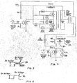
- FIG. 2 A circuit for diving the injector 10 and the heating coil 50 is shown in FIG. 2 .
- a capacitor 52 is electrically connected between the electromagnetic coil 44 and the heating coil 50 so as to separate the coil 44 from coil 50.
- a space 54 is provided between the electromagnetic coil 44 and the heating coil 50 to accommodate the capacitor 52 (not shown in FIG. 1 ).
- the heating coil 50 operates on alternating current (AC).
- AC alternating current
- only two wires are required to connect the injector 10 to the Engine Control Unit (including the injector driver 55) and to the heater driver 57.
- a two wire electrical connector 48 is used to power the injector 10.
- the frequency of the heater driver is preferably 40 kHz.
- a voltage waveform 56 is shown in FIG. 3 , when the heating coil 50 of the fuel injector 10 is on, and the voltage waveform 56 is shown in FIG. 4 when the heating coil 50 is off.
- the electromagnetic coil 44 uses the conventional pulse width DC modulation to open and close the injector 10.
- the heating coil 50 uses AC current to inductively heat an portion of the armature 38.
- the heating coil 50 is a two layer winding with 22 gage square wire and 50 turns. The AC to the heating coil 50 can be turned on or off based on when vapor is needed.
- the heating coil 50 and the electromagnetic coil 44 are preferably provided as a unit for ease in assembly.
- the heating coil surrounds the valve body 14.
- a wall of the valve body is made thin enough so as to be heated by the coil 50.
- the fuel passage 41 is provided between an inside of the tube portion 39 of the valve body 14 and the outer periphery of the armature 38 so as to quickly heat the fuel.
- the armature 38 is of hollow tube shape and is constructed and arranged to direct the fuel around the outside of the tube. Since the armature 38 is a hollow tube, it is light-weight and has a reduced heat mass so it can also heat quickly.
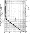
- FIG. 5 is a graph of a test of the heater driver 57 showing that vapor occurs rapidly (e.g., in 0.7 seconds) when the heating coil 50 is turned on.
- the particle size measured 32 microns Sauter Mean Diameter (SMD) during heating of the fuel using the heating coil 50. This measurement was taken at 50 mm from the tip of the injector instead of the traditional 100 mm.
- the injector 10 can be used in alcohol and gasoline, and flex fuel applications.
- the injector 10 with heating coil 50 enables lower cold start HC emissions. Lean operation with stable combustion is achieved during the cold warm-up phase.
- the injector 10 may be operated with retarded spark timing as a heat source for faster catalyst light-off.
- the injector 10 offers a system with minor modifications to customers engines. With the injector 10, an increase of system LR can be achieved due to operation on vapor at low demand conditions.
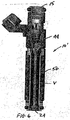
- FIG. 6 another embodiment of an injector 10' is shown.
- the injector 10' is substantially similar to the injector 10 of FIG. 1 , except that injector 10' has an increased fuel heating volume V.
- the heating volume is increased from 0.1cc ( FIG. 1 ) to 0.9cc ( FIG. 6 ).
- the injector 10' can be used for Flex Fuel Start applications to reduce emissions when E100 and E85 are the fuels used.
- the injector 10' enables efficient vehicle starts with E100 down to temperatures of -5C with 200 W heating power even if flash boiling is interrupted. In conventional E100 applications, a vehicle will not start at 20 C and these applications require an additional gasoline tank as a start system.
- the injector 10, 10' in E85 applications, the oil dilution is reduced by 2.5 times and the start emissions are significantly reduced and are equal to that of a gasoline application.
- the injector 10' enables efficient vehicle starts with E85 down to temperatures of -30 C.
Landscapes
- Engineering & Computer Science (AREA)
- Chemical & Material Sciences (AREA)
- Combustion & Propulsion (AREA)
- Mechanical Engineering (AREA)
- General Engineering & Computer Science (AREA)
- Physics & Mathematics (AREA)
- Electromagnetism (AREA)
- Fuel-Injection Apparatus (AREA)
- Magnetically Actuated Valves (AREA)
Claims (9)
- Injecteur (10, 10') de carburant pour moteur à combustion interne, comprenant :un corps (14) de soupape ;un siège (18) de soupape associé au corps (14) de soupape, le siège (18) de soupape délimitant une ouverture (24) de sortie par laquelle le carburant peut s'écouler ;un induit (38) associé au corps (14) de soupape et mobile par rapport à celui-ci entre une première position et une seconde position, l'induit (38) étant associé à un élément (34) de fermeture situé à proximité de l'ouverture (24) de sortie, contigu au siège (18) de soupape quand il est dans la première position et espacé du siège (18) de soupape quand il est dans la seconde position ;une bobine électromagnétique (44) pouvant être alimentée pour créer un flux magnétique qui déplace l'induit (38) entre les première et seconde positions pour commander l'écoulement de carburant liquide par l'ouverture (24) de sortie ;une bobine de chauffage (50),caractérisé par un condensateur (52),
dans lequel :l'induit (38) est un tube creux scellé dont la périphérie est construite et agencée pour diriger le carburant autour d'elle ;le condensateur (52) est raccordé électriquement entre la bobine électromagnétique (44) et la bobine de chauffage (50) et sépare la bobine électromagnétique (44) et la bobine de chauffage (50), la bobine électromagnétique (44) étant construite et agencée pour recevoir une modulation d'impulsions en durée de courant continu et la bobine de chauffage (50) étant construite et agencée pour recevoir du courant alternatif sur le même circuit ;le corps (14) de soupape comprend une partie de tube (39) et l'induit (38) est disposé dans la partie de tube (39), un passage (41) de carburant est délimité entre la périphérie extérieure de l'induit (38) et l'intérieur de la partie de tube (39), la bobine de chauffage, pour vaporiser le carburant liquide quand il sort de l'ouverture (24) de sortie, est disposée autour de la partie de tube (39) et peut être alimentée de façon à chauffer le carburant dans le passage (41) de carburant par chauffage de la paroi du corps (14) de soupape et en utilisant un courant alternatif pour chauffer par induction une partie de l'induit (38). - Injecteur (10, 10') de carburant selon la revendication 1, dans lequel seuls deux fils sont utilisés pour alimenter l'injecteur.
- Injecteur (10, 10') de carburant selon la revendication 2, en combinaison avec un circuit de sortie (57) d'élément thermique pour piloter la bobine de chauffage (50) et un circuit de sortie (55) d'injecteur pour piloter la bobine électromagnétique (44).
- Injecteur (10, 10') de carburant selon la revendication 3, dans lequel le circuit de sortie (57) d'élément thermique fonctionne à une fréquence de 40 kHz.
- Injecteur (10, 10') de carburant selon la revendication 1, dans lequel la bobine électromagnétique (44) et la bobine de chauffage (50) définissent une unité.
- Injecteur (10, 10') de carburant selon la revendication 1, dans lequel la bobine de chauffage (50) est un enroulement à deux couches avec 50 spires de fil carré de calibre 22.
- Injecteur (10, 10') de carburant selon la revendication 1, dans lequel la bobine de chauffage (50) comprend une bobine et un entrefer est disposé entre la bobine de chauffage (50) et la partie de tube (39) du corps (14) de soupape.
- Injecteur (10, 10') de carburant selon la revendication 1, dans lequel le carburant est du E85.
- Injecteur (10, 10') de carburant selon la revendication 1, dans lequel le carburant est du E100.
Applications Claiming Priority (3)
| Application Number | Priority Date | Filing Date | Title |
|---|---|---|---|
| US78321906P | 2006-03-17 | 2006-03-17 | |
| US11/723,050 US7481376B2 (en) | 2006-03-17 | 2007-03-16 | Variable inductive heated injector |
| PCT/US2007/006782 WO2007109219A2 (fr) | 2006-03-17 | 2007-03-19 | Injecteur variable chauffe par induction |
Publications (2)
| Publication Number | Publication Date |
|---|---|
| EP1999367A2 EP1999367A2 (fr) | 2008-12-10 |
| EP1999367B1 true EP1999367B1 (fr) | 2019-05-08 |
Family
ID=38442595
Family Applications (1)
| Application Number | Title | Priority Date | Filing Date |
|---|---|---|---|
| EP07753413.9A Active EP1999367B1 (fr) | 2006-03-17 | 2007-03-19 | Injecteur variable chauffe par induction |
Country Status (4)
| Country | Link |
|---|---|
| US (1) | US7481376B2 (fr) |
| EP (1) | EP1999367B1 (fr) |
| JP (1) | JP5091224B2 (fr) |
| WO (1) | WO2007109219A2 (fr) |
Families Citing this family (26)
| Publication number | Priority date | Publication date | Assignee | Title |
|---|---|---|---|---|
| EP1999366A1 (fr) * | 2006-03-21 | 2008-12-10 | Continental Automotive Systems Us, Inc. | Injecteur de carburant avec chauffage inductif |
| US8967124B2 (en) * | 2006-03-21 | 2015-03-03 | Continental Automotive Systems, Inc. | Inductive heated injector using voltage transformer technology |
| US8695901B2 (en) * | 2006-03-22 | 2014-04-15 | Continental Automotive Systems, Inc. | Inductive heated injector using a three wire connection |
| US20070221747A1 (en) * | 2006-03-22 | 2007-09-27 | Siemens Vdo Automotive Corporation | Super imposed signal for an actuator and heater of a fuel injector |
| US7798131B2 (en) * | 2007-03-16 | 2010-09-21 | Continental Automotive Systems Us, Inc. | Automotive modular inductive heated injector and system |
| US7905219B2 (en) * | 2007-08-24 | 2011-03-15 | Continental Automotive Gmbh | Method and apparatus for heating at least one injector of an engine |
| US20090107473A1 (en) * | 2007-10-26 | 2009-04-30 | Continental Automotive Systems Us, Inc. | Cold start structure for multipoint fuel injection systems |
| US7681558B2 (en) * | 2008-01-15 | 2010-03-23 | Ford Global Technologies, Llc | System and method to control fuel vaporization |
| US20100252653A1 (en) * | 2008-05-30 | 2010-10-07 | Delphi Technologies, Inc. | Heated fuel injector |
| US20100078507A1 (en) * | 2008-09-29 | 2010-04-01 | Short Jason C | Heated and insulated fuel injector |
| US20100126471A1 (en) * | 2008-11-25 | 2010-05-27 | Cheiky Michael C | Dual solenoid fuel injector with catalytic activator section |
| US8342425B2 (en) * | 2008-12-03 | 2013-01-01 | Continental Automotive Systems Us, Inc. | Multi-point low pressure inductively heated fuel injector with heat exchanger |
| US7866301B2 (en) * | 2009-01-26 | 2011-01-11 | Caterpillar Inc. | Self-guided armature in single pole solenoid actuator assembly and fuel injector using same |
| US8694230B2 (en) * | 2009-05-19 | 2014-04-08 | Sturman Digital Systems, Llc | Fuel systems and methods for cold environments |
| US8884198B2 (en) * | 2010-01-22 | 2014-11-11 | Continental Automotive Systems, Inc. | Parametric temperature regulation of induction heated load |
| US9074566B2 (en) * | 2011-04-22 | 2015-07-07 | Continental Automotive Systems, Inc. | Variable spray injector with nucleate boiling heat exchanger |
| US8624684B2 (en) * | 2011-04-22 | 2014-01-07 | Continental Automotive Systems, Inc | Adaptive current limit oscillator starter |
| DE102011085680B4 (de) * | 2011-11-03 | 2013-07-04 | Continental Automotive Gmbh | Heizspule für ein Einspritzventil und Einspritzventil |
| US20130275025A1 (en) * | 2012-04-11 | 2013-10-17 | Delphi Technologies, Inc. | System and method for controlling a heated fuel injector in an internal combustion engine |
| US9784227B2 (en) * | 2012-07-25 | 2017-10-10 | Toyota Jidosha Kabushiki Kaisha | Fuel injection system |
| DE102013102219B4 (de) * | 2013-03-06 | 2020-08-06 | Dr. Ing. H.C. F. Porsche Aktiengesellschaft | Beheizbarer Injektor zur Kraftstoffeinspritzung bei einer Brennkraftmaschine |
| US8997463B2 (en) | 2013-04-17 | 2015-04-07 | Continental Automotive Systems, Inc. | Reductant delivery unit for automotive selective catalytic reduction with reducing agent heating |
| US20150109084A1 (en) * | 2013-10-17 | 2015-04-23 | Intellitronix Corporation | Automobile Ignition with Improved Coil Configuration |
| WO2017084901A1 (fr) * | 2015-11-16 | 2017-05-26 | Robert Bosch Gmbh | Injecteur de carburant avec protection contre la corrosion |
| US11300084B2 (en) * | 2016-06-10 | 2022-04-12 | Andrew Bradley Moragne | Method and apparatus for heating a fuel |
| DE102017115871A1 (de) * | 2017-07-14 | 2019-01-17 | Elringklinger Ag | Brennstoffzellenvorrichtung und Verfahren zum Betreiben einer Brennstoffzellenvorrichtung |
Citations (2)
| Publication number | Priority date | Publication date | Assignee | Title |
|---|---|---|---|---|
| US5159915A (en) * | 1991-03-05 | 1992-11-03 | Nippon Soken, Inc. | Fuel injector |
| DE19629589A1 (de) * | 1996-07-23 | 1998-01-29 | Bosch Gmbh Robert | Brennstoffeinspritzventil |
Family Cites Families (14)
| Publication number | Priority date | Publication date | Assignee | Title |
|---|---|---|---|---|
| JPS5193450A (fr) * | 1975-02-14 | 1976-08-16 | ||
| DE3414201A1 (de) * | 1984-04-14 | 1985-10-17 | Robert Bosch Gmbh, 7000 Stuttgart | Einrichtung zum einspritzen von kraftstoff in brennraeumen |
| GB2165636A (en) * | 1984-10-16 | 1986-04-16 | Lucas Ind Plc | Electric starting aid |
| DE3729938C1 (de) * | 1987-09-07 | 1989-03-30 | Eberspaecher J | Einrichtung zum Foerdern und Vorwaermen kaelteempfindlicher Brennstoffe |
| US5172675A (en) * | 1990-10-24 | 1992-12-22 | Fuji Jukogyo Kabushiki Kaisha | Power supply circuit for an internal combustion engine |
| DE19506711C1 (de) * | 1995-02-25 | 1996-05-09 | Beru Werk Ruprecht Gmbh Co A | Flammglühkerze für eine Dieselbrennkraftmaschine |
| US5758826A (en) * | 1996-03-29 | 1998-06-02 | Siemens Automotive Corporation | Fuel injector with internal heater |
| US6102303A (en) * | 1996-03-29 | 2000-08-15 | Siemens Automotive Corporation | Fuel injector with internal heater |
| US6334418B1 (en) | 1997-09-26 | 2002-01-01 | William A. Hubbard | Method of using fuel in an engine |
| US6047907A (en) | 1997-12-23 | 2000-04-11 | Siemens Automotive Corporation | Ball valve fuel injector |
| US6176226B1 (en) | 1998-11-16 | 2001-01-23 | Siemens Automotive Corporation | Control method and apparatus for a heated tip injector |
| JP3436198B2 (ja) * | 1999-09-16 | 2003-08-11 | トヨタ自動車株式会社 | 燃料噴射弁 |
| JP2002180919A (ja) | 2000-12-14 | 2002-06-26 | Toyota Motor Corp | 電磁式流体制御弁 |
| KR100735098B1 (ko) * | 2001-03-09 | 2007-07-06 | 삼성전자주식회사 | 전자렌지 및 그 전압제어방법 |
-
2007
- 2007-03-16 US US11/723,050 patent/US7481376B2/en not_active Expired - Fee Related
- 2007-03-19 JP JP2009501484A patent/JP5091224B2/ja not_active Expired - Fee Related
- 2007-03-19 WO PCT/US2007/006782 patent/WO2007109219A2/fr not_active Ceased
- 2007-03-19 EP EP07753413.9A patent/EP1999367B1/fr active Active
Patent Citations (2)
| Publication number | Priority date | Publication date | Assignee | Title |
|---|---|---|---|---|
| US5159915A (en) * | 1991-03-05 | 1992-11-03 | Nippon Soken, Inc. | Fuel injector |
| DE19629589A1 (de) * | 1996-07-23 | 1998-01-29 | Bosch Gmbh Robert | Brennstoffeinspritzventil |
Also Published As
| Publication number | Publication date |
|---|---|
| US7481376B2 (en) | 2009-01-27 |
| WO2007109219A3 (fr) | 2007-11-08 |
| WO2007109219A2 (fr) | 2007-09-27 |
| JP2009530542A (ja) | 2009-08-27 |
| WO2007109219A9 (fr) | 2007-12-21 |
| US20070235557A1 (en) | 2007-10-11 |
| JP5091224B2 (ja) | 2012-12-05 |
| EP1999367A2 (fr) | 2008-12-10 |
Similar Documents
| Publication | Publication Date | Title |
|---|---|---|
| EP1999367B1 (fr) | Injecteur variable chauffe par induction | |
| EP2137399B1 (fr) | Système d'injection de carburant | |
| JP4092526B2 (ja) | 燃料噴射装置 | |
| US5159915A (en) | Fuel injector | |
| US20070235086A1 (en) | Fuel injector with inductive heater | |
| US8342425B2 (en) | Multi-point low pressure inductively heated fuel injector with heat exchanger | |
| US20070235569A1 (en) | Coil For Actuating and Heating Fuel Injector | |
| CN100436806C (zh) | 在起动期间清洗来自燃料喷射器的燃料的系统和方法 | |
| US7472839B2 (en) | Fuel injector | |
| JP4792104B2 (ja) | 燃料インジェクタのアクチュエータおよびヒータに対する重畳された信号 | |
| JP2011027007A (ja) | 内燃機関の燃料加熱装置 | |
| JPH10238424A (ja) | 燃料噴射装置 | |
| US7690354B2 (en) | System and method for improving operation of a fuel injector at lower temperatures | |
| JP2002180919A (ja) | 電磁式流体制御弁 | |
| JP3888177B2 (ja) | 燃料噴射弁 | |
| JP2006183469A (ja) | 燃料噴射装置 | |
| JP2009167935A (ja) | インジェクタ | |
| JP4118216B2 (ja) | 燃料噴射装置 | |
| TW200521323A (en) | Multiple capillary fuel injector for an internal combustion engine | |
| JP2009174351A (ja) | エンジンの始動補助装置 | |
| JP2003049737A (ja) | 燃料噴射装置 | |
| MXPA05010717A (en) | System and method for purging fuel from a fuel injector during start-up | |
| JP2009167815A (ja) | インジェクタ |
Legal Events
| Date | Code | Title | Description |
|---|---|---|---|
| PUAI | Public reference made under article 153(3) epc to a published international application that has entered the european phase |
Free format text: ORIGINAL CODE: 0009012 |
|
| 17P | Request for examination filed |
Effective date: 20081017 |
|
| AK | Designated contracting states |
Kind code of ref document: A2 Designated state(s): AT BE BG CH CY CZ DE DK EE ES FI FR GB GR HU IE IS IT LI LT LU LV MC MT NL PL PT RO SE SI SK TR |
|
| 17Q | First examination report despatched |
Effective date: 20101115 |
|
| DAX | Request for extension of the european patent (deleted) | ||
| RAP1 | Party data changed (applicant data changed or rights of an application transferred) |
Owner name: CONTINENTAL AUTOMOTIVE SYSTEMS, INC. |
|
| GRAP | Despatch of communication of intention to grant a patent |
Free format text: ORIGINAL CODE: EPIDOSNIGR1 |
|
| STAA | Information on the status of an ep patent application or granted ep patent |
Free format text: STATUS: GRANT OF PATENT IS INTENDED |
|
| INTG | Intention to grant announced |
Effective date: 20181011 |
|
| GRAS | Grant fee paid |
Free format text: ORIGINAL CODE: EPIDOSNIGR3 |
|
| GRAA | (expected) grant |
Free format text: ORIGINAL CODE: 0009210 |
|
| STAA | Information on the status of an ep patent application or granted ep patent |
Free format text: STATUS: THE PATENT HAS BEEN GRANTED |
|
| AK | Designated contracting states |
Kind code of ref document: B1 Designated state(s): AT BE BG CH CY CZ DE DK EE ES FI FR GB GR HU IE IS IT LI LT LU LV MC MT NL PL PT RO SE SI SK TR |
|
| REG | Reference to a national code |
Ref country code: GB Ref legal event code: FG4D |
|
| REG | Reference to a national code |
Ref country code: CH Ref legal event code: EP Ref country code: AT Ref legal event code: REF Ref document number: 1130498 Country of ref document: AT Kind code of ref document: T Effective date: 20190515 |
|
| REG | Reference to a national code |
Ref country code: DE Ref legal event code: R096 Ref document number: 602007058316 Country of ref document: DE |
|
| REG | Reference to a national code |
Ref country code: IE Ref legal event code: FG4D |
|
| REG | Reference to a national code |
Ref country code: NL Ref legal event code: MP Effective date: 20190508 |
|
| REG | Reference to a national code |
Ref country code: LT Ref legal event code: MG4D |
|
| PG25 | Lapsed in a contracting state [announced via postgrant information from national office to epo] |
Ref country code: FI Free format text: LAPSE BECAUSE OF FAILURE TO SUBMIT A TRANSLATION OF THE DESCRIPTION OR TO PAY THE FEE WITHIN THE PRESCRIBED TIME-LIMIT Effective date: 20190508 Ref country code: LT Free format text: LAPSE BECAUSE OF FAILURE TO SUBMIT A TRANSLATION OF THE DESCRIPTION OR TO PAY THE FEE WITHIN THE PRESCRIBED TIME-LIMIT Effective date: 20190508 Ref country code: NL Free format text: LAPSE BECAUSE OF FAILURE TO SUBMIT A TRANSLATION OF THE DESCRIPTION OR TO PAY THE FEE WITHIN THE PRESCRIBED TIME-LIMIT Effective date: 20190508 Ref country code: ES Free format text: LAPSE BECAUSE OF FAILURE TO SUBMIT A TRANSLATION OF THE DESCRIPTION OR TO PAY THE FEE WITHIN THE PRESCRIBED TIME-LIMIT Effective date: 20190508 Ref country code: PT Free format text: LAPSE BECAUSE OF FAILURE TO SUBMIT A TRANSLATION OF THE DESCRIPTION OR TO PAY THE FEE WITHIN THE PRESCRIBED TIME-LIMIT Effective date: 20190908 Ref country code: SE Free format text: LAPSE BECAUSE OF FAILURE TO SUBMIT A TRANSLATION OF THE DESCRIPTION OR TO PAY THE FEE WITHIN THE PRESCRIBED TIME-LIMIT Effective date: 20190508 |
|
| PG25 | Lapsed in a contracting state [announced via postgrant information from national office to epo] |
Ref country code: GR Free format text: LAPSE BECAUSE OF FAILURE TO SUBMIT A TRANSLATION OF THE DESCRIPTION OR TO PAY THE FEE WITHIN THE PRESCRIBED TIME-LIMIT Effective date: 20190809 Ref country code: LV Free format text: LAPSE BECAUSE OF FAILURE TO SUBMIT A TRANSLATION OF THE DESCRIPTION OR TO PAY THE FEE WITHIN THE PRESCRIBED TIME-LIMIT Effective date: 20190508 Ref country code: BG Free format text: LAPSE BECAUSE OF FAILURE TO SUBMIT A TRANSLATION OF THE DESCRIPTION OR TO PAY THE FEE WITHIN THE PRESCRIBED TIME-LIMIT Effective date: 20190808 |
|
| REG | Reference to a national code |
Ref country code: AT Ref legal event code: MK05 Ref document number: 1130498 Country of ref document: AT Kind code of ref document: T Effective date: 20190508 |
|
| PG25 | Lapsed in a contracting state [announced via postgrant information from national office to epo] |
Ref country code: SK Free format text: LAPSE BECAUSE OF FAILURE TO SUBMIT A TRANSLATION OF THE DESCRIPTION OR TO PAY THE FEE WITHIN THE PRESCRIBED TIME-LIMIT Effective date: 20190508 Ref country code: EE Free format text: LAPSE BECAUSE OF FAILURE TO SUBMIT A TRANSLATION OF THE DESCRIPTION OR TO PAY THE FEE WITHIN THE PRESCRIBED TIME-LIMIT Effective date: 20190508 Ref country code: CZ Free format text: LAPSE BECAUSE OF FAILURE TO SUBMIT A TRANSLATION OF THE DESCRIPTION OR TO PAY THE FEE WITHIN THE PRESCRIBED TIME-LIMIT Effective date: 20190508 Ref country code: RO Free format text: LAPSE BECAUSE OF FAILURE TO SUBMIT A TRANSLATION OF THE DESCRIPTION OR TO PAY THE FEE WITHIN THE PRESCRIBED TIME-LIMIT Effective date: 20190508 Ref country code: AT Free format text: LAPSE BECAUSE OF FAILURE TO SUBMIT A TRANSLATION OF THE DESCRIPTION OR TO PAY THE FEE WITHIN THE PRESCRIBED TIME-LIMIT Effective date: 20190508 Ref country code: DK Free format text: LAPSE BECAUSE OF FAILURE TO SUBMIT A TRANSLATION OF THE DESCRIPTION OR TO PAY THE FEE WITHIN THE PRESCRIBED TIME-LIMIT Effective date: 20190508 |
|
| REG | Reference to a national code |
Ref country code: DE Ref legal event code: R097 Ref document number: 602007058316 Country of ref document: DE |
|
| PLBE | No opposition filed within time limit |
Free format text: ORIGINAL CODE: 0009261 |
|
| STAA | Information on the status of an ep patent application or granted ep patent |
Free format text: STATUS: NO OPPOSITION FILED WITHIN TIME LIMIT |
|
| PG25 | Lapsed in a contracting state [announced via postgrant information from national office to epo] |
Ref country code: TR Free format text: LAPSE BECAUSE OF FAILURE TO SUBMIT A TRANSLATION OF THE DESCRIPTION OR TO PAY THE FEE WITHIN THE PRESCRIBED TIME-LIMIT Effective date: 20190508 |
|
| 26N | No opposition filed |
Effective date: 20200211 |
|
| PG25 | Lapsed in a contracting state [announced via postgrant information from national office to epo] |
Ref country code: PL Free format text: LAPSE BECAUSE OF FAILURE TO SUBMIT A TRANSLATION OF THE DESCRIPTION OR TO PAY THE FEE WITHIN THE PRESCRIBED TIME-LIMIT Effective date: 20190508 |
|
| REG | Reference to a national code |
Ref country code: DE Ref legal event code: R084 Ref document number: 602007058316 Country of ref document: DE |
|
| PG25 | Lapsed in a contracting state [announced via postgrant information from national office to epo] |
Ref country code: SI Free format text: LAPSE BECAUSE OF FAILURE TO SUBMIT A TRANSLATION OF THE DESCRIPTION OR TO PAY THE FEE WITHIN THE PRESCRIBED TIME-LIMIT Effective date: 20190508 |
|
| PG25 | Lapsed in a contracting state [announced via postgrant information from national office to epo] |
Ref country code: MC Free format text: LAPSE BECAUSE OF FAILURE TO SUBMIT A TRANSLATION OF THE DESCRIPTION OR TO PAY THE FEE WITHIN THE PRESCRIBED TIME-LIMIT Effective date: 20190508 |
|
| REG | Reference to a national code |
Ref country code: CH Ref legal event code: PL |
|
| REG | Reference to a national code |
Ref country code: BE Ref legal event code: MM Effective date: 20200331 |
|
| PG25 | Lapsed in a contracting state [announced via postgrant information from national office to epo] |
Ref country code: LU Free format text: LAPSE BECAUSE OF NON-PAYMENT OF DUE FEES Effective date: 20200319 |
|
| PG25 | Lapsed in a contracting state [announced via postgrant information from national office to epo] |
Ref country code: FR Free format text: LAPSE BECAUSE OF NON-PAYMENT OF DUE FEES Effective date: 20200331 Ref country code: CH Free format text: LAPSE BECAUSE OF NON-PAYMENT OF DUE FEES Effective date: 20200331 Ref country code: LI Free format text: LAPSE BECAUSE OF NON-PAYMENT OF DUE FEES Effective date: 20200331 Ref country code: IE Free format text: LAPSE BECAUSE OF NON-PAYMENT OF DUE FEES Effective date: 20200319 |
|
| PG25 | Lapsed in a contracting state [announced via postgrant information from national office to epo] |
Ref country code: BE Free format text: LAPSE BECAUSE OF NON-PAYMENT OF DUE FEES Effective date: 20200331 |
|
| GBPC | Gb: european patent ceased through non-payment of renewal fee |
Effective date: 20200319 |
|
| PG25 | Lapsed in a contracting state [announced via postgrant information from national office to epo] |
Ref country code: GB Free format text: LAPSE BECAUSE OF NON-PAYMENT OF DUE FEES Effective date: 20200319 |
|
| REG | Reference to a national code |
Ref country code: DE Ref legal event code: R081 Ref document number: 602007058316 Country of ref document: DE Owner name: VITESCO TECHNOLOGIES USA, LLC (N.D.GES.D.STAAT, US Free format text: FORMER OWNER: CONTINENTAL AUTOMOTIVE SYSTEMS, INC., AUBURN HILLS, MICH., US Ref country code: DE Ref legal event code: R081 Ref document number: 602007058316 Country of ref document: DE Owner name: SCHAEFFLER TECHNOLOGIES AG & CO. KG, DE Free format text: FORMER OWNER: CONTINENTAL AUTOMOTIVE SYSTEMS, INC., AUBURN HILLS, MICH., US Ref country code: DE Ref legal event code: R082 Ref document number: 602007058316 Country of ref document: DE Representative=s name: WALDMANN, GEORG ALEXANDER, DIPL.-PHYS. UNIV., DE Ref country code: DE Ref legal event code: R082 Ref document number: 602007058316 Country of ref document: DE |
|
| PG25 | Lapsed in a contracting state [announced via postgrant information from national office to epo] |
Ref country code: MT Free format text: LAPSE BECAUSE OF FAILURE TO SUBMIT A TRANSLATION OF THE DESCRIPTION OR TO PAY THE FEE WITHIN THE PRESCRIBED TIME-LIMIT Effective date: 20190508 Ref country code: CY Free format text: LAPSE BECAUSE OF FAILURE TO SUBMIT A TRANSLATION OF THE DESCRIPTION OR TO PAY THE FEE WITHIN THE PRESCRIBED TIME-LIMIT Effective date: 20190508 |
|
| PG25 | Lapsed in a contracting state [announced via postgrant information from national office to epo] |
Ref country code: IS Free format text: LAPSE BECAUSE OF FAILURE TO SUBMIT A TRANSLATION OF THE DESCRIPTION OR TO PAY THE FEE WITHIN THE PRESCRIBED TIME-LIMIT Effective date: 20190908 |
|
| P01 | Opt-out of the competence of the unified patent court (upc) registered |
Effective date: 20230530 |
|
| REG | Reference to a national code |
Ref country code: DE Ref legal event code: R081 Ref document number: 602007058316 Country of ref document: DE Owner name: SCHAEFFLER TECHNOLOGIES AG & CO. KG, DE Free format text: FORMER OWNER: VITESCO TECHNOLOGIES USA, LLC (N.D.GES.D.STAATES DELAWARE), AUBURN HILLS, MI, US Ref country code: DE Ref legal event code: R082 Ref document number: 602007058316 Country of ref document: DE |
|
| PGFP | Annual fee paid to national office [announced via postgrant information from national office to epo] |
Ref country code: DE Payment date: 20260331 Year of fee payment: 20 |
|
| PGFP | Annual fee paid to national office [announced via postgrant information from national office to epo] |
Ref country code: IT Payment date: 20260324 Year of fee payment: 20 |