EP1999400B1 - Vanne de commande avec insert integre fournissant un siege de vanne et des guides de prise - Google Patents
Vanne de commande avec insert integre fournissant un siege de vanne et des guides de prise Download PDFInfo
- Publication number
- EP1999400B1 EP1999400B1 EP07713360.1A EP07713360A EP1999400B1 EP 1999400 B1 EP1999400 B1 EP 1999400B1 EP 07713360 A EP07713360 A EP 07713360A EP 1999400 B1 EP1999400 B1 EP 1999400B1
- Authority
- EP
- European Patent Office
- Prior art keywords
- plug
- control valve
- actuator
- valve
- guides
- Prior art date
- Legal status (The legal status is an assumption and is not a legal conclusion. Google has not performed a legal analysis and makes no representation as to the accuracy of the status listed.)
- Active
Links
Images


Classifications
-
- F—MECHANICAL ENGINEERING; LIGHTING; HEATING; WEAPONS; BLASTING
- F16—ENGINEERING ELEMENTS AND UNITS; GENERAL MEASURES FOR PRODUCING AND MAINTAINING EFFECTIVE FUNCTIONING OF MACHINES OR INSTALLATIONS; THERMAL INSULATION IN GENERAL
- F16K—VALVES; TAPS; COCKS; ACTUATING-FLOATS; DEVICES FOR VENTING OR AERATING
- F16K41/00—Spindle sealings
- F16K41/10—Spindle sealings with diaphragm, e.g. shaped as bellows or tube
- F16K41/12—Spindle sealings with diaphragm, e.g. shaped as bellows or tube with approximately flat diaphragm
-
- F—MECHANICAL ENGINEERING; LIGHTING; HEATING; WEAPONS; BLASTING
- F16—ENGINEERING ELEMENTS AND UNITS; GENERAL MEASURES FOR PRODUCING AND MAINTAINING EFFECTIVE FUNCTIONING OF MACHINES OR INSTALLATIONS; THERMAL INSULATION IN GENERAL
- F16K—VALVES; TAPS; COCKS; ACTUATING-FLOATS; DEVICES FOR VENTING OR AERATING
- F16K1/00—Lift valves or globe valves, i.e. cut-off apparatus with closure members having at least a component of their opening and closing motion perpendicular to the closing faces
- F16K1/32—Details
- F16K1/34—Cutting-off parts, e.g. valve members, seats
- F16K1/36—Valve members
-
- F—MECHANICAL ENGINEERING; LIGHTING; HEATING; WEAPONS; BLASTING
- F16—ENGINEERING ELEMENTS AND UNITS; GENERAL MEASURES FOR PRODUCING AND MAINTAINING EFFECTIVE FUNCTIONING OF MACHINES OR INSTALLATIONS; THERMAL INSULATION IN GENERAL
- F16K—VALVES; TAPS; COCKS; ACTUATING-FLOATS; DEVICES FOR VENTING OR AERATING
- F16K47/00—Means in valves for absorbing fluid energy
-
- Y—GENERAL TAGGING OF NEW TECHNOLOGICAL DEVELOPMENTS; GENERAL TAGGING OF CROSS-SECTIONAL TECHNOLOGIES SPANNING OVER SEVERAL SECTIONS OF THE IPC; TECHNICAL SUBJECTS COVERED BY FORMER USPC CROSS-REFERENCE ART COLLECTIONS [XRACs] AND DIGESTS
- Y10—TECHNICAL SUBJECTS COVERED BY FORMER USPC
- Y10T—TECHNICAL SUBJECTS COVERED BY FORMER US CLASSIFICATION
- Y10T137/00—Fluid handling
- Y10T137/8593—Systems
- Y10T137/86493—Multi-way valve unit
- Y10T137/86718—Dividing into parallel flow paths with recombining
- Y10T137/86759—Reciprocating
-
- Y—GENERAL TAGGING OF NEW TECHNOLOGICAL DEVELOPMENTS; GENERAL TAGGING OF CROSS-SECTIONAL TECHNOLOGIES SPANNING OVER SEVERAL SECTIONS OF THE IPC; TECHNICAL SUBJECTS COVERED BY FORMER USPC CROSS-REFERENCE ART COLLECTIONS [XRACs] AND DIGESTS
- Y10—TECHNICAL SUBJECTS COVERED BY FORMER USPC
- Y10T—TECHNICAL SUBJECTS COVERED BY FORMER US CLASSIFICATION
- Y10T137/00—Fluid handling
- Y10T137/8593—Systems
- Y10T137/86493—Multi-way valve unit
- Y10T137/86718—Dividing into parallel flow paths with recombining
- Y10T137/86759—Reciprocating
- Y10T137/86767—Spool
Definitions
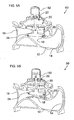
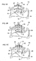
- the present invention relates to control valves for controlling flow of fluids and, in particular, it concerns a control valve in which a valve seat and a plurality of plug guides are integrated as parts of a guide-and-seat insert.
- valve seat In certain valves, access to the valve seat itself may be awkward. In such cases, attachment or replacement of the valve seat may be problematic.
- the collar is integrally formed with the plurality of plug guides.
- the tightening arrangement includes a plurality of bolts deployed within substantially radial threaded bores spaced around the collar.
- the plug includes a replaceable peripheral strip for contacting the plug guides.
- the plug includes a replaceable peripheral strip for contacting the plug guides, and wherein the replaceable peripheral strip is formed from a material having a lower wear-resistance than the second material.
- the plurality of plug guides are deployed such that, both under forward flow conditions from the inlet to the outlet and under reverse flow conditions from the outlet to the inlet, drag forces acting on the plug are opposed by three-point support of the plug wherein two of the three points are provided by two of the plug guides.
- a linear bearing deployed between the plug and the actuator such that, when the actuator moves towards the withdrawn position, the plug is free to move between an open position in which fluid flows from the inlet to the outlet and a closed position in which the plug closes against the closure surface of the valve seat so as to block the passage of fluid from the outlet to the inlet, thereby operating as a check valve.
- plug 24 is preferably provided with a replaceable peripheral strip 42 which serves as a bearing surface in sliding contact with plug guides 30.
- Peripheral strip 42 is preferably formed from a material having a lower wear-resistance than that of guide-and-seat insert 26, thereby localizing frictional wear in a simple-to-replace and low-cost component.
- Plug 24 also preferably features an elastomeric seal 44 deployed in facing relation to the sealing surface of valve seat 28 to seal against the valve seat.
- support point or "contact point” as used herein in relation to the support of plug 24 relate to localized physical contact regions, independent of the exact size and shape of the region where contact occurs.
- the support points between plug 24 and plug guides 30 are theoretically rectangles of overlap between the inward-facing surfaces of plug guides 30 and peripheral strip 42. In practice, as with any real mechanical system, forces are typically concentrated on a much smaller area.
Landscapes
- Engineering & Computer Science (AREA)
- General Engineering & Computer Science (AREA)
- Mechanical Engineering (AREA)
- Lift Valve (AREA)
- Fluid-Driven Valves (AREA)
Claims (14)
- Vanne de commande (10, 60, 70) servant à réguler la circulation de fluides comprenant :(a) un corps (12) pourvu d'une entrée (14), d'une sortie (16) et d'un passage parcouru par le fluide de ladite entrée à ladite sortie, ledit passage traversant une ouverture (18) ;(b) un actionneur (20) situé dans une chambre de commande (22) reliée audit corps (12) et configuré de manière à se déplacer le long d'un axe selon une amplitude allant d'une position rétractée à une position sortie ;(c) une prise (24) associée audit actionneur (20), de telle sorte que le mouvement dudit actionneur de ladite position rétractée vers la position sortie déplace ladite prise (24) vers ladite ouverture (18) ; et(d) un insert de guide et de siège (26) comprenant :de telle sorte que, lorsque ladite prise (24) est déplacée par ledit actionneur (20), ladite prise coulisse en prise avec au moins deux desdits guides de prise (30), et de telle sorte que, lorsque ledit actionneur se déplace jusqu'à ladite position sortie, ladite prise se ferme contre ladite surface de fermeture dudit siège de vanne, afin de bloquer le passage du fluide de ladite entrée à ladite sortie ;(i) un siège de vanne (28) configuré de manière à sceller ladite ouverture (18) et à former une surface de fermeture contre laquelle ladite prise (24) se ferme ;(ii) une pluralité de guides de prise (30) formés d'un seul tenant avec ledit siège de vanne (28) et s'étendant dudit siège de vanne vers ladite chambre de commande (22) ; et(iii) un collier (32) fixé à ou formé d'un seul tenant avec ladite pluralité de guides de prise (30) et configuré de manière à être serré contre une surface interne de ladite vanne de commande (10, 60, 70), afin de serrer ledit siège de vanne contre ladite ouverture ;
caractérisée en ce que ledit corps (12) et ladite chambre de commande (22) se rejoignent au niveau d'une partie col possédant une rainure périphérique (34), et en ce que ledit collier (32) est pourvu d'un élément de blocage périphérique (36) entourant une majeure partie dudit collier et d'un dispositif de serrage, ledit dispositif de serrage étant configuré de manière à déplacer ledit élément de blocage périphérique (36) à l'extérieur dans ladite rainure (34), afin de serrer ledit collier (32) contre ladite surface interne de ladite partie col. - Vanne de commande (10, 60, 70) selon la revendication 1, dans laquelle ledit collier (32) est formé d'un seul tenant avec ladite pluralité de guides de prise (30).
- Vanne de commande (10, 60, 70) selon les revendications 1 ou 2, dans laquelle ledit dispositif de serrage possède une pluralité de boulons (38) disposés dans des orifices filetés sensiblement radiaux répartis autour dudit collier (32).
- Vanne de commande (10, 60, 70) selon l'une quelconque des revendications précédentes, dans laquelle ladite rainure périphérique (34) possède une surface de serrage inclinée (40) disposée de telle manière que le déplacement vers l'extérieur dudit élément de blocage (36) contre ladite surface de serrage inclinée (40) déplace ledit insert de guide et de siège (26) vers ladite ouverture (18), afin de serrer ledit siège (28) contre ladite ouverture (18).
- Vanne de commande (10, 60, 70) selon l'une des revendications précédentes, dans laquelle ladite prise possède une bande périphérique remplaçable (42) destinée à venir en contact avec lesdits guides de prise (30).
- Vanne de commande (10, 60, 70) selon l'une quelconque des revendications 1 à 4, dans laquelle ledit corps (12) est formé à partir d'un premier matériau, et dans laquelle ledit insert de guide et de siège (26) est formé à partir d'un second matériau présentant une résistance à l'usure supérieure à celle dudit premier matériau.
- Vanne de commande (10, 60, 70) selon la revendication 6, dans laquelle ladite prise (24) possède une bande périphérique remplaçable (42) destinée à venir en contact avec lesdits guides de prise (30), et dans laquelle ladite bande périphérique remplaçable (42) est formée à partir d'un matériau présentant une résistance à l'usure inférieure à celle dudit second matériau.
- Vanne de commande (10, 60, 70) selon l'une quelconque des revendications précédentes, dans laquelle ladite prise (24) possède un axe central parallèle à un sens de déplacement dudit actionneur (20), et dans laquelle une direction depuis un centre de ladite ouverture (18) vers un centre de ladite sortie (16) définit un vecteur de flux principal (48), l'ensemble de ladite pluralité de guides de prise (30) étant espacés angulairement dudit vecteur de flux principal d'au moins 20 degrés.
- Vanne de commande (10, 60, 70) selon la revendication 8, dans laquelle deux de ladite pluralité de guides de prise (30) sont placés de manière symétrique selon un espacement angulaire donné de chaque côté dudit vecteur de flux principal (48).
- Vanne de commande (10, 60, 70) selon la revendication 9, dans laquelle ledit espacement angulaire donné est compris entre environ 40 et environ 50 degrés.
- Vanne de commande (10, 60, 70) selon l'une quelconque des revendications précédentes, dans laquelle ladite pluralité de guides de prise (30) sont disposés de telle sorte que, dans des conditions de circulation directe de ladite entrée à ladite sortie et dans des conditions de circulation inversée de ladite sortie à ladite entrée, le support à trois points de ladite prise, où deux des trois points sont fournis par deux desdits guides de prise (30), fasse obstacle aux forces de traînée agissant sur ladite prise.
- Vanne de commande (10) selon l'une quelconque des revendications précédentes, dans laquelle ledit actionneur possède une membrane souple (50) disposée de manière à subdiviser un volume interne de ladite chambre de commande (22).
- Vanne de commande (60) selon l'une quelconque des revendications 1 à 11, comprenant en outre un actionneur supplémentaire (62) situé à l'extérieur de ladite chambre de commande et relié mécaniquement à ladite prise.
- Vanne de commande (70) selon l'une quelconque des revendications 1 à 11, comprenant en outre un roulement linéaire (72) disposé entre ladite prise et ledit actionneur de telle sorte que, lorsque ledit actionneur se déplace vers une position rétractée, ladite prise soit libre de se déplacer entre une position d'ouverture où le fluide s'écoule de ladite entrée à ladite sortie et une position de fermeture où ladite prise se ferme contre ladite surface de fermeture dudit siège de vanne, de manière à bloquer le passage du fluide de ladite sortie vers ladite entrée, agissant ainsi comme un clapet de anti-retour.
Applications Claiming Priority (2)
| Application Number | Priority Date | Filing Date | Title |
|---|---|---|---|
| US11/390,243 US7458393B2 (en) | 2006-03-28 | 2006-03-28 | Control valve with integrated insert providing valve seat and plug guides |
| PCT/IL2007/000340 WO2007110859A2 (fr) | 2006-03-28 | 2007-03-15 | Vanne de commande avec insert intégré constituant un siège de vanne et des guides de prise |
Publications (3)
| Publication Number | Publication Date |
|---|---|
| EP1999400A2 EP1999400A2 (fr) | 2008-12-10 |
| EP1999400A4 EP1999400A4 (fr) | 2012-10-31 |
| EP1999400B1 true EP1999400B1 (fr) | 2016-01-13 |
Family
ID=38541527
Family Applications (1)
| Application Number | Title | Priority Date | Filing Date |
|---|---|---|---|
| EP07713360.1A Active EP1999400B1 (fr) | 2006-03-28 | 2007-03-15 | Vanne de commande avec insert integre fournissant un siege de vanne et des guides de prise |
Country Status (10)
| Country | Link |
|---|---|
| US (2) | US7458393B2 (fr) |
| EP (1) | EP1999400B1 (fr) |
| CN (1) | CN101501378B (fr) |
| AU (1) | AU2007230652B2 (fr) |
| BR (1) | BRPI0707231B1 (fr) |
| ES (1) | ES2567600T3 (fr) |
| MX (1) | MX2008008586A (fr) |
| RU (1) | RU2403479C2 (fr) |
| WO (1) | WO2007110859A2 (fr) |
| ZA (1) | ZA200805259B (fr) |
Families Citing this family (10)
| Publication number | Priority date | Publication date | Assignee | Title |
|---|---|---|---|---|
| US20120241033A1 (en) * | 2011-03-21 | 2012-09-27 | Jason David Clifford | Bonnet apparatus for use with fluid regulators |
| CN102221104A (zh) * | 2011-06-03 | 2011-10-19 | 山西建工申华暖通设备有限公司 | 平面密封的自力式流量控制阀 |
| US8740177B2 (en) | 2011-07-05 | 2014-06-03 | Rain Bird Corporation | Eccentric diaphragm valve |
| US9109717B2 (en) * | 2011-07-08 | 2015-08-18 | Fmc Technologies, Inc. | Electronically controlled pressure relief valve |
| US9915373B2 (en) * | 2011-07-08 | 2018-03-13 | Fmc Technologies, Inc. | Electronically controlled pressure relief valve |
| US20140042348A1 (en) * | 2012-08-08 | 2014-02-13 | T-3 Property Holdings, Inc. | Choke valve with short bonnet |
| JP7012100B2 (ja) * | 2017-05-26 | 2022-01-27 | ゲーエーアー トゥーヘンハーゲン ゲーエムベーハー | ダイアフラムシール付きダブルシートバルブおよび駆動装置 |
| CN111226067B (zh) * | 2018-09-27 | 2022-11-01 | Mt.H控制阀株式会社 | 控制阀装置 |
| FR3097608B1 (fr) * | 2019-06-24 | 2021-09-17 | Electricite De France | Robinet à soupape |
| CN117869602B (zh) * | 2024-03-11 | 2024-05-03 | 四川中油乐仪能源装备制造股份有限公司 | 节流截止放空阀 |
Family Cites Families (23)
| Publication number | Priority date | Publication date | Assignee | Title |
|---|---|---|---|---|
| US1807446A (en) * | 1927-04-19 | 1931-05-26 | Westinghouse Electric & Mfg Co | Valve |
| US1813222A (en) * | 1928-10-17 | 1931-07-07 | Bailey Meter Co | Balanced valve |
| US3157200A (en) * | 1961-12-26 | 1964-11-17 | Honeywell Inc | Reciprocating control valve |
| US3631891A (en) * | 1970-02-26 | 1972-01-04 | Grove Valve & Regulator Co | Silent valve |
| US3648718A (en) * | 1970-06-01 | 1972-03-14 | Foxboro Co | Valve structure |
| US3767159A (en) | 1972-08-03 | 1973-10-23 | Calgon Corp | Support seat for valves |
| US3971411A (en) * | 1974-03-07 | 1976-07-27 | Masoneilan International, Inc. | Variable resistance type throttling trim |
| US3990475A (en) * | 1975-01-08 | 1976-11-09 | Honeywell Inc. | Low noise valve trim |
| US4149563A (en) * | 1977-02-16 | 1979-04-17 | Copes-Vulcan, Inc. | Anti-cavitation valve |
| US4356996A (en) * | 1980-09-29 | 1982-11-02 | Quality Valve And Machine Works, Inc. | High pressure globe and check valve |
| CH654636A5 (de) * | 1982-03-02 | 1986-02-28 | Sulzer Ag | Verteilventil. |
| US4573489A (en) * | 1984-03-06 | 1986-03-04 | Murphy Management, Inc. | Dump valve |
| US4669702A (en) * | 1984-04-11 | 1987-06-02 | White Consolidated Industries, Inc. | Erosion resistant soft seated valve trim |
| US5082239A (en) * | 1988-06-20 | 1992-01-21 | Laminar Fluid Controls, Inc. | Radial flow valve assembly |
| US4834133A (en) * | 1988-09-28 | 1989-05-30 | Westinghouse Electric Corp. | Control valve |
| SE502342C2 (sv) * | 1991-04-24 | 1995-10-09 | Asea Atom Ab | Anordning för reparation eller ombyggnad av ventil |
| US5706856A (en) * | 1995-04-17 | 1998-01-13 | Lancaster; Robert D. | Valve apparatus |
| IL125196A (en) * | 1998-07-02 | 2001-06-14 | Rafael Magofim 1975 Ltd | Hydraulic diaphragm-actuated valve |
| US6886598B2 (en) * | 2001-01-08 | 2005-05-03 | Wood Group Pressure Control Limited | Choke restrictor devices and methods |
| US6382253B1 (en) * | 2001-02-13 | 2002-05-07 | Fisher Controls International, Inc. | Fluid pressure reduction device with integral guides |
| US6536472B2 (en) * | 2001-05-07 | 2003-03-25 | Fisher Controls International, Inc. | High performance fluid control valve |
| US6807985B2 (en) * | 2002-06-05 | 2004-10-26 | Dresser, Inc. | High rangeability control valve |
| US6997211B2 (en) * | 2003-07-03 | 2006-02-14 | Fisher Controls International Llc. | Multiple material valve plug for high temperature operation |
-
2006
- 2006-03-28 US US11/390,243 patent/US7458393B2/en not_active Expired - Lifetime
-
2007
- 2007-03-15 RU RU2008138370A patent/RU2403479C2/ru active
- 2007-03-15 BR BRPI0707231-7A patent/BRPI0707231B1/pt active IP Right Grant
- 2007-03-15 MX MX2008008586A patent/MX2008008586A/es active IP Right Grant
- 2007-03-15 CN CN2007800058829A patent/CN101501378B/zh active Active
- 2007-03-15 EP EP07713360.1A patent/EP1999400B1/fr active Active
- 2007-03-15 ES ES07713360.1T patent/ES2567600T3/es active Active
- 2007-03-15 WO PCT/IL2007/000340 patent/WO2007110859A2/fr not_active Ceased
- 2007-03-15 AU AU2007230652A patent/AU2007230652B2/en active Active
-
2008
- 2008-01-01 ZA ZA200805259A patent/ZA200805259B/xx unknown
- 2008-08-31 US US12/202,279 patent/US20080314463A1/en not_active Abandoned
Also Published As
| Publication number | Publication date |
|---|---|
| AU2007230652B2 (en) | 2012-04-12 |
| ZA200805259B (en) | 2009-07-29 |
| US20080314463A1 (en) | 2008-12-25 |
| EP1999400A2 (fr) | 2008-12-10 |
| BRPI0707231B1 (pt) | 2020-03-17 |
| CN101501378A (zh) | 2009-08-05 |
| RU2008138370A (ru) | 2010-05-10 |
| EP1999400A4 (fr) | 2012-10-31 |
| RU2403479C2 (ru) | 2010-11-10 |
| BRPI0707231A2 (pt) | 2011-04-26 |
| AU2007230652A1 (en) | 2007-10-04 |
| WO2007110859A3 (fr) | 2009-04-09 |
| MX2008008586A (es) | 2009-05-28 |
| ES2567600T3 (es) | 2016-04-25 |
| CN101501378B (zh) | 2011-06-08 |
| WO2007110859A2 (fr) | 2007-10-04 |
| US7458393B2 (en) | 2008-12-02 |
| US20070227600A1 (en) | 2007-10-04 |
Similar Documents
| Publication | Publication Date | Title |
|---|---|---|
| AU2007230652B2 (en) | Control valve with integrated insert providing valve seat and plug guides | |
| US9476186B2 (en) | Main valve with internal rigid structure | |
| US10260649B2 (en) | Fluidic device | |
| US20140124059A1 (en) | Valve assembly | |
| US20170108141A1 (en) | Rotary valve | |
| US20090121173A1 (en) | Valve assembly having a reinforced valve seat | |
| KR101096525B1 (ko) | 저온 및 고온에서 실링성능이 유지되는 버터플라이 밸브 | |
| CN107061777B (zh) | 调节-或闭锁装置 | |
| KR20140002317A (ko) | 볼밸브 | |
| CA2512994C (fr) | Soupape de commande guidee par une tige et sans douille | |
| US20190107212A1 (en) | Pinch valve | |
| US10145478B2 (en) | Top entry soft seats floating ball valve | |
| US10612676B2 (en) | Check valve having reverse-direction fluid supply function | |
| US20100301249A1 (en) | Butterfly valve plate sealing assembly | |
| CN100485191C (zh) | 具有改善的压力形成动力性的活塞泵 | |
| US20090120511A1 (en) | Standpipe direct float valve | |
| IL192405A (en) | Control valve with integral bushing with valve resident rails valve and blockage | |
| US10267424B2 (en) | Butterfly valve seat with seat cover | |
| US20130092856A1 (en) | Fluid control valve, in particular a seat valve | |
| US20060022159A1 (en) | Valve, actuator and control system therefor | |
| EP4196706B1 (fr) | Bague fendue montée sur un élastomère | |
| EP3458753B1 (fr) | Mécanisme d'empêchement de chargement de colonne de soupape à tiroir autonome | |
| US20250207672A1 (en) | Valve Assembly for Cooling Fluid | |
| CN208431422U (zh) | 一种三通换向阀 | |
| HU190830B (en) | Hydraulic control device |
Legal Events
| Date | Code | Title | Description |
|---|---|---|---|
| PUAI | Public reference made under article 153(3) epc to a published international application that has entered the european phase |
Free format text: ORIGINAL CODE: 0009012 |
|
| AK | Designated contracting states |
Kind code of ref document: A2 Designated state(s): AT BE BG CH CY CZ DE DK EE ES FI FR GB GR HU IE IS IT LI LT LU LV MC MT NL PL PT RO SE SI SK TR |
|
| AX | Request for extension of the european patent |
Extension state: AL BA HR MK RS |
|
| R17D | Deferred search report published (corrected) |
Effective date: 20090409 |
|
| RIC1 | Information provided on ipc code assigned before grant |
Ipc: F16K 1/44 20060101AFI20090416BHEP |
|
| 17P | Request for examination filed |
Effective date: 20090819 |
|
| RBV | Designated contracting states (corrected) |
Designated state(s): AT BE BG CH CY CZ DE DK EE ES FI FR GB GR HU IE IS IT LI LT LU LV MC MT NL PL PT RO SE SI SK TR |
|
| DAX | Request for extension of the european patent (deleted) | ||
| A4 | Supplementary search report drawn up and despatched |
Effective date: 20120928 |
|
| RIC1 | Information provided on ipc code assigned before grant |
Ipc: F16K 1/36 20060101AFI20120924BHEP Ipc: F16K 41/12 20060101ALI20120924BHEP Ipc: F16K 47/00 20060101ALI20120924BHEP |
|
| REG | Reference to a national code |
Ref country code: DE Ref legal event code: R079 Ref document number: 602007044553 Country of ref document: DE Free format text: PREVIOUS MAIN CLASS: F16K0011040000 Ipc: F16K0001360000 |
|
| GRAP | Despatch of communication of intention to grant a patent |
Free format text: ORIGINAL CODE: EPIDOSNIGR1 |
|
| RIC1 | Information provided on ipc code assigned before grant |
Ipc: F16K 41/12 20060101ALI20150617BHEP Ipc: F16K 1/36 20060101AFI20150617BHEP Ipc: F16K 47/00 20060101ALI20150617BHEP |
|
| INTG | Intention to grant announced |
Effective date: 20150716 |
|
| GRAS | Grant fee paid |
Free format text: ORIGINAL CODE: EPIDOSNIGR3 |
|
| GRAA | (expected) grant |
Free format text: ORIGINAL CODE: 0009210 |
|
| AK | Designated contracting states |
Kind code of ref document: B1 Designated state(s): AT BE BG CH CY CZ DE DK EE ES FI FR GB GR HU IE IS IT LI LT LU LV MC MT NL PL PT RO SE SI SK TR |
|
| REG | Reference to a national code |
Ref country code: GB Ref legal event code: FG4D |
|
| REG | Reference to a national code |
Ref country code: CH Ref legal event code: EP |
|
| REG | Reference to a national code |
Ref country code: IE Ref legal event code: FG4D |
|
| REG | Reference to a national code |
Ref country code: AT Ref legal event code: REF Ref document number: 770753 Country of ref document: AT Kind code of ref document: T Effective date: 20160215 |
|
| REG | Reference to a national code |
Ref country code: DE Ref legal event code: R096 Ref document number: 602007044553 Country of ref document: DE |
|
| REG | Reference to a national code |
Ref country code: FR Ref legal event code: PLFP Year of fee payment: 10 |
|
| REG | Reference to a national code |
Ref country code: ES Ref legal event code: FG2A Ref document number: 2567600 Country of ref document: ES Kind code of ref document: T3 Effective date: 20160425 |
|
| REG | Reference to a national code |
Ref country code: LT Ref legal event code: MG4D |
|
| REG | Reference to a national code |
Ref country code: NL Ref legal event code: MP Effective date: 20160113 |
|
| REG | Reference to a national code |
Ref country code: AT Ref legal event code: MK05 Ref document number: 770753 Country of ref document: AT Kind code of ref document: T Effective date: 20160113 |
|
| PG25 | Lapsed in a contracting state [announced via postgrant information from national office to epo] |
Ref country code: NL Free format text: LAPSE BECAUSE OF FAILURE TO SUBMIT A TRANSLATION OF THE DESCRIPTION OR TO PAY THE FEE WITHIN THE PRESCRIBED TIME-LIMIT Effective date: 20160113 |
|
| PG25 | Lapsed in a contracting state [announced via postgrant information from national office to epo] |
Ref country code: FI Free format text: LAPSE BECAUSE OF FAILURE TO SUBMIT A TRANSLATION OF THE DESCRIPTION OR TO PAY THE FEE WITHIN THE PRESCRIBED TIME-LIMIT Effective date: 20160113 Ref country code: GR Free format text: LAPSE BECAUSE OF FAILURE TO SUBMIT A TRANSLATION OF THE DESCRIPTION OR TO PAY THE FEE WITHIN THE PRESCRIBED TIME-LIMIT Effective date: 20160414 Ref country code: IT Free format text: LAPSE BECAUSE OF FAILURE TO SUBMIT A TRANSLATION OF THE DESCRIPTION OR TO PAY THE FEE WITHIN THE PRESCRIBED TIME-LIMIT Effective date: 20160113 |
|
| PG25 | Lapsed in a contracting state [announced via postgrant information from national office to epo] |
Ref country code: LV Free format text: LAPSE BECAUSE OF FAILURE TO SUBMIT A TRANSLATION OF THE DESCRIPTION OR TO PAY THE FEE WITHIN THE PRESCRIBED TIME-LIMIT Effective date: 20160113 Ref country code: PT Free format text: LAPSE BECAUSE OF FAILURE TO SUBMIT A TRANSLATION OF THE DESCRIPTION OR TO PAY THE FEE WITHIN THE PRESCRIBED TIME-LIMIT Effective date: 20160513 Ref country code: PL Free format text: LAPSE BECAUSE OF FAILURE TO SUBMIT A TRANSLATION OF THE DESCRIPTION OR TO PAY THE FEE WITHIN THE PRESCRIBED TIME-LIMIT Effective date: 20160113 Ref country code: IS Free format text: LAPSE BECAUSE OF FAILURE TO SUBMIT A TRANSLATION OF THE DESCRIPTION OR TO PAY THE FEE WITHIN THE PRESCRIBED TIME-LIMIT Effective date: 20160513 Ref country code: LT Free format text: LAPSE BECAUSE OF FAILURE TO SUBMIT A TRANSLATION OF THE DESCRIPTION OR TO PAY THE FEE WITHIN THE PRESCRIBED TIME-LIMIT Effective date: 20160113 Ref country code: BE Free format text: LAPSE BECAUSE OF NON-PAYMENT OF DUE FEES Effective date: 20160331 Ref country code: SE Free format text: LAPSE BECAUSE OF FAILURE TO SUBMIT A TRANSLATION OF THE DESCRIPTION OR TO PAY THE FEE WITHIN THE PRESCRIBED TIME-LIMIT Effective date: 20160113 Ref country code: AT Free format text: LAPSE BECAUSE OF FAILURE TO SUBMIT A TRANSLATION OF THE DESCRIPTION OR TO PAY THE FEE WITHIN THE PRESCRIBED TIME-LIMIT Effective date: 20160113 |
|
| REG | Reference to a national code |
Ref country code: DE Ref legal event code: R097 Ref document number: 602007044553 Country of ref document: DE |
|
| PG25 | Lapsed in a contracting state [announced via postgrant information from national office to epo] |
Ref country code: MC Free format text: LAPSE BECAUSE OF FAILURE TO SUBMIT A TRANSLATION OF THE DESCRIPTION OR TO PAY THE FEE WITHIN THE PRESCRIBED TIME-LIMIT Effective date: 20160113 Ref country code: EE Free format text: LAPSE BECAUSE OF FAILURE TO SUBMIT A TRANSLATION OF THE DESCRIPTION OR TO PAY THE FEE WITHIN THE PRESCRIBED TIME-LIMIT Effective date: 20160113 Ref country code: LU Free format text: LAPSE BECAUSE OF FAILURE TO SUBMIT A TRANSLATION OF THE DESCRIPTION OR TO PAY THE FEE WITHIN THE PRESCRIBED TIME-LIMIT Effective date: 20160315 Ref country code: DK Free format text: LAPSE BECAUSE OF FAILURE TO SUBMIT A TRANSLATION OF THE DESCRIPTION OR TO PAY THE FEE WITHIN THE PRESCRIBED TIME-LIMIT Effective date: 20160113 |
|
| REG | Reference to a national code |
Ref country code: CH Ref legal event code: PL |
|
| PLBE | No opposition filed within time limit |
Free format text: ORIGINAL CODE: 0009261 |
|
| STAA | Information on the status of an ep patent application or granted ep patent |
Free format text: STATUS: NO OPPOSITION FILED WITHIN TIME LIMIT |
|
| PG25 | Lapsed in a contracting state [announced via postgrant information from national office to epo] |
Ref country code: SK Free format text: LAPSE BECAUSE OF FAILURE TO SUBMIT A TRANSLATION OF THE DESCRIPTION OR TO PAY THE FEE WITHIN THE PRESCRIBED TIME-LIMIT Effective date: 20160113 Ref country code: CZ Free format text: LAPSE BECAUSE OF FAILURE TO SUBMIT A TRANSLATION OF THE DESCRIPTION OR TO PAY THE FEE WITHIN THE PRESCRIBED TIME-LIMIT Effective date: 20160113 Ref country code: RO Free format text: LAPSE BECAUSE OF FAILURE TO SUBMIT A TRANSLATION OF THE DESCRIPTION OR TO PAY THE FEE WITHIN THE PRESCRIBED TIME-LIMIT Effective date: 20160113 |
|
| 26N | No opposition filed |
Effective date: 20161014 |
|
| REG | Reference to a national code |
Ref country code: IE Ref legal event code: MM4A |
|
| PG25 | Lapsed in a contracting state [announced via postgrant information from national office to epo] |
Ref country code: BE Free format text: LAPSE BECAUSE OF FAILURE TO SUBMIT A TRANSLATION OF THE DESCRIPTION OR TO PAY THE FEE WITHIN THE PRESCRIBED TIME-LIMIT Effective date: 20160113 |
|
| PG25 | Lapsed in a contracting state [announced via postgrant information from national office to epo] |
Ref country code: IE Free format text: LAPSE BECAUSE OF NON-PAYMENT OF DUE FEES Effective date: 20160315 Ref country code: LI Free format text: LAPSE BECAUSE OF NON-PAYMENT OF DUE FEES Effective date: 20160331 Ref country code: CH Free format text: LAPSE BECAUSE OF NON-PAYMENT OF DUE FEES Effective date: 20160331 |
|
| PG25 | Lapsed in a contracting state [announced via postgrant information from national office to epo] |
Ref country code: BG Free format text: LAPSE BECAUSE OF FAILURE TO SUBMIT A TRANSLATION OF THE DESCRIPTION OR TO PAY THE FEE WITHIN THE PRESCRIBED TIME-LIMIT Effective date: 20160413 Ref country code: SI Free format text: LAPSE BECAUSE OF FAILURE TO SUBMIT A TRANSLATION OF THE DESCRIPTION OR TO PAY THE FEE WITHIN THE PRESCRIBED TIME-LIMIT Effective date: 20160113 |
|
| REG | Reference to a national code |
Ref country code: FR Ref legal event code: PLFP Year of fee payment: 11 |
|
| PG25 | Lapsed in a contracting state [announced via postgrant information from national office to epo] |
Ref country code: MT Free format text: LAPSE BECAUSE OF FAILURE TO SUBMIT A TRANSLATION OF THE DESCRIPTION OR TO PAY THE FEE WITHIN THE PRESCRIBED TIME-LIMIT Effective date: 20160113 |
|
| REG | Reference to a national code |
Ref country code: FR Ref legal event code: PLFP Year of fee payment: 12 |
|
| PG25 | Lapsed in a contracting state [announced via postgrant information from national office to epo] |
Ref country code: HU Free format text: LAPSE BECAUSE OF FAILURE TO SUBMIT A TRANSLATION OF THE DESCRIPTION OR TO PAY THE FEE WITHIN THE PRESCRIBED TIME-LIMIT; INVALID AB INITIO Effective date: 20070315 Ref country code: CY Free format text: LAPSE BECAUSE OF FAILURE TO SUBMIT A TRANSLATION OF THE DESCRIPTION OR TO PAY THE FEE WITHIN THE PRESCRIBED TIME-LIMIT Effective date: 20160113 |
|
| PG25 | Lapsed in a contracting state [announced via postgrant information from national office to epo] |
Ref country code: MT Free format text: LAPSE BECAUSE OF FAILURE TO SUBMIT A TRANSLATION OF THE DESCRIPTION OR TO PAY THE FEE WITHIN THE PRESCRIBED TIME-LIMIT Effective date: 20160331 |
|
| PGFP | Annual fee paid to national office [announced via postgrant information from national office to epo] |
Ref country code: ES Payment date: 20250404 Year of fee payment: 19 |
|
| PGFP | Annual fee paid to national office [announced via postgrant information from national office to epo] |
Ref country code: GB Payment date: 20260317 Year of fee payment: 20 |
|
| PGFP | Annual fee paid to national office [announced via postgrant information from national office to epo] |
Ref country code: DE Payment date: 20260318 Year of fee payment: 20 |
|
| PGFP | Annual fee paid to national office [announced via postgrant information from national office to epo] |
Ref country code: FR Payment date: 20260317 Year of fee payment: 20 |
|
| PGFP | Annual fee paid to national office [announced via postgrant information from national office to epo] |
Ref country code: TR Payment date: 20260305 Year of fee payment: 20 |