EP1999413B1 - Parabolsolarrinnensysteme mit dreh-nachführungsmittel - Google Patents
Parabolsolarrinnensysteme mit dreh-nachführungsmittel Download PDFInfo
- Publication number
- EP1999413B1 EP1999413B1 EP06727758A EP06727758A EP1999413B1 EP 1999413 B1 EP1999413 B1 EP 1999413B1 EP 06727758 A EP06727758 A EP 06727758A EP 06727758 A EP06727758 A EP 06727758A EP 1999413 B1 EP1999413 B1 EP 1999413B1
- Authority
- EP
- European Patent Office
- Prior art keywords
- reflectors
- solar trough
- parabolic
- field system
- thermal receiver
- Prior art date
- Legal status (The legal status is an assumption and is not a legal conclusion. Google has not performed a legal analysis and makes no representation as to the accuracy of the status listed.)
- Expired - Lifetime
Links
Images



Classifications
-
- F—MECHANICAL ENGINEERING; LIGHTING; HEATING; WEAPONS; BLASTING
- F24—HEATING; RANGES; VENTILATING
- F24S—SOLAR HEAT COLLECTORS; SOLAR HEAT SYSTEMS
- F24S30/00—Arrangements for moving or orienting solar heat collector modules
- F24S30/40—Arrangements for moving or orienting solar heat collector modules for rotary movement
- F24S30/42—Arrangements for moving or orienting solar heat collector modules for rotary movement with only one rotation axis
- F24S30/425—Horizontal axis
-
- F—MECHANICAL ENGINEERING; LIGHTING; HEATING; WEAPONS; BLASTING
- F24—HEATING; RANGES; VENTILATING
- F24S—SOLAR HEAT COLLECTORS; SOLAR HEAT SYSTEMS
- F24S20/00—Solar heat collectors specially adapted for particular uses or environments
- F24S20/20—Solar heat collectors for receiving concentrated solar energy, e.g. receivers for solar power plants
-
- F—MECHANICAL ENGINEERING; LIGHTING; HEATING; WEAPONS; BLASTING
- F24—HEATING; RANGES; VENTILATING
- F24S—SOLAR HEAT COLLECTORS; SOLAR HEAT SYSTEMS
- F24S23/00—Arrangements for concentrating solar-rays for solar heat collectors
- F24S23/70—Arrangements for concentrating solar-rays for solar heat collectors with reflectors
- F24S23/74—Arrangements for concentrating solar-rays for solar heat collectors with reflectors with trough-shaped or cylindro-parabolic reflective surfaces
-
- F—MECHANICAL ENGINEERING; LIGHTING; HEATING; WEAPONS; BLASTING
- F24—HEATING; RANGES; VENTILATING
- F24S—SOLAR HEAT COLLECTORS; SOLAR HEAT SYSTEMS
- F24S23/00—Arrangements for concentrating solar-rays for solar heat collectors
- F24S23/70—Arrangements for concentrating solar-rays for solar heat collectors with reflectors
- F24S23/79—Arrangements for concentrating solar-rays for solar heat collectors with reflectors with spaced and opposed interacting reflective surfaces
-
- Y—GENERAL TAGGING OF NEW TECHNOLOGICAL DEVELOPMENTS; GENERAL TAGGING OF CROSS-SECTIONAL TECHNOLOGIES SPANNING OVER SEVERAL SECTIONS OF THE IPC; TECHNICAL SUBJECTS COVERED BY FORMER USPC CROSS-REFERENCE ART COLLECTIONS [XRACs] AND DIGESTS
- Y02—TECHNOLOGIES OR APPLICATIONS FOR MITIGATION OR ADAPTATION AGAINST CLIMATE CHANGE
- Y02E—REDUCTION OF GREENHOUSE GAS [GHG] EMISSIONS, RELATED TO ENERGY GENERATION, TRANSMISSION OR DISTRIBUTION
- Y02E10/00—Energy generation through renewable energy sources
- Y02E10/40—Solar thermal energy, e.g. solar towers
-
- Y—GENERAL TAGGING OF NEW TECHNOLOGICAL DEVELOPMENTS; GENERAL TAGGING OF CROSS-SECTIONAL TECHNOLOGIES SPANNING OVER SEVERAL SECTIONS OF THE IPC; TECHNICAL SUBJECTS COVERED BY FORMER USPC CROSS-REFERENCE ART COLLECTIONS [XRACs] AND DIGESTS
- Y02—TECHNOLOGIES OR APPLICATIONS FOR MITIGATION OR ADAPTATION AGAINST CLIMATE CHANGE
- Y02E—REDUCTION OF GREENHOUSE GAS [GHG] EMISSIONS, RELATED TO ENERGY GENERATION, TRANSMISSION OR DISTRIBUTION
- Y02E10/00—Energy generation through renewable energy sources
- Y02E10/40—Solar thermal energy, e.g. solar towers
- Y02E10/47—Mountings or tracking
Definitions
- This invention relates to the developments on parabolic trough-shaped collectors which concentrate the sunlight on a focus and convert it into another energy forms such as heat and electricity.
- trough collectors solar trough field system
- These systems comprise trough-shaped long parabolic reflectors, thermal receiver tubes which are placed on the focus of the reflectors where beams coming from the reflector are collected and in which a fluid exists, and a rotating mechanism which directs the reflectors to the location where the sun is.
- the beams coming to the reflectors which are directed towards the sun are reflected and collected on the thermal receiver tube which is located on the focus of the reflector.
- Thermal receiver tube is provided with two nested tubes where a vacuum setting is located in the space therebetween. A fluid, which provides the heat transfer, is passed through the inner tube.
- the outer tube is made of glass.
- this tube By concentrating the beams coming from the reflectors on the thermal receiver tube, this tube reaches very high temperatures; therefore, the fluid located in the inner tube can be heated. Heat energy can be converted into the electric energy, when desired, by means of this fluid which reaches high temperatures.
- thermal receiver tubes used in these systems are many meters long, said thermal receiver tubes follow the sun together with the reflectors, outer parts thereof are made of glass, such factors increase their possibility of breaking during operation.
- dynamic and static forces which are generated by the wind can cause both reflectors and tubes to break.
- a truss structure is formed to support the reflectors on their convex sides. However, this structure decreases only the rate of breaking and is not a complete solution for breaking.
- the vibrations generated as a result of the movement which is made by the system for directing towards the sun can also cause the glass tubes to break.
- the solar trough field systems which are built on California (USA) by LUZ can be given as an example for these systems.
- the parabolic reflectors which are many meters long and the thermal receiver tubes which are located on their focus are rotated together.
- the most fundamental problem of this system is that the thermal receiver tubes which are made of a fragile material are movable. As long as the thermal receiver tubes are movable, they are subjected to more torque load and the flexible hoses are used in the connections of the beginning and ending points of the parabolic reflectors with the fixed tubes.
- the thermal receiver tubes which are subjected to the torque loads have a higher possibility of breaking.
- the flexible hose connection is not a safe system since the temperature of the fluid which is transferred within the thermal receiver tube is 300-500°C.
- the truss structure, which supports the parabolic mirrors is also weak against the torque and the moment loads acting due to the drive unit of the system and the wind. Because of these loads, the parabolic reflectors are frequently broken, thus causing the operating costs to increase.
- trough-shaped parabolic reflectors reflect the sunlight to the receiver tube, thus allowing the fluid located in the tube to heat.
- the receiver tube is kept constant and located on the focus of the parabolic reflectors.
- Circular-shaped support parts are located on the both ends of the parabolic reflectors, and the center of said support parts are such that they coincide with the focus of the reflectors.
- Circular support parts are rotated around the center axes in order system to follow the sun, thus allowing the parabolic reflectors to rotate around the immovable receiver tube located on the focus thereof.
- the breaking problems arising from the deformation are reduced.
- a parabolic structured reflector is supported by a cylindrical profile passing underneath thereof and a circular structure located on the edges thereof.
- a thermal receiver tube placed so as to pass from the center of the semicircle which is located on edges thereof.
- the reflector is placed onto the support wheels which stand opposite to each other and rotated by means of the main motor. Standing wheels too close to each other and locating them on the lowest portion of the reflectors cause the reflectors to be more affected by the wind loads.
- all reflective panels are rotated by a single motor similar to US4559926 .
- a more sensitive sun follow-up is provided by lesser capacity motors running synchronously with each other instead of a single motor unit which has sufficient capacity to rotate all collectors, and also even if some of the motors fail there is no need to stop entire collector system.
- it is considered to use multi-piece parabolic reflectors instead of single-piece parabolic reflectors. Owing to multi-piece parabolic structure, even if some reflector parts are broken, the system can continue to run without suffering too much efficiency loss. Manufacturing cost of the single-piece parabolic reflectors in the systems of the prior art accounts for 20% of the entire system cost, which is an important part thereof.
- a parabolic reflectors system comprising flat surface multi-piece reflectors proposed with the invention reduces this cost significantly.
- an advantage obtained from keeping the thermal receiver tubes constant is the direct steam generation. Difficulties are encountered during the direct steam generation in the thermal receiver tubes with flexible hose connection or rotary joint connection which are used in the prior art, and the generated steam leaks out to external environment from said connection points.
- An aim of the invention is to provide solar collectors with parabolic reflector, which rotate around a fixed thermal receiver tube, to direct more sensitively towards the sun by using synchronously running motors with each other, and to have the motors run, even if some of them fail, without any need to stop entire collector system.
- Another aim of the invention is to use guy wires between the circle and its center in order to reduce the weight of the support circles used at certain intervals throughout the parabolic reflectors, and also to reduce the weight of the present circle more and use them at more frequent intervals, thus increasing the resistance against the wind loads.
- Yet another aim of the invention is to decrease the maintenance and replacement expenses which will arise in case of breaking the parabolic reflectors and to ensure the use of multi-piece parabolic mirrors instead of single-piece ones in order to prevent the system from suffering too much efficiency loss even if some reflector parts are broken.
- Another aim of the invention is to use heat fins in the thermal receiver tubes, thus providing an efficiency increase.
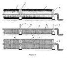
- FIG. 1 provides a side view of the inventive solar trough field system (A).
- a solar trough field system (A) comprises multiple parabolic reflectors (1), support circles (3) of which the center coincides with the focus of the parabolic reflector (1) and which are used in order to support the reflector (1); core mechanisms (2) which are located on the center of the circles (3); guy wires (4) which connect the circle (3) and the core mechanism (2) to each other; side support units (5, 5') which bear the support circles (3) from their outer surfaces; lightweight filling materials (6) which support the reflectors (1) from their lower parts; thermal receiver tubes (11) which pass through the center axis of the circles (3).
- the solar trough field system (A) is rotated around the center axis of the circles (3) and in this way; the parabolic reflectors (1) are also directed towards the sun by rotating in this rotation axis which is their focus.
- the parallel beams coming from the sun are concentrated in the focus of the reflectors (1), i.e. thermal receiver tubes (11).
- the protective lid (8) which is shown in fig. 2 , is used to protect the side support units (5, 5') and the wheels (7, 7') from the external effects.
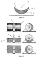
- Fig. 3 provides the front views of the solar trough field system (A) in a position where it is rotated to different directions. Since the solar trough field systems consist of the parabolic reflectors which are many meters long, they must be both robust against the wind loads and have a lesser energy consuming structure in order to work more efficiently. It is important them to be lightweight in order to spend lesser energy.
- the inventive solar trough field system (A) which is designed by starting from this point, has the support circles (3) between the subsequent parabolic reflectors (1) as shown in fig. 3 .
- Fig. 4 provides the view of the Z-Z section from fig.
- FIG. 3 wherein the lower lids (10) for supporting the reflectors (1) which are located in the lower parts of the parabolic reflectors (1), and the lightweight filling material (6) which fills the space between the lower lids and the reflectors (1) are shown.
- the lower lids are shown in the circular cross section as an example in fig. 3 and 4 .
- support profiles (9) are used for the connection of every support circle (3) to each other and to the integrated structure composed of the reflector (1), the lower lid (10) and the lightweight filling material (6).
- Fig. 5 provides the side and front views of a part of the solar trough field system during the operation.
- Fig. 6 provides the side and front detailed views of the core mechanism (2) of the solar trough field system (A).
- the core mechanism (2) comprises an inner circle (12) to which guy ropes are connected, a ball or cylindrical roller bearing (13) which is located in the center of the inner circle (12), a seat (14) into which the inner ring of the bearing (13) is placed and a thermal receiver tube (11) which passes through this seat.
- the thermal receiver tube (11) consists of two tubes which are nested, concentric with each other and have a vacuum compartment (16) therebetween.
- a fluid is passed through the inner tube, called as transfer tube (17), with high heat conductivity for the heat transfer.
- Outer glass tube (15) allows the beams coming from the parabolic reflectors to reach directly to the transfer tube (17).
- the thermal receiver tubes (11) are used in many meters long in the solar trough field systems. In order to decrease the possibility of breaking the glass tubes (15) which are located in these tubes (11), the thermal receiver tubes (11) are kept completely immovable in the inventive solar trough field system (A).
- the thermal receiver tube (11) concentrically with the housing (14) is placed into this housing (14) which is in an immovable position and the tube (11) is secured.
- the support circles (3) are connected to the inner circle (12) through guy wires (4) and can rotate around the fixed housing (14) through the bearing (13) in the center of the inner circle (12).
- Fig. 7 provides the side and perspective views of the parabolic reflectors (1) in the inventive solar trough field system (A).
- the improvement made on the parabolic reflectors (1) with the invention is that the reflectors (1) are produced as longitudinal multi-piece instead of single-piece. Thanks to this multi-piece structure, even if some reflector parts are broken, it is easy to change them. In addition, the breaking of single-piece reflectors due to the external effects can damage the substantial part of the reflectors. Owing to multi-piece structure, only the reflectors which remain under the effect are broken, and the possibility of damage to entire parabola decreases.
- the system can continue to run without suffering too much efficiency loss.
- the edge width of those which are close to the center of the parabola is narrow and the width of these reflector parts increases towards the sides of the parabola.
- the surfaces of the multi-piece parabolic reflectors which face towards the thermal receiver tubes can be produced in two different ways. The first alternative is to make these surfaces planar. The reflectors which are placed on the concave surfaces of this parabolic solar trough are placed on this trough such that they reflect the light coming onto their plane surfaces to the thermal receiver tube.
- the second alternative is that said surfaces of these multi-piece reflectors are each in the form of a parabolic cross section.
- said parabolic cross sectioned reflectors are positioned one after the other on the concave surface of a parabolic solar trough again, a multi-piece parabolic reflector system, where the focal point of each is the thermal receiver tube, is produced.
- Fig. 8 provides a side view of an exemplary hyperbolic collector. In this demonstration, it is shown that the beams which come to reflector as parallel and at certain angles concentrate on the bottom side of the hyperbola.
- An improvement made with the invention is the use of a hyperbolic collector around the thermal receiver tube.
- Fig. 9 provides a side view of a hyperbolic collector adapted to the thermal receiver tube. The use of a hyperbolic collector was considered in order to concentrate the beams coming angularly as well as the parallel beams coming from the parabolic reflectors in the thermal receiver tube.
- Fig. 9a shows a hyperbolic collector (18) placed around the thermal receiver tube (11 ").
- the bottom side of this hyperbolic collector (18) was produced as circular cross sectioned such that it somewhat surrounds the thermal receiver tube (11") and then hyperbolic form was given to its arms extending towards two sides. In this way, the beams coming parallel and angularly from the parabolic reflector reflect from the inner surface of the hyperbolic collector (18) and concentrate on the thermal receiver tube (11"), and the concentration of the light coming on the tube (11") is increased, thus ensuring the more efficient operation of the solar trough field system (A).
- the thermal receiver tube (11 ") which is used herein is made of a tube with high heat conductivity. Since there is a hyperbolic collector (18) around said thermal receiver tube (11"), there is no need to use a glass tube in its outer side.
- FIG. 9b An improvement made in order to allow the efficiency increase is also shown in fig. 9b .
- this tube (11') is made of glass and the heat fins (19) with high heat conductivity are used therein in order to heat the fluid passing through this tube (11') more quickly.
- Said heat fins (19) may be the fins which are in the form of a plate from the profile; however they may be used in the form of a bar as shown in fig. 10 as well. Plate-shaped fins provide manufacturing and mounting easiness compared to bar-shaped fins.
- Fig. 10 provides the side and perspective views of the heat fins (19) structure which is located inside the thermal receiver tube (11').
- the heat fins (19) are located longitudinally inside the glass tube (15a) and integrally with this tube (15a).
- thermal receiver tube (11") which is an exemplary embodiment of the invention, is somewhat surrounded by the hyperbolic collector (18), it is less affected by the external environment conditions. Therefore, since a second glass tube is not preferred in the thermal receiver tube (11"), there is no need to perform the operations such as combining the glass tubes which are many meters long, creating a vacuum space, providing tightness; and there arises an opportunity to save money on the issues such as material, workmanship, maintenance, repair owing to the absence of these glass tubes which are the most fragile components of the system even if they are in a fixed position.
- Fig. 11 a provides a schematic view of the light collection field in the solar troughs used in the prior art.
- Fig. 11b provides a schematic view of the light collection field in the inventive solar trough.
- the light collection field in the inventive solar trough can be enlarged approximately 1.5 times compared to the prior art.
- the light collection field in the inventive solar trough can be enlarged 2 times or more.
- the arms of the parabolic form should be made such that they extend towards the outside of the support circle.
- An example which demonstrates this embodiment is shown in fig. 12 .
- the temperature of the fluid which passes through the thermal receiver tubes can reach approximately 400°C in the prior art, the temperature of the fluid which passes through the thermal receiver tube can increase to 600°C, even 750°C by means of the elongated parabola arms in the inventive systems with increased light collection field.
Landscapes
- Engineering & Computer Science (AREA)
- Physics & Mathematics (AREA)
- Life Sciences & Earth Sciences (AREA)
- Sustainable Development (AREA)
- Sustainable Energy (AREA)
- Thermal Sciences (AREA)
- Chemical & Material Sciences (AREA)
- Combustion & Propulsion (AREA)
- Mechanical Engineering (AREA)
- General Engineering & Computer Science (AREA)
- Mounting And Adjusting Of Optical Elements (AREA)
- Optical Elements Other Than Lenses (AREA)
Claims (18)
- Solarrinnenfeldsystem (A), das dazu verwendet wird, Sonnenlicht auf einen Brennpunkt zu bündeln und es in andere Energieformen wie Wärme und Elektrizität umzuwandeln, umfassend mehrere Parabolreflektoren (1); Stützringe (3), deren Mittelpunkt mit dem Brennpunkt des Parabolreflektors (1) zusammenfällt, und die dazu verwendet werden, um den Reflektor (1) abzustützen und die zwischen den aufeinanderfolgenden Parabolreflektoren (1) angeordnet sind; Kernmechanismen (2), die am Mittelpunkt der Ringe (3) angeordnet sind; Verankerungsseile (4), welche den Ring (3) und den Kernmechanismus (2) miteinander verbinden; Seitenstützeinheiten (5, 5'), welche die Stützringe (3) von ihren Außenflächen her tragen; leichte Füllmaterialien (6), welche die Reflektoren (1) von ihren unteren Bereichen her abstützen; Wärmeaufnehmerrohre (11), die durch die Mittelachse der Ringe (3) verlaufen; und wobei das System um die Mittelachse der Ringe (3) gedreht wird und auf diese Weise auch die Parabolreflektoren (1) durch Drehung um diese Rotationsachse, die ihr Brennpunkt ist, zur Sonne hin ausgerichtet werden, sodass die parallel von der Sonne kommenden Strahlen auf die Wärmeaufnehmerrohre (11) gebündelt werden, die am Brennpunkt der Reflektoren (1) angeordnet sind, dadurch gekennzeichnet, dass, um sicherzustellen, dass sich die Ringe (3) um ihre Mittelpunkte drehen und dabei die Seitenstützeinheiten (5, 5') berühren und somit die als Einheit mit den Ringen (3) ausgebildeten Reflektoren (1) zur Sonne hin ausgerichtet werden, mehrere synchron miteinander laufende Motoren, Untersetzungseinheiten, welche die von diesem Motor übernommene Bewegung zum Drehmomentanstieg nutzen, und Bewegungsmechanismen verwendet werden, welche die Parabolreflektoren (1) mit diesen Untersetzungseinheiten drehen, und diese besagten Bewegungsmechanismen nahe den Stützringen (3) angeordnet sind.
- Solarrinnenfeldsystem (A) nach Anspruch 1, wobei es darüber hinaus frei drehbare Räder (7, 7') an den Seitenstützeinheiten (5, 5'), wo sie die Ringe (3) berühren, umfasst.
- Solarrinnenfeldsystem (A) nach Anspruch 1, wobei es sich bei den Gruppen der Räder (7, 7'), die an den Seitenstützeinheiten (5, 5'), wo sie die Ringe (3) berühren, angeordnet sind, um die Teile der Mechanismen handelt, welche die Ringe (3) bewegen.
- Solarrinnenfeldsystem (A) nach Anspruch 1, wobei eine Schutzabdeckung (8) darauf verwendet wird, um die Seitenstützeinheiten (5, 5') und die Räder (7, 7') vor Außeneinwirkungen zu schützen.
- Solarrinnenfeldsystem (A) nach Anspruch 1, wobei, um ihre Festigkeit gegen Windlasten zu erhöhen und einen weniger energieverbrauchenden Aufbau zu haben, die unteren Abdeckungen (10) zum Abstützen der Reflektoren (1), die in den unteren Bereichen der Parabolreflektoren (1) angeordnet sind, und das leichte Füllmaterial (6), das den Raum zwischen den unteren Abdeckungen und den Reflektoren (1) füllt, verwendet werden.
- Solarrinnenfeldsystem (A) nach Anspruch 5, wobei die unteren Abdeckungen (10) im Kreisquerschnitt sind.
- Solarrinnenfeldsystem (A) nach Anspruch 5, wobei Stützprofile (9) verwendet werden, um jeden Stützring (3) mit einem anderen Stützring und dem integrierten Aufbau zu verbinden, der aus dem Reflektor (1), der unteren Abdeckung (10) und dem leichten Hüllmaterial (6) besteht.
- Solarrinnenfeldsystem (A) nach Anspruch 1, wobei der Kernmechanismus (2) darüber hinaus einen Innenring (12), an den ein Ende der Verankerungsseile angeschlossen ist, während sein anderes Ende an die Stützringe (3) angeschlossen ist, ein Kugel- oder Zylinderrollenlager (13), das in der Mitte des Innenrings (12) angeordnet ist, ein Gehäuse (14), in das der Innenkranz des Lagers (13) eingesetzt ist, und ein Wärmeaufnehmerrohr (11) umfasst, das in einer feststehenden Position in diesem Gehäuse angeordnet ist.
- Solarrinnenfeldsystem (A) nach Anspruch 1, wobei die Parabolreflektoren (1) längsverlaufend mehrteilig und nicht einteilig verwendet werden, um zu verhindern, dass in dem Fall, dass sie aufgrund von Außeneinwirkungen zu Bruch gehen, alle von ihnen beschädigt werden, und um die zu Bruch gegangenen Reflektoren mühelos austauschen zu können.
- Solarrinnenfeldsystem (A) nach Anspruch 9, wobei die Kantenbreiten derjenigen der mehrteiligen Parabolreflektoren (1), die nahe der Mitte der Parabel sind, dergestalt sind, dass sie zur Seite der Parabel hin zunehmen.
- Solarrinnenfeldsystem (A) nach Anspruch 9, wobei die Oberflächen der mehrteiligen Parabolreflektoren, die den Wärmeaufnehmerrohren zugewandt sind, ebenflächig ausgelegt sind und diese Reflektoren so auf die konkaven Oberflächen einer paraboloiden Solarrinne gesetzt sind, dass sie das auf ihre planen Oberflächen fallende Licht zu den Wärmeaufnehmerrohren reflektieren.
- Solarrinnenfeldsystem (A) nach Anspruch 9, wobei die Oberflächen der mehrteiligen Parabolreflektoren, die den Wärmeaufnehmerrohren zugewandt sind, jeweils in der Form eines Parabelquerschnitts vorliegen, und wenn diese Reflektoren mit Parabelquerschnitt wiederum nacheinander auf der konkaven Oberfläche einer Parabolsolarrinne angeordnet sind, sie ein mehrteiliges Parabolreflektorsystem herstellen, worin der Brennpunkt jeweils das Wärmeaufnehmerrohr ist.
- Solarrinnenfeldsystem (A) nach Anspruch 1, wobei es darüber hinaus einen hyperbolischen Kollektor (18) aufweist, der um das Wärmeaufnehmerrohr herum verwendet wird, um die von den Parabolreflektoren her in einem Winkel einfallenden Strahlen, wie auch die parallelen Strahlen zu bündeln.
- Solarrinnenfeldsystem (A) nach Anspruch 13, wobei, um einen wirksameren Betrieb des Solarrinnenfeldsystems (A) sicherzustellen, indem die parallel und in einem Winkel vom Parabolreflektor her einfallenden Strahlen von der Innenfläche des hyperbolischen Kollektors (18) reflektiert und auf das Wärmeaufnehmerrohr (11") mit hoher Wärmeleitfähigkeit gebündelt werden, das kein Glasrohr in seinem äußerten Teil aufweist, die Unterseite des hyperbolischen Kollektors (18) von einem derartigen Kreisquerschnitt ist, dass sie das Wärmeaufnehmerrohr (11") in einem gewissen Maß umgibt und dann ihre sich nach zwei Seiten erstreckenden Arme in der hyperbolischen Form vorliegen.
- Solarrinnenfeldsystem (A) nach Anspruch 13, wobei, um einen wirksameren Betrieb des Solarrinnenfeldsystems (A) für die Effizienzerhöhung sicher-zustellen, indem die Strahlen von der Innenfläche des hyperbolischen Kollektors (18) reflektiert und auf ein Wärmeaufnehmerrohr (11') gebündelt werden, die Unterseite des hyperbolischen Kollektors (18) von einem derartigen Kreisquerschnitt ist, dass sie das Wärmeaufnehmerrohr (11') in einem gewissen Maß umgibt und dann ihre sich nach zwei Seiten erstreckenden Arme in der hyperbolischen Form vorliegen und, um das flüssige Medium, das durch das aus Glas bestehende Wärmeaufnehmerrohr (11') strömt, schneller zu erwärmen, im Inneren Wärmerippen (19) mit hoher Wärmeleitfähigkeit verwendet werden.
- Solarrinnenfeldsystem (A) nach Anspruch 16, wobei die Wärmerippen (19) in der Form eines Stabs vorliegen.
- Solarrinnenfeldsystem (A) nach Anspruch 15, wobei die Wärmerippen (19) in der Form einer Platte vorliegen.
- Solarrinnenfeldsystem (A) nach einem der Ansprüche 14 - 15, wobei ein zweites Glasrohr an den äußeren Teilen der Wärmeaufnehmerrohre (11", 11') auf eine Weise vorhanden ist, dass ein luftleerer Raum dazwischen besteht.
Applications Claiming Priority (1)
| Application Number | Priority Date | Filing Date | Title |
|---|---|---|---|
| PCT/IB2006/050941 WO2007110713A1 (en) | 2006-03-28 | 2006-03-28 | Parabolic solar trough systems with rotary tracking means |
Publications (2)
| Publication Number | Publication Date |
|---|---|
| EP1999413A1 EP1999413A1 (de) | 2008-12-10 |
| EP1999413B1 true EP1999413B1 (de) | 2010-04-21 |
Family
ID=37684887
Family Applications (1)
| Application Number | Title | Priority Date | Filing Date |
|---|---|---|---|
| EP06727758A Expired - Lifetime EP1999413B1 (de) | 2006-03-28 | 2006-03-28 | Parabolsolarrinnensysteme mit dreh-nachführungsmittel |
Country Status (9)
| Country | Link |
|---|---|
| US (1) | US8418687B2 (de) |
| EP (1) | EP1999413B1 (de) |
| AU (1) | AU2006341135B2 (de) |
| DE (1) | DE602006013887D1 (de) |
| EG (1) | EG25002A (de) |
| ES (1) | ES2344311T3 (de) |
| IL (1) | IL194204A (de) |
| MX (1) | MX2008012118A (de) |
| WO (1) | WO2007110713A1 (de) |
Cited By (1)
| Publication number | Priority date | Publication date | Assignee | Title |
|---|---|---|---|---|
| WO2013139971A1 (en) | 2012-03-23 | 2013-09-26 | Hse Hitit Solar Enerji Anonim Sirketi | A stretcher system |
Families Citing this family (31)
| Publication number | Priority date | Publication date | Assignee | Title |
|---|---|---|---|---|
| US7975686B2 (en) * | 2007-04-05 | 2011-07-12 | Prueitt Melvin L | High leverage trough solar collector |
| DE102008011547B4 (de) * | 2008-02-28 | 2010-05-06 | Flagsol Gmbh | Selbstlernende Sonnenkollektornachführsteuerung |
| HRP20130079T1 (hr) * | 2008-09-23 | 2013-02-28 | Rahmi Oguz Çapan | Polje sustava solarnih korita |
| US9188364B2 (en) * | 2008-12-17 | 2015-11-17 | D And D Manufacturing | Parabolic solar energy collector apparatus |
| US20100218807A1 (en) * | 2009-02-27 | 2010-09-02 | Skywatch Energy, Inc. | 1-dimensional concentrated photovoltaic systems |
| EP2401559A4 (de) * | 2009-02-28 | 2012-02-01 | Richard Welle | Segmentierter fresnel-kollektor |
| RU2396494C1 (ru) * | 2009-05-08 | 2010-08-10 | Государственное образовательное учреждение высшего профессионального образования Дальневосточный государственный технический университет (ДВПИ им. В.В. Куйбышева) | Фокусирующий солнечный агрегат |
| EP2436041A2 (de) * | 2009-05-26 | 2012-04-04 | Cogenra Solar, Inc. | Konzentrierende solarthermische fotovoltaikanlage |
| US20110100358A1 (en) * | 2009-09-04 | 2011-05-05 | Randal Jerome Perisho | Low Cost Fixed Focal Point Parabolic Trough |
| US20110186041A1 (en) * | 2010-02-03 | 2011-08-04 | Kalex, Llc | Apparatus for pivoting solar troughs on a central axis |
| US20110271999A1 (en) | 2010-05-05 | 2011-11-10 | Cogenra Solar, Inc. | Receiver for concentrating photovoltaic-thermal system |
| US8686279B2 (en) | 2010-05-17 | 2014-04-01 | Cogenra Solar, Inc. | Concentrating solar energy collector |
| WO2011149589A1 (en) | 2010-05-24 | 2011-12-01 | Cogenra Solar, Inc. | Concentrating solar energy collector |
| US20120186575A1 (en) * | 2010-08-02 | 2012-07-26 | Orrin Systems, Inc. | Solar Collector |
| US8407950B2 (en) | 2011-01-21 | 2013-04-02 | First Solar, Inc. | Photovoltaic module support system |
| JP2013015304A (ja) * | 2011-07-06 | 2013-01-24 | Sumitomo Heavy Ind Ltd | 太陽集光システム及び太陽熱発電システム |
| DE102012207749A1 (de) * | 2012-05-09 | 2013-11-14 | Schaeffler Technologies AG & Co. KG | Lageranordnung sowie Parabolrinnenkollektor |
| WO2014004986A1 (en) | 2012-06-29 | 2014-01-03 | Black Sun Planetary Solutions, Inc. | Electromagnetic radiation collector |
| CN102749934B (zh) * | 2012-07-26 | 2014-10-01 | 陕西科技大学 | 一种太阳光自动跟踪器 |
| ES2446890B1 (es) * | 2012-09-07 | 2014-12-16 | Abengoa Solar New Technologies S.A. | Estructura soporte para colector solar cilíndrico de concentración y colector solar que comprende la mencionada estructura |
| ES2453716B8 (es) * | 2012-09-07 | 2015-06-02 | Abengoa Solar New Technologies, S.A. | Estructura para sistema de concentración solar puntual de tipo disco, y sistema de concentración que incorpora dicha estructura |
| US20140124014A1 (en) | 2012-11-08 | 2014-05-08 | Cogenra Solar, Inc. | High efficiency configuration for solar cell string |
| US9270225B2 (en) | 2013-01-14 | 2016-02-23 | Sunpower Corporation | Concentrating solar energy collector |
| US10145365B2 (en) | 2013-03-20 | 2018-12-04 | Brenmiller Energy Ltd. | Integrated thermal storage, heat exchange, and steam generation |
| IL225456A (en) * | 2013-03-24 | 2017-01-31 | Brenmiller Energy Ltd | Modular solar field |
| US10520222B2 (en) * | 2016-01-06 | 2019-12-31 | Frontline Aerospace, Inc. | External secondary solar concentrator |
| US10597309B2 (en) * | 2016-03-28 | 2020-03-24 | Saudi Arabian Oil Company | Coupling photovoltaic, concentrated solar power, and wind technologies for desalination |
| WO2017210833A1 (zh) * | 2016-06-06 | 2017-12-14 | 武汉芯泰科技有限公司 | 波束方向可重构的天线及波束扫描范围可重构的天线阵列 |
| US20170350621A1 (en) * | 2016-06-06 | 2017-12-07 | Frontline Aerospace, Inc | Secondary solar concentrator |
| ES2802886A1 (es) * | 2019-07-19 | 2021-01-21 | Acs Servicios Comunicaciones Y Energia S L | Colector solar cilindro parabólico de receptor fijo |
| US20240034644A1 (en) * | 2022-07-28 | 2024-02-01 | Satish Mahna | Water desalinization systems with heat collection element tracking |
Family Cites Families (19)
| Publication number | Priority date | Publication date | Assignee | Title |
|---|---|---|---|---|
| US1240890A (en) * | 1912-09-30 | 1917-09-25 | Frank Shuman | Sun-boiler. |
| FR1252033A (fr) * | 1959-04-28 | 1961-01-27 | Tubes d'échangeur de chaleur à surface rugueuse | |
| US4304221A (en) * | 1975-07-11 | 1981-12-08 | Vulcan Australia Limited | Solar tracking device |
| US4065053A (en) * | 1975-07-24 | 1977-12-27 | Nasa | Low cost solar energy collection system |
| FR2353812A1 (fr) * | 1976-06-03 | 1977-12-30 | Bertin & Cie | Systeme de capteurs d'energie solaire a miroir cylindroparabolique |
| US4071017A (en) | 1976-07-01 | 1978-01-31 | General Atomic Company | Tensioned reflector support system |
| US4077392A (en) * | 1976-08-02 | 1978-03-07 | Garner Richard L | Novel solar collector |
| US4153039A (en) * | 1977-01-07 | 1979-05-08 | Carroll John H | Focusing solar energy apparatus |
| US4136671A (en) * | 1977-03-24 | 1979-01-30 | Whiteford Carl L | Electromagnetic radiation reflector |
| US4243019A (en) * | 1978-10-25 | 1981-01-06 | Honeywell Inc. | Light-weight-trough type solar concentrator shell |
| US4328792A (en) * | 1980-01-14 | 1982-05-11 | General Dynamics, Pomona Division | Solar heat collector |
| US4432343A (en) * | 1980-03-03 | 1984-02-21 | Viking Solar Systems, Incorporated | Solar energy collector system |
| US4452398A (en) * | 1982-09-03 | 1984-06-05 | Wheaton L A | Portable irrigation brake |
| US4559926A (en) * | 1984-10-03 | 1985-12-24 | Butler Barry L | Centerless-drive solar collector system |
| DE3644759A1 (de) * | 1986-12-30 | 1988-07-14 | Sick Optik Elektronik Erwin | Solarspiegelanordnung |
| US6664939B1 (en) * | 2001-03-28 | 2003-12-16 | Mark Olinyk | Foam-filled antenna and method of manufacturing same |
| US6994082B2 (en) * | 2002-09-20 | 2006-02-07 | Hochberg Eric B | Lightweight, low-cost solar energy collector |
| US20060150967A1 (en) * | 2003-01-24 | 2006-07-13 | Erwin Hoelle | Solar collector |
| US20080087277A1 (en) * | 2004-09-06 | 2008-04-17 | Holger Schweyher | Collector for a Solar Thermal Power Station |
-
2006
- 2006-03-28 AU AU2006341135A patent/AU2006341135B2/en not_active Ceased
- 2006-03-28 DE DE602006013887T patent/DE602006013887D1/de not_active Expired - Lifetime
- 2006-03-28 EP EP06727758A patent/EP1999413B1/de not_active Expired - Lifetime
- 2006-03-28 US US12/294,131 patent/US8418687B2/en not_active Expired - Fee Related
- 2006-03-28 WO PCT/IB2006/050941 patent/WO2007110713A1/en not_active Ceased
- 2006-03-28 MX MX2008012118A patent/MX2008012118A/es active IP Right Grant
- 2006-03-28 ES ES06727758T patent/ES2344311T3/es not_active Expired - Lifetime
-
2008
- 2008-09-18 IL IL194204A patent/IL194204A/en not_active IP Right Cessation
- 2008-09-25 EG EG2008091596A patent/EG25002A/xx active
Cited By (1)
| Publication number | Priority date | Publication date | Assignee | Title |
|---|---|---|---|---|
| WO2013139971A1 (en) | 2012-03-23 | 2013-09-26 | Hse Hitit Solar Enerji Anonim Sirketi | A stretcher system |
Also Published As
| Publication number | Publication date |
|---|---|
| EG25002A (en) | 2011-04-27 |
| IL194204A (en) | 2010-11-30 |
| AU2006341135B2 (en) | 2011-09-01 |
| US8418687B2 (en) | 2013-04-16 |
| DE602006013887D1 (de) | 2010-06-02 |
| ES2344311T3 (es) | 2010-08-24 |
| US20090183731A1 (en) | 2009-07-23 |
| MX2008012118A (es) | 2008-12-03 |
| AU2006341135A1 (en) | 2007-10-04 |
| EP1999413A1 (de) | 2008-12-10 |
| WO2007110713A1 (en) | 2007-10-04 |
Similar Documents
| Publication | Publication Date | Title |
|---|---|---|
| EP1999413B1 (de) | Parabolsolarrinnensysteme mit dreh-nachführungsmittel | |
| US20100051016A1 (en) | Modular fresnel solar energy collection system | |
| US20120152233A1 (en) | Solar collector and cooperative solar collector system | |
| US20100205963A1 (en) | Concentrated solar power generation system with distributed generation | |
| US20100051015A1 (en) | Linear solar energy collection system | |
| US20100051018A1 (en) | Linear solar energy collection system with secondary and tertiary reflectors | |
| EP3387269B1 (de) | Sonnenverfolger mit spielreduziervorrichtung | |
| US20130056000A1 (en) | Solar Reflection Apparatus | |
| CN1291275A (zh) | 太阳能加热装置 | |
| WO2012076949A1 (en) | A solar parabolic trough collector or reflector system | |
| IL194840A (en) | Hyperbolic system using a solar field | |
| CA2910793A1 (en) | Combined wind and solar power generating system | |
| EP2778563A1 (de) | Sonnenkonzentrator mit Fokalsystem | |
| WO2011134759A2 (en) | A solar trough system | |
| US20200212841A1 (en) | An improved concentrated solar power apparatus enabled by fresnel lens tunnel | |
| CN108759112B (zh) | 双向追踪反射聚光式太阳能集热器 | |
| EP2520874A1 (de) | Parametrischer zylinderförmiger sonnenkollektor mit optimiertem sekundärem rekonzentrator und entwurfsverfahren dafür | |
| KR20100094471A (ko) | 태양에너지 집적기 | |
| AU2020327571A1 (en) | Parabolic trough collector module, parabolic trough collector module unit, and solar thermal power plant | |
| EP3335246B1 (de) | Energieumwandlungssystem mit zweifacher nutzung | |
| JPS59100349A (ja) | 太陽熱集熱装置 | |
| CN106899264A (zh) | 一种近圆形可倒扣式定日镜 | |
| GB2506573A (en) | Linear Fresnel Solar Concentrator |
Legal Events
| Date | Code | Title | Description |
|---|---|---|---|
| PUAI | Public reference made under article 153(3) epc to a published international application that has entered the european phase |
Free format text: ORIGINAL CODE: 0009012 |
|
| 17P | Request for examination filed |
Effective date: 20081015 |
|
| AK | Designated contracting states |
Kind code of ref document: A1 Designated state(s): ES GR IT TR |
|
| RBV | Designated contracting states (corrected) |
Designated state(s): AT ES GR IT TR |
|
| GRAP | Despatch of communication of intention to grant a patent |
Free format text: ORIGINAL CODE: EPIDOSNIGR1 |
|
| RBV | Designated contracting states (corrected) |
Designated state(s): ES GR IT TR |
|
| DAX | Request for extension of the european patent (deleted) | ||
| GRAC | Information related to communication of intention to grant a patent modified |
Free format text: ORIGINAL CODE: EPIDOSCIGR1 |
|
| GRAS | Grant fee paid |
Free format text: ORIGINAL CODE: EPIDOSNIGR3 |
|
| GRAA | (expected) grant |
Free format text: ORIGINAL CODE: 0009210 |
|
| AK | Designated contracting states |
Kind code of ref document: B1 Designated state(s): DE ES GR IT TR |
|
| REF | Corresponds to: |
Ref document number: 602006013887 Country of ref document: DE Date of ref document: 20100602 Kind code of ref document: P |
|
| REG | Reference to a national code |
Ref country code: ES Ref legal event code: FG2A Ref document number: 2344311 Country of ref document: ES Kind code of ref document: T3 |
|
| REG | Reference to a national code |
Ref country code: GR Ref legal event code: EP Ref document number: 20100401548 Country of ref document: GR |
|
| PLBE | No opposition filed within time limit |
Free format text: ORIGINAL CODE: 0009261 |
|
| STAA | Information on the status of an ep patent application or granted ep patent |
Free format text: STATUS: NO OPPOSITION FILED WITHIN TIME LIMIT |
|
| 26N | No opposition filed |
Effective date: 20110124 |
|
| PGFP | Annual fee paid to national office [announced via postgrant information from national office to epo] |
Ref country code: IT Payment date: 20150320 Year of fee payment: 10 Ref country code: ES Payment date: 20150316 Year of fee payment: 10 |
|
| PGFP | Annual fee paid to national office [announced via postgrant information from national office to epo] |
Ref country code: GR Payment date: 20150305 Year of fee payment: 10 Ref country code: TR Payment date: 20150219 Year of fee payment: 10 |
|
| PGFP | Annual fee paid to national office [announced via postgrant information from national office to epo] |
Ref country code: DE Payment date: 20150528 Year of fee payment: 10 |
|
| REG | Reference to a national code |
Ref country code: DE Ref legal event code: R119 Ref document number: 602006013887 Country of ref document: DE |
|
| PG25 | Lapsed in a contracting state [announced via postgrant information from national office to epo] |
Ref country code: DE Free format text: LAPSE BECAUSE OF NON-PAYMENT OF DUE FEES Effective date: 20161001 |
|
| REG | Reference to a national code |
Ref country code: GR Ref legal event code: ML Ref document number: 20100401548 Country of ref document: GR Effective date: 20161006 |
|
| PG25 | Lapsed in a contracting state [announced via postgrant information from national office to epo] |
Ref country code: GR Free format text: LAPSE BECAUSE OF NON-PAYMENT OF DUE FEES Effective date: 20161006 Ref country code: IT Free format text: LAPSE BECAUSE OF NON-PAYMENT OF DUE FEES Effective date: 20160328 |
|
| PG25 | Lapsed in a contracting state [announced via postgrant information from national office to epo] |
Ref country code: ES Free format text: LAPSE BECAUSE OF NON-PAYMENT OF DUE FEES Effective date: 20160329 |
|
| REG | Reference to a national code |
Ref country code: ES Ref legal event code: FD2A Effective date: 20181207 |
|
| PG25 | Lapsed in a contracting state [announced via postgrant information from national office to epo] |
Ref country code: TR Free format text: LAPSE BECAUSE OF NON-PAYMENT OF DUE FEES Effective date: 20160328 |