EP1999433B1 - Navigationssystem und verfahren zur bildung eines navigationssystems - Google Patents
Navigationssystem und verfahren zur bildung eines navigationssystems Download PDFInfo
- Publication number
- EP1999433B1 EP1999433B1 EP06716674A EP06716674A EP1999433B1 EP 1999433 B1 EP1999433 B1 EP 1999433B1 EP 06716674 A EP06716674 A EP 06716674A EP 06716674 A EP06716674 A EP 06716674A EP 1999433 B1 EP1999433 B1 EP 1999433B1
- Authority
- EP
- European Patent Office
- Prior art keywords
- connecting element
- navigation device
- navigation
- connection type
- docking system
- Prior art date
- Legal status (The legal status is an assumption and is not a legal conclusion. Google has not performed a legal analysis and makes no representation as to the accuracy of the status listed.)
- Expired - Lifetime
Links
Images



Classifications
-
- G—PHYSICS
- G01—MEASURING; TESTING
- G01C—MEASURING DISTANCES, LEVELS OR BEARINGS; SURVEYING; NAVIGATION; GYROSCOPIC INSTRUMENTS; PHOTOGRAMMETRY OR VIDEOGRAMMETRY
- G01C21/00—Navigation; Navigational instruments not provided for in groups G01C1/00 - G01C19/00
- G01C21/26—Navigation; Navigational instruments not provided for in groups G01C1/00 - G01C19/00 specially adapted for navigation in a road network
- G01C21/265—Navigation; Navigational instruments not provided for in groups G01C1/00 - G01C19/00 specially adapted for navigation in a road network constructional aspects of navigation devices, e.g. housings, mountings, displays
-
- G—PHYSICS
- G01—MEASURING; TESTING
- G01C—MEASURING DISTANCES, LEVELS OR BEARINGS; SURVEYING; NAVIGATION; GYROSCOPIC INSTRUMENTS; PHOTOGRAMMETRY OR VIDEOGRAMMETRY
- G01C21/00—Navigation; Navigational instruments not provided for in groups G01C1/00 - G01C19/00
- G01C21/26—Navigation; Navigational instruments not provided for in groups G01C1/00 - G01C19/00 specially adapted for navigation in a road network
-
- B—PERFORMING OPERATIONS; TRANSPORTING
- B60—VEHICLES IN GENERAL
- B60R—VEHICLES, VEHICLE FITTINGS, OR VEHICLE PARTS, NOT OTHERWISE PROVIDED FOR
- B60R11/00—Arrangements for holding or mounting articles, not otherwise provided for
- B60R11/02—Arrangements for holding or mounting articles, not otherwise provided for for radio sets, television sets, telephones, or the like; Arrangement of controls thereof
- B60R11/0258—Arrangements for holding or mounting articles, not otherwise provided for for radio sets, television sets, telephones, or the like; Arrangement of controls thereof for navigation systems
Definitions
- the present invention relates to a navigation system for providing navigational directions comprising:
- GPS Global Positioning System
- a GPS based navigation device relates to a computing device which in a functional connection to an external (or internal) GPS receiver is capable of determining its global position.
- the computing device is capable of determining a route between start and destination addresses, which can be input by a user of the computing device.
- the computing device is enabled by software for computing a "best” or “optimum” route between the start and destination address locations from a map database. A "best" or "optimum” route is determined on the basis of predetermined criteria and need not necessarily be the fastest or shortest route.
- the navigation device may typically be mounted on the dashboard of a vehicle, but may also be formed as part of an on-board computer of the vehicle or car radio.
- the navigation device may also be (part of) a hand-held system, such as a PDA.
- the computing device can determine at regular intervals its position and can display the current position of the vehicle to the user.
- the navigation device may also comprise memory devices for storing map data and a display for displaying a selected portion of the map data.
- it can provide instructions how to navigate the determined route by appropriate navigation directions displayed on the display and/or generated as audible signals from a speaker (e.g. 'turn left in 100 m').
- Graphics depicting the actions to be accomplished e.g. a left arrow indicating a left turn ahead
- a route to be calculated with user defined criteria; for example, the user may prefer a scenic route to be calculated by the device.
- the device software would then calculate various routes and weigh more favourably those that include along their route the highest number of points of interest (known as POIs) tagged as being for example of scenic beauty.
- POIs points of interest
- the extending part comprises an outer surface with a shape substantially similar to at least part of the inner surface of the receiving part of the navigation device and the receiving part is slideable along a trajectory over the outer surface, the trajectory being determined by the shape of both the inner surface of the receiving part of the navigation device and the outer surface of the extending part of the docking system, and the trajectory being such that the connecting element of the first connection type is guided towards the connecting element of the second connection type for connection.
- elements of a connection type include a male connecting element and a female connecting element.
- the outer surface has a convex shape and the inner surface of the receiving part of the navigation device has a concave shape.
- the docking system comprises a supporting structure and the extending part of the docking system is pivotably mounted on the supporting structure.
- supporting structures include a suction cup and a click spring.
- the supporting structure may be arranged to accommodate a cable.
- the invention further relates to a dashboard comprising a docking system suitable for a navigation system in one of aforementioned embodiments.
- the invention further relates to a vehicle comprising a navigation system of one of aforementioned embodiments.
- the invention further relates to a navigation device suitable for use in a navigation system of one of aforementioned embodiments.
- the invention further relates to a docking system suitable for use in a navigation system of one of aforementioned embodiments.
- the invention relates to a method of forming a navigation system, the method comprising:
- FIG. 1 shows a schematic block diagram of an example of a navigation device 10, comprising a processor unit 11 for performing arithmetical operations.
- the processor unit 11 is arranged to communicate with memory units that store instructions and data, such as a hard disk 12, a Read Only Memory (ROM) 13, Electrically Erasable Programmable Read Only Memory (EEPROM) 14 and a Random Access Memory (RAM) 15.
- the memory units may comprise map data 22.
- This map data may be two dimensional map data (latitude and longitude), but may also comprise a third dimensions (height).
- the map data may further comprise additional information such as information about petrol/gas stations, points of interest.
- the map data may also comprise information about the shape of buildings and objects along the road.
- the processor unit 11 may also be arranged to communicate with one or more input devices, such as a keyboard 16 and a mouse 17.
- the keyboard 16 may for instance be a virtual keyboard, provided on a display 18, being a touch screen.
- the processor unit 11 may further be arranged to communicate with one or more output devices, such as a display 18, a speaker 29 and one or more reading units 19 to read for instance floppy disks 20 or CD ROM's 21.
- the display 18 could be a conventional computer display (e.g. LCD) or could be a projection type display, such as the head up type display used to project instrumentation data onto a car windscreen or windshield.
- the display 18 may also be a display arranged to function as a touch screen, which allows the user to input instructions and/or information by touching the display 18 with his finger.
- the speaker 29 may be formed as part of the navigation device 10.
- the navigation device 10 may use speakers of the car radio, the board computer and the like.
- the processor unit 11 may further be arranged to communicate with a positioning device 23, such as a GPS receiver, that provides information about the position of the navigation device 10.
- a positioning device 23 is a GPS based positioning device 23.
- the navigation device 10 may implement any kind of positioning sensing technology and is not limited to GPS. It can hence be implemented using other kinds of GNSS (global navigation satellite system) such as the European Galileo system. Equally, it is not limited to satellite based location/velocity systems but can equally be deployed using ground-based beacons or any other kind of system that enables the device to determine its geographical location.
- GNSS global navigation satellite system
- processor unit 11 there may be provided more and/or other memory units, input devices and read devices known to persons skilled in the art. Moreover, one or more of them may be physically located remote from the processor unit 11, if required.
- the processor unit 11 is shown as one box, however, it may comprise several processing units functioning in parallel or controlled by one main processor that may be located remote from one another, as is known to persons skilled in the art.
- the navigation device 10 is shown as a computer system, but can be any signal processing system with analog and/or digital and/or software technology arranged to perform the functions discussed here. It will be understood that although the navigation device 10 is shown in Fig. 1 as a plurality of components, the navigation device 10 may be formed as a single device.
- the navigation device 10 may use navigation software, such as navigation software from TomTom B.V. called Navigator. Navigator software may run on a touch screen (i.e. stylus controlled) Pocket PC powered PDA device, such as the Compaq iPaq, as well as devices that have an integral GPS receiver 23.
- the combined PDA and GPS receiver system is designed to be used as an in-vehicle navigation system.
- the embodiments may also be implemented in any other arrangement of navigation device 10, such as one with an integral GPS receiver/computer/display, or a device designed for non-vehicle use (e.g. for walkers) or vehicles other than cars (e.g. aircraft).
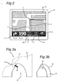
- Figure 2 depicts a navigation device 10 as described above.
- Navigator software when running on the navigation device 10, causes a navigation device 10 to display a normal navigation mode screen at the display 18, as shown in Fig. 2 .
- This view may provide driving instructions using a combination of text, symbols, voice guidance and a moving map.
- Key user interface elements are the following: a 3-D map occupies most of the screen. It is noted that the map may also be shown as a 2-D map.
- the map shows the position of the navigation device 10 and its immediate surroundings, rotated in such a way that the direction in which the navigation device 10 is moving is always "up".
- Running across the bottom quarter of the screen may be a status bar 2.
- the current location of the navigation device 10 (as the navigation device 10 itself determines using conventional GPS location finding) and its orientation (as inferred from its direction of travel) is depicted by a position arrow 3.
- a route 4 calculated by the device (using route calculation algorithms stored in memory devices 11, 12, 13, 14, 15 as applied to map data stored in a map database in memory devices 11, 12, 13, 14, 15) is shown as darkened path.
- all major actions e.g. turning corners, crossroads, roundabouts etc.
- arrows 5 overlaying the route 4.
- the status bar 2 also includes at its left hand side a schematic icon depicting the next action 6 (here, a right turn).
- the status bar 2 also shows the distance to the next action (i.e. the right turn - here the distance is 50 meters) as extracted from a database of the entire route calculated by the device (i.e. a list of all roads and related actions defining the route to be taken).
- Status bar 2 also shows the name of the current road 8, the estimated time before arrival 9 (here 2 minutes and 40 seconds), the actual estimated arrival time 25 (11.36am) and the distance to the destination 26 (1.4Km).
- the status bar 2 may further show additional information, such as GPS signal strength in a mobile-phone style signal strength indicator.
- the navigation device may comprise input devices, such as a touch screen, that allows the users to call up a navigation menu (not shown). From this menu, other navigation functions can be initiated or controlled. Allowing navigation functions to be selected from a menu screen that is itself very readily called up (e.g. one step away from the map display to the menu screen) greatly simplifies the user interaction and makes it faster and easier.
- the navigation menu includes the option for the user to input a destination.
- the actual physical structure of the navigation device 10 itself may be fundamentally no different from any conventional handheld computer, other than the integral GPS receiver 23 or a GPS data feed from an external GPS receiver.
- memory devices 12, 13, 14, 15 store the route calculation algorithms, map database and user interface software;
- a processor unit 12 interprets and processes user input (e.g. using a touch screen to input the start and destination addresses and all other control inputs) and deploys the route calculation algorithms to calculate the optimal route.
- 'Optimal' may refer to criteria such as shortest time or shortest distance, or some other user-related factors.
- the user inputs his start position and required destination into the navigation software running on the navigation device 10, using the input devices provided, such as a touch screen 18, keyboard 16 etc.
- the user selects the manner in which a travel route is calculated: various modes are offered, such as a 'fast' mode that calculates the route very rapidly, but the route might not be the shortest; a 'full' mode that looks at all possible routes and locates the shortest, but takes longer to calculate etc.
- Other options are possible, with a user defining a route that is scenic - e.g. passes the most POI (points of interest) marked as views of outstanding beauty, or passes the most POIs of possible interest to children or uses the fewest junctions etc.
- Roads themselves are described in the map database that is part of navigation software (or is otherwise accessed by it) running on the navigation device 10 as lines - i.e. vectors (e.g. start point, end point, direction for a road, with an entire road being made up of many hundreds of such sections, each uniquely defined by start point/end point direction parameters).
- a map is then a set of such road vectors, plus points of interest (POIs), plus road names, plus other geographic features like park boundaries, river boundaries etc, all of which are defined in terms of vectors. All map features (e.g. road vectors, POIs etc.) are defined in a co-ordinate system that corresponds or relates to the GPS co-ordinate system, enabling a device's position as determined through a GPS system to be located onto the relevant road shown in a map.
- Route calculation uses complex algorithms that are part of the navigation software.
- the algorithms are applied to score large numbers of potential different routes.
- the navigation software then evaluates them against the user defined criteria (or device defaults), such as a full mode scan, with scenic route, past museums, and no speed camera.
- the route which best meets the defined criteria is then calculated by the processor unit 11 and then stored in a database in the memory devices 12, 13, 14, 15 as a sequence of vectors, road names and actions to be done at vector end-points (e.g. corresponding to pre-determined distances along each road of the route, such as after 100 meters, turn left into street x).
- Navigation device 10 may be separable from a docking system. As a result of its separability, the navigation device 10 may be disconnected from the docking system, which is e.g. located in a vehicle, and connected to another docking system at a different location, e.g. at a desk while being connected to a desktop computer.
- the docking system may comprise a power supply or a network connection.
- the navigation device 10 may be powered, or, in case the navigation device 10 itself comprises a power unit, such a unit may be "refilled”.
- the connection of navigation device 10 and the docking system may provide a network connection, like a connection to the Internet.
- Figures 3a-e schematically depict a first concept of connecting according to embodiments of the present invention.
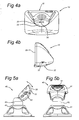
- Figures 3a and 3b schematically depict cross sectional views of a receiving part 30 of navigation device 10 and an extending part 31 of a docking system respectively when these two structures are not connected.
- a material that may be used for a chassis of the navigation device 10 is an aluminum alloy.
- the docking system may be constructed from polycarbonate-acrylonitrile butadiene styrene (PC-ABS) plastic.
- PC-ABS polycarbonate-acrylonitrile butadiene styrene
- navigation device 10 comprises a body provided with a receiving part 30, i.e. a cavity 32.
- the cavity has an inner surface provided with a connecting element 33.
- the extending part 31 comprises a connecting element 34.
- Connecting element 33 and connecting element 34 are complementary, i.e. connecting elements 33, 34 are arranged to connect with each other.
- connecting element 33 is of a male connecting type
- connecting element 34 in figures 3b-e is of a female connecting type.
- connection type is preferred in a vehicle environment for safety reasons.
- the docking system may be present in a vehicle without navigation device connected to it. To minimize risks regarding injuries, that are caused by extending structures or parts thereof, sharp edges or the like need to be avoided as much as possible.
- a connecting element of a female connection type does not extend into space as pronounced as does a connecting element of a male connection type.
- the extending part 31 of the docking system comprises a guiding outer surface 35.
- the cavity 32 of the navigation device 10 has an inner surface complimentary to the guiding outer surface 35 of the docking system.
- the guiding outer surface 35 of the docking system has a convex shape and the inner surface of the cavity 32 of the navigation device 10 has a concave shape.
- Figure 3c schematically depicts both navigation device 10 and extending part 31 of the docking system at a stage during connecting connecting elements 33, 34 with each other.
- part of the inner shape slides along a trajectory over the extending part 31 of the docking system while in contact with the guiding outer surface 35.
- connecting element 33 is guided towards connecting element 34 for connection.
- the trajectory is determined by the shape of the inner surface of the cavity 32 of the navigation device 10 together with the complimentary shape of the guiding outer surface 35 of the docking system.
- the extending part 31 has a radius larger than 2,5 mm to comply with requirements of some European automotive legislation.
- Figure 3d schematically depicts the situation when the navigation device 10 is almost connected to the docking system.
- the cavity 32 is now almost entirely occupied by the extending part 31 of the docking system:
- the connecting element 33 connects substantially in line with the connecting element 34.
- Both connecting elements 33, 34 are, at the time they come together, in the same plane.
- connecting element 33 may be provided with at least one guiding post (not shown). Even if the navigation device 10 is connected to the docking system under unstable conditions, e.g. in a moving car on a bumpy road, the navigation device 10 can be connected to the docking system without damaging the connecting elements 33,34.
- figure 3e schematically depicts a connected assembly of navigation device 10 and the extending part 31 of the docking system.
- the inner surface of the cavity 32 of the navigation device 10 and the guiding outer surface of the extending part 31 of the docking system may be precisely engineered to allow enough room for material expansion and contraction, while still allowing an uncomplicated docking procedure.
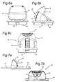
- FIGs 4a, 4b schematically depict a bottom and side view respectively of a navigation device 10 arranged for connection in accordance with the connecting concept depicted in figures 3a-e .
- the cavity 32 is depicted with dashed lines.
- the connecting element 33 shows four connection pins 36, it must be understood that this number is arbitrary.
- Connecting element 33 may comprise more or less connection pins 36 or, in case of a female type connecting element 33, connection holes.
- FIGS 5a, 5b schematically depict a side and front view respectively of a docking system 40 according to an embodiment arranged for disjoinable attachment to a substantially flat surface (not shown), e.g. a car window.
- the docking system 40 of this embodiment comprises a suction cup 41.
- the extending part 31 of the docking system 40 may be pivotably mounted on a supporting structure, i.e. directly on the suction cup 41 or on a standard 42 that, if present, is connected with the suction cup 41.
- the pivoting ability of the extending part 31 enables a user to adjust the orientation of the navigation system after connection of the navigation device 10 with the docking system 40.
- the extending part 31 is mounted on a standard 42 further adjustment of the orientation of the navigation system may be achieved by pivotably connecting the standard 42 to the suction cup 41.
- the adjustments enable the user to optimize the orientation of the display 18 of the navigation device 10.
- the connections between extending part 31 and standard 42 as well as between standard 42 and suction cup 41 or the connection between extending part 31 and suction cup 41 may be fixable with fixation elements like screws 43 or the like.
- Figure 6a schematically depicts a schematic view of a docking system according to an embodiment arranged for integration in a substantially flat surface, e.g. a dashboard of a vehicle, in a "closed” position.
- Figures 6b, 6c schematically depict a side and front view respectively of the docking system depicted in figure 6a in an "open" position.
- the extending part 31 of the docking system 40 is pivotably mounted on a supporting structure 45.
- the supporting structure 45 is again arranged to be disjoinably connected to the substantially flat surface (not shown), such that it fits in a suitable recess therein.
- the supporting structure 45 may comprise at least one click spring 46.
- the extending part 31 of the docking system 40 In the "closed" position, depicted in figure 6a , only the extending part 31 of the docking system 40 according to this embodiment extends from the substantially flat surface. However, in order to connect the navigation device 10 with the docking system 40, more space may be needed. Therefore, the extending part 31 of the docking system 40 may fold out towards an "open" position, i.e. the position depicted in figures 6b, 6c . A trajectory between aforementioned two positions may be mechanically controlled by a foldout-guiding element 47. To prevent random movement between the "closed" and “open” position, for instance due to instantaneous acceleration or braking of a vehicle, the extending part 31 may be fixed in these positions in ways known to persons skilled in the art, e.g. a locking mechanism.
- the docking system 40 In case the navigation device 10 is not connected to the docking system 40, the docking system 40 is preferably in its "closed" position. In this position, only a relatively small portion of the docking system 40 extends into the surrounding environment. Safety issues encourage an absence of such extending portions and/or elements as much as possible.
- FIGS 7a, 7b schematically depicts a side and front view respectively of a docking system 40 according to an embodiment arranged for connection to an external terminal (not shown), e.g. a desktop computer.
- the extending part 31 of the docking system 40 is mounted on a supporting structure 50.
- the supporting substrate 50 may be fixable on a flat surface (not shown), e.g. a desk, but may also just rest on this surface.
- the dockings system 40 may be arranged to accommodate a cable 51 in a way known to persons skilled in the art for connecting the docking system 40 to an external device, e.g. desktop computer.
- FIGS 8a, 8b, 8c schematically depict a second concept of connecting according to embodiments of the present invention.
- a navigation device 10 and an extending part 31 of a docking system are connected by using the guiding outer surface 35 of the extending part 31 as depicted in figure 8a to establish a connection between connecting elements 33, 34 as shown in figure 8c .
- this second concept of connecting use is made of an additional recess or undercut 62 besides the connecting element 33 of the navigation device 10.
- the additional recess 62 ensures that the connecting elements 33, 34 are held clear from each other until it is engaged by the extending part 31 of the docking system. It minimizes the risk of damage to connecting elements 33, 34.
- the navigation device 10 may be provided with a buffer element 60, for instance a rubber buffer element.
- the recess of navigation device 10 is different in orientation from recess 32 in figure 4b . It must be understood that an orientation as shown in figures 8a-c may also be applied to a recess 32, i.e. a recess without an additional recess 62. Additionally, the recess with an additional recess 62 as shown in figures 8a-8c may also be oriented in the way as shown in figure 4b .
- the navigation device 10 may be connected to different types of docking systems 40. It is thus for instance possible to use the navigation device 10 in a vehicle, for instance by using the embodiment depicted in figures 5a, 5b , disconnect the navigation device 10 upon arrival at a destination and consecutively connect the navigation device 10 to the docking system 40 as depicted in figures 7a, 7b for planning a new route in cooperation with an external device, e.g. a desktop computer. Due to the guiding outer surface 35 of the extending part 31 of the docking systems 40, the connecting elements 33, 34 in the navigation device 10 and docking systems 40 respectively endure a minimum deterioration as a result of regular (dis)connections of the two structures 10, 40.
- a retractable peg may be of a door latch/lock type, i.e. a retractable/sliding peg on a door which engages with a hole in a door jam, preventing the door from rotating around its hinges.
- the peg may engages through the curved surfaces of both structures 10, 40. In this way, for instance a bumpy road has a minimum effect on the engagement of the two connecting elements 33, 34.
- the invention may take the form of a computer program containing one or more sequences of machine-readable instructions describing a method as disclosed above, or a data storage medium (e.g. semiconductor memory, magnetic or optical disk) having such a computer program stored therein. It will be understood by a skilled person that all software components may also be formed as hardware components.
Landscapes
- Engineering & Computer Science (AREA)
- Radar, Positioning & Navigation (AREA)
- Remote Sensing (AREA)
- Automation & Control Theory (AREA)
- Physics & Mathematics (AREA)
- General Physics & Mathematics (AREA)
- Navigation (AREA)
- Burglar Alarm Systems (AREA)
Claims (12)
- Navigationssystem zum Bereitstellen von Navigationsanweisungen, Folgendes umfassend:- ein Navigationsgerät (10), umfassend einen Körper, der mit einem aufnehmenden Teil (30) ausgestattet ist, der an einer Innenfläche mit einem Verbindungselement einer ersten Verbindungsart (33) ausgestattet ist,- ein Andocksystem (40), das zum Aufnehmen des Navigationsgeräts (10) gestaltet ist, wobei das Andocksystem (40) einen hervorstehenden Teil (31) umfasst, der mit einem Verbindungselement einer zweiten Verbindungsart (34) ausgestattet ist, wobei das Verbindungselement der zweiten Verbindungsart (34) zur Verbindung mit dem Verbindungselement der ersten Verbindungsart (33) gestaltet ist,
wobei der hervorstehende Teil (31) eine Außenfläche (35) mit einer Form umfasst, die der Innenfläche des aufnehmenden Teils (30) des Navigationsgeräts (10) zumindest teilweise im Wesentlichen ähnelt und der aufnehmende Teil (30) entlang einer Bewegungsbahn über die Außenfläche (35) gleiten kann, wobei die Bewegungsbahn durch die Form sowohl der Innenfläche des aufnehmenden Teils (30) des Navigationsgeräts (10) als auch der Außenfläche (35) des hervorstehenden Teils (31) des Andocksystems (40) bestimmt ist und wobei die Bewegungsbahn derart gestaltet ist, dass das Verbindungselement der ersten Verbindungsart (33) zwecks Verbindung zum Verbindungselement der zweiten Verbindungsart (34) geführt wird. - Navigationssystem nach Anspruch 1, wobei die Außenfläche (35) eine konvexe Form aufweist und die Innenfläche des aufnehmenden Teils (30) der Navigationsgeräts (10) eine konkave Form aufweist.
- Navigationssystem nach Anspruch 1 oder 2, wobei das Verbindungselement der ersten Verbindungsart (33) ein Steck-Verbindungselement ist und das Verbindungselement der zweiten Verbindungsart (34) ein Buchsen-Verbindungselement ist.
- Navigationssystem nach einem der Ansprüche 1 bis 3, wobei das Andocksystem (40) eine Tragstruktur (41, 42, 45, 50) umfasst und der hervorstehende Teil des Andocksystems schwenkbar auf der Tragstruktur (41, 42, 45, 50) montiert ist.
- Navigationssystem nach Anspruch 4, wobei die Tragstruktur (41, 42, 45, 50) einen Saugnapf (41) zum Anordnen einer lösbaren Verbindung mit einer im Wesentlichen flachen Oberfläche umfasst.
- Navigationssystem nach Anspruch 4, wobei die Tragstruktur (41, 42, 45, 50) mindestens eine Rastfeder (46) zum Anordnen einer lösbaren Verbindung mit einer im Wesentlichen flachen Oberfläche umfasst.
- Navigationssystem nach Anspruch 4, wobei die Tragstruktur (41, 42, 45, 50) zum Aufnehmen eines Kabels (51) gestaltet ist.
- Armaturenbrett, umfassend ein Andocksystem (40), das für ein Navigationssystem (10) nach einem der vorhergehenden Ansprüche geeignet ist.
- Fahrzeug, umfassend ein Navigationssystem nach einem der Ansprüche 1 bis 7.
- Navigationsgerät (10), das zur Verwendung in einem Navigationssystem nach einem der Ansprüche 1 bis 7 geeignet ist.
- Andocksystem (40), das zur Verwendung in einem Navigationssystem nach einem der Ansprüche 1 bis 7 geeignet ist.
- Verfahren zum Bilden eines Navigationssystems, wobei das Verfahren Folgendes umfasst:- Bereitstellen eines Navigationsgeräts (10), das einen Körper umfasst, der mit einem aufnehmenden Teil (30) ausgestattet ist, der an einer Innenfläche mit einem Verbindungselement einer ersten Verbindungsart (33) ausgestattet ist,- Bereitstellen eines Andocksystems (40), das zum Aufnehmen des Navigationsgeräts (10) gestaltet ist, wobei das Andocksystem (40) einen hervorstehenden Teil (31) umfasst, der mit einem Verbindungselement einer zweiten Verbindungsart (34) ausgestattet ist, wobei das Verbindungselement der zweiten Verbindungsart (34) zur Verbindung mit dem Verbindungselement der ersten Verbindungsart (33) gestaltet ist und der hervorstehende Teil (31) eine Außenfläche (35) mit einer Form umfasst, die der Innenfläche des aufnehmenden Teils (30) des Navigationsgeräts (10) zumindest teilweise im Wesentlichen ähnelt,- Gleitenlassen des aufnehmenden Teils (30) entlang einer Bewegungsbahn über die Außenfläche (35), wobei die Bewegungsbahn durch die Form sowohl der Innenfläche des aufnehmenden Teils (30) des Navigationsgeräts (10) als auch der Außenfläche (35) des hervorstehenden Teils (31) des Andocksystems (40) bestimmt ist und wobei die Bewegungsbahn derart gestaltet ist, dass das Verbindungselement der ersten Verbindungsart (33) zwecks Verbindung zum Verbindungselement der zweiten Verbindungsart (34) geführt wird.
Applications Claiming Priority (1)
| Application Number | Priority Date | Filing Date | Title |
|---|---|---|---|
| PCT/NL2006/050041 WO2007100239A1 (en) | 2006-02-28 | 2006-02-28 | Navigation system and method of forming a navigation system |
Publications (2)
| Publication Number | Publication Date |
|---|---|
| EP1999433A1 EP1999433A1 (de) | 2008-12-10 |
| EP1999433B1 true EP1999433B1 (de) | 2012-08-08 |
Family
ID=37106908
Family Applications (1)
| Application Number | Title | Priority Date | Filing Date |
|---|---|---|---|
| EP06716674A Expired - Lifetime EP1999433B1 (de) | 2006-02-28 | 2006-02-28 | Navigationssystem und verfahren zur bildung eines navigationssystems |
Country Status (9)
| Country | Link |
|---|---|
| US (1) | US7827341B2 (de) |
| EP (1) | EP1999433B1 (de) |
| JP (1) | JP4685941B2 (de) |
| CN (1) | CN101365926B (de) |
| AU (1) | AU2006339461A1 (de) |
| BR (1) | BRPI0621403A2 (de) |
| CA (1) | CA2641630A1 (de) |
| ES (1) | ES2388873T3 (de) |
| WO (1) | WO2007100239A1 (de) |
Families Citing this family (8)
| Publication number | Priority date | Publication date | Assignee | Title |
|---|---|---|---|---|
| US8218306B2 (en) * | 2007-09-04 | 2012-07-10 | Apple Inc. | Assembly of a handheld electronic device |
| DE602007006526D1 (de) | 2007-12-12 | 2010-06-24 | Bury Sp Zoo | Halter für ein tragbares elektronisches Gerät, speziell für ein Fahrzeugarmaturenbrett |
| DE102009025276B4 (de) | 2008-08-13 | 2010-10-14 | Navigon Ag | Befestigungsvorrichtung zur lösbaren Befestigung eines transportablen elektronischen Geräts |
| US8880332B2 (en) * | 2008-09-10 | 2014-11-04 | Toshiba Global Commerce Solutions Holdings Corporation | People guidance using kiosk and user ID |
| US9140719B2 (en) * | 2010-09-16 | 2015-09-22 | Pioneer Corporation | Terminal holding device |
| WO2013058678A1 (ru) | 2011-10-19 | 2013-04-25 | Ikonomov Artashes Valer Evich | Устройство для управления данными пользователя сети |
| US10115084B2 (en) | 2012-10-10 | 2018-10-30 | Artashes Valeryevich Ikonomov | Electronic payment system |
| US10114373B2 (en) * | 2016-05-17 | 2018-10-30 | Telenav, Inc. | Navigation system with trajectory calculation mechanism and method of operation thereof |
Family Cites Families (8)
| Publication number | Priority date | Publication date | Assignee | Title |
|---|---|---|---|---|
| JP3628424B2 (ja) * | 1996-04-09 | 2005-03-09 | 株式会社オートネットワーク技術研究所 | 車載用ディスプレイ装置 |
| US7853404B2 (en) | 2001-04-03 | 2010-12-14 | Mitac International Corporation | Vehicle docking station for portable handheld computing device |
| GB0405794D0 (en) | 2004-03-15 | 2004-04-21 | Tomtom Bv | Dock for a portable navigation device |
| US7515709B2 (en) * | 2004-10-26 | 2009-04-07 | Harald Richter | Modular apparatus holder with multipurpose intermediate support member for supporting minicomputers, cell phones and similar apparatus |
| DE102005011215B4 (de) * | 2005-03-09 | 2006-12-07 | Bury Sp.Z.O.O | Navigationsanlage |
| US20080021634A1 (en) * | 2005-12-27 | 2008-01-24 | Diaz Melvin B | Latch apparatus for portable electronic devices |
| US7869196B2 (en) * | 2006-12-28 | 2011-01-11 | Fujitsu Ten Limited | Electronic apparatus |
| DE602007006526D1 (de) * | 2007-12-12 | 2010-06-24 | Bury Sp Zoo | Halter für ein tragbares elektronisches Gerät, speziell für ein Fahrzeugarmaturenbrett |
-
2006
- 2006-02-28 CN CN2006800516748A patent/CN101365926B/zh not_active Expired - Fee Related
- 2006-02-28 AU AU2006339461A patent/AU2006339461A1/en not_active Abandoned
- 2006-02-28 ES ES06716674T patent/ES2388873T3/es not_active Expired - Lifetime
- 2006-02-28 WO PCT/NL2006/050041 patent/WO2007100239A1/en not_active Ceased
- 2006-02-28 US US12/223,521 patent/US7827341B2/en not_active Expired - Lifetime
- 2006-02-28 BR BRPI0621403-7A patent/BRPI0621403A2/pt not_active IP Right Cessation
- 2006-02-28 CA CA002641630A patent/CA2641630A1/en not_active Abandoned
- 2006-02-28 JP JP2008557223A patent/JP4685941B2/ja not_active Expired - Fee Related
- 2006-02-28 EP EP06716674A patent/EP1999433B1/de not_active Expired - Lifetime
Also Published As
| Publication number | Publication date |
|---|---|
| ES2388873T3 (es) | 2012-10-19 |
| JP4685941B2 (ja) | 2011-05-18 |
| CN101365926B (zh) | 2011-05-11 |
| US20090212181A1 (en) | 2009-08-27 |
| JP2009528536A (ja) | 2009-08-06 |
| BRPI0621403A2 (pt) | 2011-12-06 |
| EP1999433A1 (de) | 2008-12-10 |
| CN101365926A (zh) | 2009-02-11 |
| US7827341B2 (en) | 2010-11-02 |
| CA2641630A1 (en) | 2007-09-07 |
| AU2006339461A1 (en) | 2007-09-07 |
| WO2007100239A1 (en) | 2007-09-07 |
Similar Documents
| Publication | Publication Date | Title |
|---|---|---|
| EP1889007B1 (de) | Navigationseinrichtung mit kamera-info | |
| US20090070038A1 (en) | Navigation Device with Automatic Gps Precision Enhancement | |
| EP1910132B1 (de) | Halterung zur befestigung einer vorrichtung, wie zum beispiel einer telefongabel oder einer navigationsvorrichtung an einer fläche | |
| EP2032944A1 (de) | Navigationsgerät und verfahren zur bereitstellung von warnungen in bezug auf eine radarfalle | |
| US20090105947A1 (en) | Computer System and Method for Providing Warnings to a User for Completing Tasks From the Task List | |
| US20070150190A1 (en) | Gps navigation system | |
| US20090143980A1 (en) | Navigation Device and Method of Scrolling Map Data Displayed On a Navigation Device | |
| US7827341B2 (en) | Navigation system and method of forming a navigation system | |
| RU2391229C1 (ru) | Навигационная система и способ формирования навигационной системы | |
| HK1123354A (en) | Navigation system and method of forming a navigation system | |
| KR20080100817A (ko) | 네비게이션 시스템 및 네비게이션 시스템 형성 방법 | |
| JP2009294169A (ja) | 地図情報表示装置および地図情報表示方法 | |
| KR20090027187A (ko) | 업무리스트의 업무들을 완성하기 위해 사용자에게 경고를 제공하는 컴퓨터 시스템 및 방법 | |
| HK1115017A (en) | Mount for mounting a device, such as a telephone cradle or a navigation device, to a surface | |
| KR20080036039A (ko) | 내비게이션 기기 상에 표시된 지도 데이터를 스크롤하는내비게이션 기기 및 방법 | |
| HK1087462B (en) | Navigation device with touch screen | |
| HK1087462A1 (en) | Navigation device with touch screen | |
| NZ564320A (en) | Navigation device and method of scrolling map data displayed on a navigation device | |
| HK1114169A (en) | Navigation device and method of scrolling map data displayed on a navigation device |
Legal Events
| Date | Code | Title | Description |
|---|---|---|---|
| PUAI | Public reference made under article 153(3) epc to a published international application that has entered the european phase |
Free format text: ORIGINAL CODE: 0009012 |
|
| 17P | Request for examination filed |
Effective date: 20080619 |
|
| AK | Designated contracting states |
Kind code of ref document: A1 Designated state(s): AT BE BG CH CY CZ DE DK EE ES FI FR GB GR HU IE IS IT LI LT LU LV MC NL PL PT RO SE SI SK TR |
|
| RAP1 | Party data changed (applicant data changed or rights of an application transferred) |
Owner name: TOMTOM INTERNATIONAL B.V. |
|
| GRAP | Despatch of communication of intention to grant a patent |
Free format text: ORIGINAL CODE: EPIDOSNIGR1 |
|
| GRAS | Grant fee paid |
Free format text: ORIGINAL CODE: EPIDOSNIGR3 |
|
| GRAA | (expected) grant |
Free format text: ORIGINAL CODE: 0009210 |
|
| DAX | Request for extension of the european patent (deleted) | ||
| AK | Designated contracting states |
Kind code of ref document: B1 Designated state(s): AT BE BG CH CY CZ DE DK EE ES FI FR GB GR HU IE IS IT LI LT LU LV MC NL PL PT RO SE SI SK TR |
|
| REG | Reference to a national code |
Ref country code: GB Ref legal event code: FG4D |
|
| REG | Reference to a national code |
Ref country code: CH Ref legal event code: EP Ref country code: AT Ref legal event code: REF Ref document number: 570000 Country of ref document: AT Kind code of ref document: T Effective date: 20120815 |
|
| REG | Reference to a national code |
Ref country code: IE Ref legal event code: FG4D |
|
| REG | Reference to a national code |
Ref country code: NL Ref legal event code: T3 |
|
| REG | Reference to a national code |
Ref country code: DE Ref legal event code: R096 Ref document number: 602006031265 Country of ref document: DE Effective date: 20120927 |
|
| REG | Reference to a national code |
Ref country code: ES Ref legal event code: FG2A Ref document number: 2388873 Country of ref document: ES Kind code of ref document: T3 Effective date: 20121019 |
|
| REG | Reference to a national code |
Ref country code: AT Ref legal event code: MK05 Ref document number: 570000 Country of ref document: AT Kind code of ref document: T Effective date: 20120808 |
|
| REG | Reference to a national code |
Ref country code: LT Ref legal event code: MG4D Effective date: 20120801 |
|
| PG25 | Lapsed in a contracting state [announced via postgrant information from national office to epo] |
Ref country code: CY Free format text: LAPSE BECAUSE OF FAILURE TO SUBMIT A TRANSLATION OF THE DESCRIPTION OR TO PAY THE FEE WITHIN THE PRESCRIBED TIME-LIMIT Effective date: 20120808 Ref country code: LT Free format text: LAPSE BECAUSE OF FAILURE TO SUBMIT A TRANSLATION OF THE DESCRIPTION OR TO PAY THE FEE WITHIN THE PRESCRIBED TIME-LIMIT Effective date: 20120808 Ref country code: AT Free format text: LAPSE BECAUSE OF FAILURE TO SUBMIT A TRANSLATION OF THE DESCRIPTION OR TO PAY THE FEE WITHIN THE PRESCRIBED TIME-LIMIT Effective date: 20120808 Ref country code: FI Free format text: LAPSE BECAUSE OF FAILURE TO SUBMIT A TRANSLATION OF THE DESCRIPTION OR TO PAY THE FEE WITHIN THE PRESCRIBED TIME-LIMIT Effective date: 20120808 Ref country code: IS Free format text: LAPSE BECAUSE OF FAILURE TO SUBMIT A TRANSLATION OF THE DESCRIPTION OR TO PAY THE FEE WITHIN THE PRESCRIBED TIME-LIMIT Effective date: 20121208 |
|
| PG25 | Lapsed in a contracting state [announced via postgrant information from national office to epo] |
Ref country code: LV Free format text: LAPSE BECAUSE OF FAILURE TO SUBMIT A TRANSLATION OF THE DESCRIPTION OR TO PAY THE FEE WITHIN THE PRESCRIBED TIME-LIMIT Effective date: 20120808 Ref country code: PT Free format text: LAPSE BECAUSE OF FAILURE TO SUBMIT A TRANSLATION OF THE DESCRIPTION OR TO PAY THE FEE WITHIN THE PRESCRIBED TIME-LIMIT Effective date: 20121210 Ref country code: BE Free format text: LAPSE BECAUSE OF FAILURE TO SUBMIT A TRANSLATION OF THE DESCRIPTION OR TO PAY THE FEE WITHIN THE PRESCRIBED TIME-LIMIT Effective date: 20120808 Ref country code: GR Free format text: LAPSE BECAUSE OF FAILURE TO SUBMIT A TRANSLATION OF THE DESCRIPTION OR TO PAY THE FEE WITHIN THE PRESCRIBED TIME-LIMIT Effective date: 20121109 Ref country code: PL Free format text: LAPSE BECAUSE OF FAILURE TO SUBMIT A TRANSLATION OF THE DESCRIPTION OR TO PAY THE FEE WITHIN THE PRESCRIBED TIME-LIMIT Effective date: 20120808 Ref country code: SE Free format text: LAPSE BECAUSE OF FAILURE TO SUBMIT A TRANSLATION OF THE DESCRIPTION OR TO PAY THE FEE WITHIN THE PRESCRIBED TIME-LIMIT Effective date: 20120808 Ref country code: SI Free format text: LAPSE BECAUSE OF FAILURE TO SUBMIT A TRANSLATION OF THE DESCRIPTION OR TO PAY THE FEE WITHIN THE PRESCRIBED TIME-LIMIT Effective date: 20120808 |
|
| PG25 | Lapsed in a contracting state [announced via postgrant information from national office to epo] |
Ref country code: DK Free format text: LAPSE BECAUSE OF FAILURE TO SUBMIT A TRANSLATION OF THE DESCRIPTION OR TO PAY THE FEE WITHIN THE PRESCRIBED TIME-LIMIT Effective date: 20120808 Ref country code: EE Free format text: LAPSE BECAUSE OF FAILURE TO SUBMIT A TRANSLATION OF THE DESCRIPTION OR TO PAY THE FEE WITHIN THE PRESCRIBED TIME-LIMIT Effective date: 20120808 Ref country code: CZ Free format text: LAPSE BECAUSE OF FAILURE TO SUBMIT A TRANSLATION OF THE DESCRIPTION OR TO PAY THE FEE WITHIN THE PRESCRIBED TIME-LIMIT Effective date: 20120808 Ref country code: RO Free format text: LAPSE BECAUSE OF FAILURE TO SUBMIT A TRANSLATION OF THE DESCRIPTION OR TO PAY THE FEE WITHIN THE PRESCRIBED TIME-LIMIT Effective date: 20120808 |
|
| PG25 | Lapsed in a contracting state [announced via postgrant information from national office to epo] |
Ref country code: SK Free format text: LAPSE BECAUSE OF FAILURE TO SUBMIT A TRANSLATION OF THE DESCRIPTION OR TO PAY THE FEE WITHIN THE PRESCRIBED TIME-LIMIT Effective date: 20120808 |
|
| PLBE | No opposition filed within time limit |
Free format text: ORIGINAL CODE: 0009261 |
|
| STAA | Information on the status of an ep patent application or granted ep patent |
Free format text: STATUS: NO OPPOSITION FILED WITHIN TIME LIMIT |
|
| 26N | No opposition filed |
Effective date: 20130510 |
|
| PG25 | Lapsed in a contracting state [announced via postgrant information from national office to epo] |
Ref country code: BG Free format text: LAPSE BECAUSE OF FAILURE TO SUBMIT A TRANSLATION OF THE DESCRIPTION OR TO PAY THE FEE WITHIN THE PRESCRIBED TIME-LIMIT Effective date: 20121108 |
|
| REG | Reference to a national code |
Ref country code: DE Ref legal event code: R097 Ref document number: 602006031265 Country of ref document: DE Effective date: 20130510 |
|
| PG25 | Lapsed in a contracting state [announced via postgrant information from national office to epo] |
Ref country code: MC Free format text: LAPSE BECAUSE OF NON-PAYMENT OF DUE FEES Effective date: 20130228 |
|
| REG | Reference to a national code |
Ref country code: CH Ref legal event code: PL |
|
| PG25 | Lapsed in a contracting state [announced via postgrant information from national office to epo] |
Ref country code: LI Free format text: LAPSE BECAUSE OF NON-PAYMENT OF DUE FEES Effective date: 20130228 Ref country code: CH Free format text: LAPSE BECAUSE OF NON-PAYMENT OF DUE FEES Effective date: 20130228 |
|
| REG | Reference to a national code |
Ref country code: IE Ref legal event code: MM4A |
|
| PG25 | Lapsed in a contracting state [announced via postgrant information from national office to epo] |
Ref country code: IE Free format text: LAPSE BECAUSE OF NON-PAYMENT OF DUE FEES Effective date: 20130228 |
|
| PG25 | Lapsed in a contracting state [announced via postgrant information from national office to epo] |
Ref country code: TR Free format text: LAPSE BECAUSE OF FAILURE TO SUBMIT A TRANSLATION OF THE DESCRIPTION OR TO PAY THE FEE WITHIN THE PRESCRIBED TIME-LIMIT Effective date: 20120808 |
|
| PG25 | Lapsed in a contracting state [announced via postgrant information from national office to epo] |
Ref country code: HU Free format text: LAPSE BECAUSE OF FAILURE TO SUBMIT A TRANSLATION OF THE DESCRIPTION OR TO PAY THE FEE WITHIN THE PRESCRIBED TIME-LIMIT; INVALID AB INITIO Effective date: 20060228 Ref country code: LU Free format text: LAPSE BECAUSE OF NON-PAYMENT OF DUE FEES Effective date: 20130228 |
|
| REG | Reference to a national code |
Ref country code: FR Ref legal event code: PLFP Year of fee payment: 11 |
|
| REG | Reference to a national code |
Ref country code: FR Ref legal event code: PLFP Year of fee payment: 12 |
|
| REG | Reference to a national code |
Ref country code: FR Ref legal event code: PLFP Year of fee payment: 13 |
|
| PGFP | Annual fee paid to national office [announced via postgrant information from national office to epo] |
Ref country code: GB Payment date: 20220106 Year of fee payment: 17 |
|
| PGFP | Annual fee paid to national office [announced via postgrant information from national office to epo] |
Ref country code: NL Payment date: 20220118 Year of fee payment: 17 Ref country code: IT Payment date: 20220111 Year of fee payment: 17 Ref country code: FR Payment date: 20220127 Year of fee payment: 17 Ref country code: ES Payment date: 20220303 Year of fee payment: 17 |
|
| PGFP | Annual fee paid to national office [announced via postgrant information from national office to epo] |
Ref country code: DE Payment date: 20230104 Year of fee payment: 18 |
|
| REG | Reference to a national code |
Ref country code: NL Ref legal event code: MM Effective date: 20230301 |
|
| GBPC | Gb: european patent ceased through non-payment of renewal fee |
Effective date: 20230228 |
|
| PG25 | Lapsed in a contracting state [announced via postgrant information from national office to epo] |
Ref country code: NL Free format text: LAPSE BECAUSE OF NON-PAYMENT OF DUE FEES Effective date: 20230301 |
|
| PG25 | Lapsed in a contracting state [announced via postgrant information from national office to epo] |
Ref country code: GB Free format text: LAPSE BECAUSE OF NON-PAYMENT OF DUE FEES Effective date: 20230228 |
|
| PG25 | Lapsed in a contracting state [announced via postgrant information from national office to epo] |
Ref country code: IT Free format text: LAPSE BECAUSE OF NON-PAYMENT OF DUE FEES Effective date: 20230228 Ref country code: GB Free format text: LAPSE BECAUSE OF NON-PAYMENT OF DUE FEES Effective date: 20230228 Ref country code: FR Free format text: LAPSE BECAUSE OF NON-PAYMENT OF DUE FEES Effective date: 20230228 |
|
| REG | Reference to a national code |
Ref country code: ES Ref legal event code: FD2A Effective date: 20240405 |
|
| PG25 | Lapsed in a contracting state [announced via postgrant information from national office to epo] |
Ref country code: ES Free format text: LAPSE BECAUSE OF NON-PAYMENT OF DUE FEES Effective date: 20230301 |
|
| PG25 | Lapsed in a contracting state [announced via postgrant information from national office to epo] |
Ref country code: ES Free format text: LAPSE BECAUSE OF NON-PAYMENT OF DUE FEES Effective date: 20230301 |
|
| REG | Reference to a national code |
Ref country code: DE Ref legal event code: R119 Ref document number: 602006031265 Country of ref document: DE |
|
| PG25 | Lapsed in a contracting state [announced via postgrant information from national office to epo] |
Ref country code: DE Free format text: LAPSE BECAUSE OF NON-PAYMENT OF DUE FEES Effective date: 20240903 |
|
| PG25 | Lapsed in a contracting state [announced via postgrant information from national office to epo] |
Ref country code: DE Free format text: LAPSE BECAUSE OF NON-PAYMENT OF DUE FEES Effective date: 20240903 |