EP1999856B1 - Système de station de base radio, noeud sur un réseau de communication mobile cellulaire et dispositif de séparation - Google Patents
Système de station de base radio, noeud sur un réseau de communication mobile cellulaire et dispositif de séparation Download PDFInfo
- Publication number
- EP1999856B1 EP1999856B1 EP06717130.6A EP06717130A EP1999856B1 EP 1999856 B1 EP1999856 B1 EP 1999856B1 EP 06717130 A EP06717130 A EP 06717130A EP 1999856 B1 EP1999856 B1 EP 1999856B1
- Authority
- EP
- European Patent Office
- Prior art keywords
- base station
- radio base
- antenna
- splitter
- splitter device
- Prior art date
- Legal status (The legal status is an assumption and is not a legal conclusion. Google has not performed a legal analysis and makes no representation as to the accuracy of the status listed.)
- Expired - Lifetime
Links
Images


Classifications
-
- H—ELECTRICITY
- H04—ELECTRIC COMMUNICATION TECHNIQUE
- H04W—WIRELESS COMMUNICATION NETWORKS
- H04W88/00—Devices specially adapted for wireless communication networks, e.g. terminals, base stations or access point devices
- H04W88/08—Access point devices
- H04W88/10—Access point devices adapted for operation in multiple networks, e.g. multi-mode access points
-
- H—ELECTRICITY
- H01—ELECTRIC ELEMENTS
- H01Q—ANTENNAS, i.e. RADIO AERIALS
- H01Q1/00—Details of, or arrangements associated with, antennas
- H01Q1/12—Supports; Mounting means
- H01Q1/22—Supports; Mounting means by structural association with other equipment or articles
- H01Q1/24—Supports; Mounting means by structural association with other equipment or articles with receiving set
- H01Q1/241—Supports; Mounting means by structural association with other equipment or articles with receiving set used in mobile communications, e.g. GSM
- H01Q1/246—Supports; Mounting means by structural association with other equipment or articles with receiving set used in mobile communications, e.g. GSM specially adapted for base stations
Definitions
- the present invention refers to a radio base station system for mobile communications, comprising a first antenna and at least a first, a second and a third radio base station, the first radio base station being connected to the first antenna.
- the invention also relates to a node in a cellular mobile communications network, as well as a splitter device for use in a radio base system.
- GSM global system for mobile telecommunications
- TDMA time division multiple access
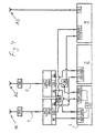
- Fig. 1 shows a known arrangement with a TDMA radio base station TDMA RBS, with two RX ports RXA, RXB and a TX port.
- the arrangement in fig. 1 can be a standalone TDMA 1900 MHz installation with tower mounted amplifiers TMA, which are powered with DC voltage overlaid on the feeder, for optimised receiver sensitivity.
- Fig. 2 shows a further example of a known arrangement.
- RX TDMA receive
- TX/RX transmit/receive
- Fig. 3 shows a known solution to introduce wide band code divisional multiple access (WCDMA) into existing sites.
- WCDMA wide band code divisional multiple access
- Two transmit/receive TX/RX ports of a WCDMA radio base station WCDMA RBS are connected to a respective master port of a respective diplex duplex unit DDU, which is a form of combiner.
- each diplex duplex unit has an antenna port ANT and a receive port RX and a slave port.
- Each diplex duplex unit forwards receive signals from the antenna port to the master port, forwards receive signals from the receive port RX to the slave port, and combines transmit TX signals on the master and slave ports to the common antenna port ANT.
- the WCDMA radio base station is provided with two co-siting ports RXB1, RXA1, each connected to the respective receive port RX of the respective diplex duplex unit DDU.
- the slave port of the respective diplex duplex unit DDU is connected to a respective transmit/receive TX/RX port of a GSM base station GSM RBS. Similar to the antenna sharing unit ASU in the GSM base station in fig.
- the WCDMA radio base station is equipped with functions for extracting receive signals and forwarding them to the GSM base station, via the diplex duplex units DDU.
- the GSM base station is provided with an antenna sharing unit ASU and a TMA simulator TMAS, extracts and forwards amplified receive signals to a slave TDMA radio base station TDMA RBS.
- the GSM radio base station will be a slave to the WCDMA base station, and the TDMA base station will in turn be slave to the slave GSM base station.
- a main drawback with the solution shown in fig. 3 is that a receiver of the TDMA base station will be last in a quite long chain with a series of successive alternating amplifications and attenuations, which affects the TDMA receiver sensitivity negatively. More specifically, an TDMA receive signal path will pass the antenna, the tower mounted amplifier TMA, which amplifies the signal, the diplex duplex unit feeder, which attenuates the signal, the WCDMA base station (amplification), a cable (attenuation), the GSM base station (amplification), and again a cable (attenuation), to arrive at the TDMA receiver.
- TMA the tower mounted amplifier
- Friis formula NR 1 + NR 2 - 1 g 1 + NR 3 - 1 g 1 ⁇ g 2 + NR 4 - 1 g 1 ⁇ g 2 ⁇ g 3 + .
- US 2003/0083072 A1 to Mostafa discloses a method for obtaining optimum RF performance for a slave base station when co-siting a master base station with said slave base station.
- the method involves calculating operating characteristics of the slave base station that is sharing an antenna assembly with the master base station.
- An object of the invention is to reduce the number of antennas needed in a cellular mobile communications network.
- Another object of the invention is to reduce the need for additional antennas when introducing a new technology in a cellular mobile communications network.
- a further object is to improve receiver sensitivity when at least three radio base stations share antennas.
- a radio base station system for mobile communications comprising a first antenna and at least a first, a second and a third radio base station, the first radio base station being connected to the first antenna. Further, the radio base station system comprises a first splitter device, which is connected to the first, the second and the third radio base station.
- the second and the third base stations are slaves that can be fed with receive signals in parallel from the first base station being a master.
- This provides a significantly shorter signal path for one of the slave base stations compared to the cascaded structure described above with reference to fig. 3 . This will significantly improve the receiver sensitivity of the slave base station.
- the radio base station system comprises a second antenna and a second splitter device, the first radio base station being connected to the second antenna, and the second splitter device being connected to the first, the second and the third radio base station.
- the first and second antenna in combination provides antenna diversity, i.e. information-carrying signals are transmitted along different propagation paths.
- the system provides antenna diversity in addition to the possibility for the second and the third base station slaves to receive the signals in parallel from the first base station master, regardless whether the signals were received by the first or the second antenna.
- the signal paths from both antennas are significantly shorter for one of the slave base stations, compared to the cascaded structure described above with reference to fig. 3 .
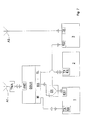
- Fig. 4 shows a radio base station system according to one embodiment of the invention, for cellular network mobile communications.
- the radio base station system comprises a first radio base station 1, in the form of a WCDMA base station 1, a second radio base station 2, in the form of a GSM radio base station 2, and a third base station 3, in the form of a TDMA base station 2, and a first antenna A1 for transmission and reception of radio signals.
- the first radio base station 1 is connected to the first antenna A1 via a first signal combining device DDU1, in the form of a diplex duplex unit, in itself known in the art.
- the first antenna A1 is connected, via a tower mounted amplifier TMA and a feeder F, to an antenna port ANT of the first signal combining device DDU1, and a first transmit and receive port TXRXA of the first base station 1 is connected to a master port M of the first signal combining device DDU1.
- the radio base station system comprises a first splitter device S1, described closer below with reference to fig. 5 and fig. 6 , which is connected to the first, the second, and the third radio base station 1, 2, 3.
- the latter is connected to the former via the first signal combining device DDU1.
- a first branch of the first splitter device S1 is connected to a first co-siting port RXA1 of the first base station 1.
- a second branch of the first splitter device S1 is connected to a receive port RX of the first signal combining device DDU1, and a slave port SL of the first signal combining device DDU1 is connected to a first transmit and receive port TXRXA of the second base station 2.
- a third branch of the first splitter device S1 is connected to a first receive port RXA of the third base station 3.
- the first branch of the splitter device S1 is also referred to as an input
- the second and third branches are also referred to as outputs.
- the first radio base station 1 comprises extraction means E to extract, from signals received by the first antenna A1, signals for the first radio base station 1.
- the extraction means E can comprise an antenna sharing unit (ASU), adapted to extract signals with a frequency for the first base station, and also to forward amplified signals.
- ASU antenna sharing unit
- the first signal combining device DDU1 is adapted to combine signals from the first and second radio base station 1, 2 for transmission by the first antenna A1. More specifically, transmit signals received by the master port M of the first signal combining device DDU1 from the first transmit and receive port TXRXA of the first base station 1, and transmit signals received by the slave port SL of the first signal combining device DDU1 from the first transmit and receive port TXRXA of the second base station 2, are combined by the first signal combining device DDU1 and received by the first antenna A1 via the antenna port ANT.
- the radio base station system comprises a second antenna A2 for transmission and reception of radio signals, connected to the base stations 1, 2, 3 in a manner corresponding to the manner in which the first antenna is incorporated.
- the second antenna A2 is connected, via a tower mounted amplifier TMA and a feeder F, to an antenna port ANT of a second signal combining device DDU2, and a second transmit and receive port TXRXB of the first base station 1 is connected to a master port M of the second signal combining device DDU2.
- a tower mounted amplifier TMA is provided.
- a first branch of a second splitter device S2 is connected to a second co-siting port RXB1 of the first base station 1.
- a second branch of the second splitter device S2 is connected to a receive port RX of the second signal combining device DDU2, and a slave port SL of the second signal combining device DDU2 is connected to a second transmit and receive port TXRXB of the second base station 2.
- a third branch of the second splitter device S2 is connected to a second receive port RXB of the third base station 3.
- the extraction means E of the first radio base station is adapted to extract, from signals received by the second antenna A2, signals for the first radio base station 1.
- a third antenna A3 is connected to a transmission port TX of the third base station 3.
- signals received by the first and second antenna A1, A2 pass the respective antenna ports ANT and master ports M, and are received at the first and second transmit and receive port TXRXA, TXRXB, respectively, of the first base station 1.
- the extraction means E in the first base station 1 extracts from the signals received, signals intended for the first base station.
- the signals received by the first and second antenna A1, A2 pass the first and second co-siting ports, RXA1, RXB1, respectively, of the first base station 1, and are received by the respective first branches of the first and second splitter devices S1, S2.
- the respective second branches of the splitter devices S1, S2 output the signals which are received by the respective receive ports RX of the first and second signal combining devices DDU1, DDU2, which feed them via the respective slave ports SL to the first and second transmit and receive ports TXRXA, TXRXB, respectively, of the second base station.
- the respective third branches of the splitter devices S1, S2 output the signals so that they are received by the first and second receive ports RXA, RXB, respectively, of the third base station.
- the second and third base station 2, 3 can comprise suitable means, for example comprising one or more filters, to extract from the signals received, signals intended for respective base stations.
- the concept of the embodiment of the invention shown in fig. 4 is to feed the slave GSM (second) radio base station 2, and slave TDMA (third) radio base station 3, with receive (RX) signals in parallel from the WCDMA master (first) radio base station 1. More generally, the invention will improve the resulting noise figure of the third radio base station 3 compared to the known solution described above with reference to fig. 3 .
- the receive signal path for the third base station 3 will be reduced to passing the antennas, the tower mounted amplifiers TMA (amplification), the feeders (attenuation), the first base station 1 (amplification), cables and splitter devices S1, S2 (attenuation), to a receiver in the third base station 3.
- the TDMA receive (RX) noise figure When introducing, in a manner according to the invention, a WCDMA base station to an arrangement with a GSM and a TDMA base station, as depicted in fig. 2 , the TDMA receive (RX) noise figure will remain essentially the same as before adding the WCDMA base station. It can easily be proven that the resulting TDMA receive (RX) noise figure will be improved by using the invention, compared to the known solution described above with reference to fig. 3 . The GSM noise figure will be unaffected since the splitter device S1, S2 loss can be seen as a part of the cable loss between the WCDMA base station and GSM base station, as long as sufficient gain is available from the WCDMA base station.
- the invention can be used in other co-siting applications, where a radio base station for a mobile communications standard different from WCDMA, e.g. GSM, TDMA or some other standard, is to be incorporated into an existing base station system.
- a radio base station for a mobile communications standard different from WCDMA e.g. GSM, TDMA or some other standard
- the first, second and third base stations as described above can be GSM, WCDMA and TDMA base stations, respectively, or TDMA, WCDMA and GSM base stations, respectively.
- the splitter devices S1, S2 can be equal splitters, which means that they provide the same power on both outputs, or unequal splitters, also known as tappers, which provide different power levels on the two outputs.
- the type of splitter devices used is preferably dependent on the required RF signal levels to the second and third base stations 2, 3.
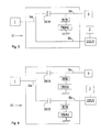
- a splitter device S1 to be used, as the first and second splitter devices S1, S2, in the radio base system according to the invention.
- the splitter devices S1, S2 can be standard splitters or tappers.
- the splitter device embodiments in fig. 5 and fig. 6 will improve the possibilities of adapting certain makes of TDMA radio base stations as slaves, in order for such base stations to enter the correct operational state, and to avoid short circuiting of DC voltage in the slave. More specifically, certain makes of TDMA radio base stations have a DC voltage on the receive port for a tower mounted amplifier in a traditional installation, and a DC current through the receive port is needed in order for the base station to operate correctly. When connecting such a receive port, according to the present invention, to a splitter device, the latter can be arranged as described below to avoid short circuiting of the DC voltage.
- a first branch Sa the splitter input, is connected to the first radio base station 1
- a second branch Sb one of the outputs, is connected to the second radio base station 2, via the first signal combining device DDU1, and a third branch Sc, the other output, is connected to the third radio base station 3.
- a simulation device TMAS adapted to simulate a tower mounted amplifier (TMA)
- TMA simulator TMAS is connected to the third branch and to ground.
- a DC current blocking device DCB is provided, for example in the form of a resistor, to prevent DC current from reaching the first branch and result in short circuiting.
- a RF blocking device RFB for example in the form of a low pass filter, is provided to direct signals from the antenna(s) to the third base station 3.
- a TMA simulator TMAS, DC current blocking device DCB, and a RF blocking device RFB are provided in a similar manner at the second branch Sb, as well.
- the TMA simulator TMAS provides a load that is at a level of the load that is provided by a tower mounted amplifier TMA for which the radio base station is adapted for. Providing a TMA simulator TMAS at a splitter device output Sb, Sc will solve the DC problem mentioned above, and the slave radio base station 2, 3 connected to the output will behave as if it has a tower mounted amplifier TMA connected to it.
- a DC block with a (TDMA) TMA simulator provided externally of a standard splitter or tapper can be used.
- two splitter devices S1, S2 (splitters or tappers), provided with TMA simulators TMAS can be integrated as one physical unit, which is advantageous from an installation point of view.
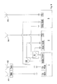
- fig. 7 shows an example of such a system, and it corresponds to the system in fig. 4 , with the difference that no second antenna A2, no second signal combining device DDU2, and no second splitter device S2 are provided.
- Fig. 8 shows an alternative embodiment of the invention.
- the radio base system in fig. 8 corresponds to the one described above with reference to fig. 4 , except for the following differences:
- the first and a second antenna A1, A2, for transmission and reception of radio signals, are connected to the first radio case station 1, without any interposed signal combining device. More specifically, the first and second antennas A1, A2 are connected to a first and second transmit and receive port TXRXA, TXRXB, respectively. Further, the first and the second splitter device S1, S2 are connected to the second base station 2, without any interposed signal combining device.
- a respective output of the first and the second splitter device S1, S2 are connected to a first and a second receive port RXA, RXB, respectively, of the second base station 2.
- a fourth antenna A4 is connected to a transmission port TX of the second base station 2.
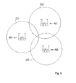
- Fig. 9 shows schematically a part of a cellular mobile communications network, with cells C1, C2, C3, in which radio coverage is provided by nodes N1, N2, N3, each comprising a radio base station system according to any of the embodiments described above.
Landscapes
- Engineering & Computer Science (AREA)
- Computer Networks & Wireless Communication (AREA)
- Signal Processing (AREA)
- Mobile Radio Communication Systems (AREA)
Claims (11)
- Système de station de base radio pour des communications mobiles, comprenant une première antenne (A1) et au moins une première, une deuxième et une troisième station de base radio (1, 2, 3), la première station de base radio (1) étant connectée à la première antenne (A1), comprenant en outre un premier dispositif de séparation (S1), la première station de base radio (1) étant connectée à une entrée (Sa) du premier dispositif de séparation (S1), dans lequel les deuxième et troisième stations de base radio (2, 3) sont connectées à une sortie respective (Sb, Sc) du premier dispositif de séparation (S1), ledit système étant caractérisé par une seconde antenne (A2) et un second dispositif de séparation (S2), la première station de base radio (1) étant connectée à la seconde antenne (A2), et le second dispositif de séparation (S2) étant connectée aux première, deuxième et troisième stations de base radio (1, 2, 3).
- Système de station de base radio selon la revendication 1, comprenant un premier dispositif de combinaison de signaux (DDU1), la première station de base radio (1) étant connectée à la première antenne (A1) par le biais du premier dispositif de combinaison de signaux (DDU1), et le premier dispositif de séparation (S1) étant connecté à la deuxième station de base radio (2) par le biais du premier dispositif de combinaison de signaux (DDU1).
- Système de station de base radio selon la revendication 2, dans lequel le premier dispositif de combinaison de signaux (DDU1) est apte à combiner des signaux provenant des première et deuxième stations de base radio (1, 2), devant être transmis par la première antenne (A1).
- Système de station de base radio selon l'une quelconque des revendications précédentes, comprenant des moyens d'extraction (E) aptes à extraire, à partir de signaux reçus par la première antenne (A1), des signaux pour la première station de base (1).
- Système de station de base radio selon l'une quelconque des revendications précédentes, comprenant un second dispositif de combinaison de signaux (DDU2), la première station de base radio (1) étant connectée à la seconde antenne (A2) par le biais du second dispositif de combinaison de signaux (DDU2), et le second dispositif de séparation (S2) étant connecté à la deuxième station de base radio (2) par le biais du second dispositif de combinaison de signaux (DDU2).
- Système de station de base radio selon l'une quelconque des revendications précédentes, dans lequel le second dispositif de combinaison de signaux (DDU2) est apte à combiner des signaux, provenant des première et deuxième stations de base radio (1, 2), devant être transmis par la première antenne (A1).
- Système de station de base radio selon l'une quelconque des revendications précédentes, dans lequel la première station de base radio (1) est connectée à une entrée (Sa) du second dispositif de séparation (S2), et les deuxième et troisième stations de base radio (2, 3) sont connectées à une sortie respective (Sb, Sc) du second dispositif de séparation (S2).
- Système de station de base radio selon l'une quelconque des revendications précédentes, dans lequel les moyens d'extraction (E) sont aptes à extraire, à partir de signaux reçus par la seconde antenne (A2), des signaux pour la première station de base radio (1).
- Système de station de base radio selon l'une quelconque des revendications précédentes, dans lequel le premier dispositif de séparation (S1) présente au moins deux sorties (Sb, Sc), au moins l'une des sorties (Sb, Sc) étant connectée à un dispositif de simulation (TMAS), apte à simuler un amplificateur monté sur une tour (TMA).
- Dispositif de séparation (S1, S2) destiné à être utilisé dans un système de base radio selon la revendication 9, dans lequel au moins l'une des sorties (Sb, Sc) est agencée de manière à être connectée à un dispositif de simulation (TMAS), apte à simuler un amplificateur monté sur une tour (TMA).
- Noeud dans un réseau de communication mobile cellulaire, comprenant un système de station de base radio selon l'une quelconque des revendications 1 à 8.
Applications Claiming Priority (1)
| Application Number | Priority Date | Filing Date | Title |
|---|---|---|---|
| PCT/SE2006/050046 WO2007111545A1 (fr) | 2006-03-28 | 2006-03-28 | Système de station radio de base, noeud dans un réseau de communication mobile cellulaire et dispositif de séparation |
Publications (3)
| Publication Number | Publication Date |
|---|---|
| EP1999856A1 EP1999856A1 (fr) | 2008-12-10 |
| EP1999856A4 EP1999856A4 (fr) | 2011-06-08 |
| EP1999856B1 true EP1999856B1 (fr) | 2015-08-26 |
Family
ID=38541394
Family Applications (1)
| Application Number | Title | Priority Date | Filing Date |
|---|---|---|---|
| EP06717130.6A Expired - Lifetime EP1999856B1 (fr) | 2006-03-28 | 2006-03-28 | Système de station de base radio, noeud sur un réseau de communication mobile cellulaire et dispositif de séparation |
Country Status (5)
| Country | Link |
|---|---|
| US (1) | US8078227B2 (fr) |
| EP (1) | EP1999856B1 (fr) |
| CN (1) | CN101406101A (fr) |
| CA (1) | CA2644611A1 (fr) |
| WO (1) | WO2007111545A1 (fr) |
Families Citing this family (11)
| Publication number | Priority date | Publication date | Assignee | Title |
|---|---|---|---|---|
| GB2444980B (en) | 2006-12-22 | 2012-02-22 | Deltenna Ltd | Antenna system |
| GB2483826B (en) * | 2006-12-22 | 2012-05-30 | Deltenna Ltd | Antenna system |
| CN101600269B (zh) * | 2009-06-30 | 2011-06-08 | 华为技术有限公司 | 一种天馈共享装置、系统及方法 |
| US8423028B2 (en) * | 2009-12-29 | 2013-04-16 | Ubidyne, Inc. | Active antenna array with multiple amplifiers for a mobile communications network and method of providing DC voltage to at least one processing element |
| US8731616B2 (en) * | 2009-12-29 | 2014-05-20 | Kathrein -Werke KG | Active antenna array and method for relaying first and second protocol radio signals in a mobile communications network |
| US8433242B2 (en) * | 2009-12-29 | 2013-04-30 | Ubidyne Inc. | Active antenna array for a mobile communications network with multiple amplifiers using separate polarisations for transmission and a combination of polarisations for reception of separate protocol signals |
| US9030363B2 (en) * | 2009-12-29 | 2015-05-12 | Kathrein-Werke Ag | Method and apparatus for tilting beams in a mobile communications network |
| US9054664B1 (en) | 2014-07-23 | 2015-06-09 | Wilson Electronics, Llc | Multiple-port signal boosters |
| JP6267250B2 (ja) * | 2016-02-25 | 2018-01-24 | 株式会社Subaru | 油圧回路の異常検知装置、及び、油圧回路の異常検知方法 |
| US10395542B2 (en) * | 2016-03-28 | 2019-08-27 | Cisco Technology, Inc. | Drone traffic engineering |
| EP3607671A1 (fr) | 2017-04-06 | 2020-02-12 | Wilson Electronics, LLC | Techniques pour configurer la puissance ou le gain d'un répéteur |
Family Cites Families (8)
| Publication number | Priority date | Publication date | Assignee | Title |
|---|---|---|---|---|
| US20010012788A1 (en) * | 1998-06-12 | 2001-08-09 | R. Keith Gammon | Pcs cell site system for allowing a plurality of pcs providers to share cell site antennas |
| US6366789B1 (en) * | 1999-03-29 | 2002-04-02 | Telefonaktiebolaget L M Ericsson (Publ) | Exploring radio base station configurations |
| EP1249946B1 (fr) * | 2001-04-11 | 2004-09-29 | Lucent Technologies Inc. | Circuit diviseur de signaux |
| US6925312B2 (en) * | 2001-09-17 | 2005-08-02 | Telefonaktiebolaget Lm Ericsson (Publ) | Sharing of antennas by base station nodes of telecommunications network |
| US6895247B2 (en) | 2001-11-01 | 2005-05-17 | Ericsson, Inc. | System and method for obtaining optimum RF performance when co-siting cellular base stations |
| US7120465B2 (en) | 2003-12-20 | 2006-10-10 | Telefonaktiebolaget Lm Ericsson (Publ) | Transceiver system including multiple radio base stations that share an antenna |
| WO2005088764A1 (fr) * | 2004-03-11 | 2005-09-22 | Telefonaktiebolaget Lm Ericsson (Publ) | Procede, dispositif, station de base et site permettant de reduire le nombre de lignes d'alimentation dans un systeme a diversite d'antenne |
| CN101002404B (zh) * | 2004-06-15 | 2012-12-12 | 艾利森电话股份有限公司 | 天线分集装置和方法 |
-
2006
- 2006-03-28 EP EP06717130.6A patent/EP1999856B1/fr not_active Expired - Lifetime
- 2006-03-28 US US12/293,698 patent/US8078227B2/en not_active Expired - Fee Related
- 2006-03-28 CA CA002644611A patent/CA2644611A1/fr not_active Abandoned
- 2006-03-28 WO PCT/SE2006/050046 patent/WO2007111545A1/fr not_active Ceased
- 2006-03-28 CN CNA2006800540215A patent/CN101406101A/zh active Pending
Also Published As
| Publication number | Publication date |
|---|---|
| US8078227B2 (en) | 2011-12-13 |
| US20090181722A1 (en) | 2009-07-16 |
| EP1999856A4 (fr) | 2011-06-08 |
| CN101406101A (zh) | 2009-04-08 |
| EP1999856A1 (fr) | 2008-12-10 |
| CA2644611A1 (fr) | 2007-10-04 |
| WO2007111545A1 (fr) | 2007-10-04 |
Similar Documents
| Publication | Publication Date | Title |
|---|---|---|
| KR100216349B1 (ko) | 코드분할다중접속 통신시스템의 전파중계장치 | |
| US8305941B2 (en) | Broadband combining system with high spectrum efficiency for use in wireless communications | |
| CN108233952B (zh) | 通信模块 | |
| US8078227B2 (en) | Radio base station system, a node in a cellular mobile communications network, and a splitter device | |
| EP3065317B1 (fr) | Combinateur/séparateur dans une même plage de fréquences et plate-forme de combinaison multi-systèmes | |
| US20220200690A1 (en) | Repeater system | |
| US5953659A (en) | Method and apparatus for producing delay of a carrier signal for implementing spatial diversity in a communications system | |
| US6993286B2 (en) | Dual band bidirectional amplifier for wireless communication | |
| EP3131214B1 (fr) | Multiplexeur, station de base, système multiplexeur de signaux et procédé d'émission de signaux | |
| US9048931B2 (en) | Method and arrangement for feeder sharing in a telecommunication system | |
| US9800301B2 (en) | Antenna sharing device for wireless access node systems in wireless communication network | |
| EP2892150B1 (fr) | Appareil d'amplification d'alimentation | |
| CN101414875B (zh) | 时分双工系统中对隧道进行覆盖的方法、设备和系统 | |
| EP0894372A1 (fr) | Repeteur a selection de canaux pour telephonie mobile | |
| EP3982545A1 (fr) | Appareil d'antenne duplex à répartition temporelle | |
| US20140354887A1 (en) | Method and system for antenna sharing | |
| GB2279504A (en) | Antenna system | |
| KR101182035B1 (ko) | 복수안테나를 구비한 원격 기지국 유닛 및 양방향 광 무선네트워크 | |
| EP1081878A2 (fr) | Répetiteur à une seule antenne et procédé de répétition d'un signal | |
| KR101506842B1 (ko) | Mimo 신호 확장 장치 | |
| CN116346152B (zh) | 一种天线系统和通信设备 | |
| CN118102320A (zh) | 一种基站 | |
| KR100957028B1 (ko) | 이동통신 중계기의 양방향 신호의 경로 단일화 회로장치 | |
| CN211879584U (zh) | 功率合成模块和功率合成电路 | |
| KR100784149B1 (ko) | 듀얼 타입 시분할 송수신 장치 |
Legal Events
| Date | Code | Title | Description |
|---|---|---|---|
| PUAI | Public reference made under article 153(3) epc to a published international application that has entered the european phase |
Free format text: ORIGINAL CODE: 0009012 |
|
| 17P | Request for examination filed |
Effective date: 20080924 |
|
| AK | Designated contracting states |
Kind code of ref document: A1 Designated state(s): AT BE BG CH CY CZ DE DK EE ES FI FR GB GR HU IE IS IT LI LT LU LV MC NL PL PT RO SE SI SK TR |
|
| A4 | Supplementary search report drawn up and despatched |
Effective date: 20110509 |
|
| 17Q | First examination report despatched |
Effective date: 20120614 |
|
| DAX | Request for extension of the european patent (deleted) | ||
| REG | Reference to a national code |
Ref country code: DE Ref legal event code: R079 Ref document number: 602006046426 Country of ref document: DE Free format text: PREVIOUS MAIN CLASS: H04B0001520000 Ipc: H01Q0001240000 |
|
| GRAP | Despatch of communication of intention to grant a patent |
Free format text: ORIGINAL CODE: EPIDOSNIGR1 |
|
| RIC1 | Information provided on ipc code assigned before grant |
Ipc: H04W 88/10 20090101ALI20150311BHEP Ipc: H01Q 1/24 20060101AFI20150311BHEP |
|
| INTG | Intention to grant announced |
Effective date: 20150401 |
|
| RAP1 | Party data changed (applicant data changed or rights of an application transferred) |
Owner name: TELEFONAKTIEBOLAGET L M ERICSSON (PUBL) |
|
| GRAS | Grant fee paid |
Free format text: ORIGINAL CODE: EPIDOSNIGR3 |
|
| GRAA | (expected) grant |
Free format text: ORIGINAL CODE: 0009210 |
|
| AK | Designated contracting states |
Kind code of ref document: B1 Designated state(s): AT BE BG CH CY CZ DE DK EE ES FI FR GB GR HU IE IS IT LI LT LU LV MC NL PL PT RO SE SI SK TR |
|
| REG | Reference to a national code |
Ref country code: GB Ref legal event code: FG4D |
|
| REG | Reference to a national code |
Ref country code: CH Ref legal event code: EP |
|
| REG | Reference to a national code |
Ref country code: AT Ref legal event code: REF Ref document number: 745660 Country of ref document: AT Kind code of ref document: T Effective date: 20150915 |
|
| REG | Reference to a national code |
Ref country code: IE Ref legal event code: FG4D |
|
| REG | Reference to a national code |
Ref country code: DE Ref legal event code: R096 Ref document number: 602006046426 Country of ref document: DE |
|
| REG | Reference to a national code |
Ref country code: AT Ref legal event code: MK05 Ref document number: 745660 Country of ref document: AT Kind code of ref document: T Effective date: 20150826 |
|
| REG | Reference to a national code |
Ref country code: LT Ref legal event code: MG4D |
|
| PG25 | Lapsed in a contracting state [announced via postgrant information from national office to epo] |
Ref country code: GR Free format text: LAPSE BECAUSE OF FAILURE TO SUBMIT A TRANSLATION OF THE DESCRIPTION OR TO PAY THE FEE WITHIN THE PRESCRIBED TIME-LIMIT Effective date: 20151127 Ref country code: LT Free format text: LAPSE BECAUSE OF FAILURE TO SUBMIT A TRANSLATION OF THE DESCRIPTION OR TO PAY THE FEE WITHIN THE PRESCRIBED TIME-LIMIT Effective date: 20150826 Ref country code: LV Free format text: LAPSE BECAUSE OF FAILURE TO SUBMIT A TRANSLATION OF THE DESCRIPTION OR TO PAY THE FEE WITHIN THE PRESCRIBED TIME-LIMIT Effective date: 20150826 Ref country code: FI Free format text: LAPSE BECAUSE OF FAILURE TO SUBMIT A TRANSLATION OF THE DESCRIPTION OR TO PAY THE FEE WITHIN THE PRESCRIBED TIME-LIMIT Effective date: 20150826 |
|
| REG | Reference to a national code |
Ref country code: NL Ref legal event code: MP Effective date: 20150826 |
|
| PG25 | Lapsed in a contracting state [announced via postgrant information from national office to epo] |
Ref country code: IS Free format text: LAPSE BECAUSE OF FAILURE TO SUBMIT A TRANSLATION OF THE DESCRIPTION OR TO PAY THE FEE WITHIN THE PRESCRIBED TIME-LIMIT Effective date: 20151226 Ref country code: ES Free format text: LAPSE BECAUSE OF FAILURE TO SUBMIT A TRANSLATION OF THE DESCRIPTION OR TO PAY THE FEE WITHIN THE PRESCRIBED TIME-LIMIT Effective date: 20150826 Ref country code: SE Free format text: LAPSE BECAUSE OF FAILURE TO SUBMIT A TRANSLATION OF THE DESCRIPTION OR TO PAY THE FEE WITHIN THE PRESCRIBED TIME-LIMIT Effective date: 20150826 Ref country code: AT Free format text: LAPSE BECAUSE OF FAILURE TO SUBMIT A TRANSLATION OF THE DESCRIPTION OR TO PAY THE FEE WITHIN THE PRESCRIBED TIME-LIMIT Effective date: 20150826 Ref country code: PL Free format text: LAPSE BECAUSE OF FAILURE TO SUBMIT A TRANSLATION OF THE DESCRIPTION OR TO PAY THE FEE WITHIN THE PRESCRIBED TIME-LIMIT Effective date: 20150826 Ref country code: PT Free format text: LAPSE BECAUSE OF FAILURE TO SUBMIT A TRANSLATION OF THE DESCRIPTION OR TO PAY THE FEE WITHIN THE PRESCRIBED TIME-LIMIT Effective date: 20151228 |
|
| PG25 | Lapsed in a contracting state [announced via postgrant information from national office to epo] |
Ref country code: NL Free format text: LAPSE BECAUSE OF FAILURE TO SUBMIT A TRANSLATION OF THE DESCRIPTION OR TO PAY THE FEE WITHIN THE PRESCRIBED TIME-LIMIT Effective date: 20150826 |
|
| PG25 | Lapsed in a contracting state [announced via postgrant information from national office to epo] |
Ref country code: EE Free format text: LAPSE BECAUSE OF FAILURE TO SUBMIT A TRANSLATION OF THE DESCRIPTION OR TO PAY THE FEE WITHIN THE PRESCRIBED TIME-LIMIT Effective date: 20150826 Ref country code: IT Free format text: LAPSE BECAUSE OF FAILURE TO SUBMIT A TRANSLATION OF THE DESCRIPTION OR TO PAY THE FEE WITHIN THE PRESCRIBED TIME-LIMIT Effective date: 20150826 Ref country code: SK Free format text: LAPSE BECAUSE OF FAILURE TO SUBMIT A TRANSLATION OF THE DESCRIPTION OR TO PAY THE FEE WITHIN THE PRESCRIBED TIME-LIMIT Effective date: 20150826 Ref country code: DK Free format text: LAPSE BECAUSE OF FAILURE TO SUBMIT A TRANSLATION OF THE DESCRIPTION OR TO PAY THE FEE WITHIN THE PRESCRIBED TIME-LIMIT Effective date: 20150826 Ref country code: CZ Free format text: LAPSE BECAUSE OF FAILURE TO SUBMIT A TRANSLATION OF THE DESCRIPTION OR TO PAY THE FEE WITHIN THE PRESCRIBED TIME-LIMIT Effective date: 20150826 |
|
| REG | Reference to a national code |
Ref country code: DE Ref legal event code: R097 Ref document number: 602006046426 Country of ref document: DE |
|
| PG25 | Lapsed in a contracting state [announced via postgrant information from national office to epo] |
Ref country code: RO Free format text: LAPSE BECAUSE OF FAILURE TO SUBMIT A TRANSLATION OF THE DESCRIPTION OR TO PAY THE FEE WITHIN THE PRESCRIBED TIME-LIMIT Effective date: 20150826 |
|
| PLBE | No opposition filed within time limit |
Free format text: ORIGINAL CODE: 0009261 |
|
| STAA | Information on the status of an ep patent application or granted ep patent |
Free format text: STATUS: NO OPPOSITION FILED WITHIN TIME LIMIT |
|
| PGFP | Annual fee paid to national office [announced via postgrant information from national office to epo] |
Ref country code: DE Payment date: 20160331 Year of fee payment: 11 |
|
| 26N | No opposition filed |
Effective date: 20160530 |
|
| PG25 | Lapsed in a contracting state [announced via postgrant information from national office to epo] |
Ref country code: BE Free format text: LAPSE BECAUSE OF NON-PAYMENT OF DUE FEES Effective date: 20160331 Ref country code: SI Free format text: LAPSE BECAUSE OF FAILURE TO SUBMIT A TRANSLATION OF THE DESCRIPTION OR TO PAY THE FEE WITHIN THE PRESCRIBED TIME-LIMIT Effective date: 20150826 |
|
| PG25 | Lapsed in a contracting state [announced via postgrant information from national office to epo] |
Ref country code: MC Free format text: LAPSE BECAUSE OF FAILURE TO SUBMIT A TRANSLATION OF THE DESCRIPTION OR TO PAY THE FEE WITHIN THE PRESCRIBED TIME-LIMIT Effective date: 20150826 Ref country code: LU Free format text: LAPSE BECAUSE OF FAILURE TO SUBMIT A TRANSLATION OF THE DESCRIPTION OR TO PAY THE FEE WITHIN THE PRESCRIBED TIME-LIMIT Effective date: 20160328 |
|
| REG | Reference to a national code |
Ref country code: CH Ref legal event code: PL |
|
| GBPC | Gb: european patent ceased through non-payment of renewal fee |
Effective date: 20160328 |
|
| REG | Reference to a national code |
Ref country code: IE Ref legal event code: MM4A |
|
| PG25 | Lapsed in a contracting state [announced via postgrant information from national office to epo] |
Ref country code: BE Free format text: LAPSE BECAUSE OF FAILURE TO SUBMIT A TRANSLATION OF THE DESCRIPTION OR TO PAY THE FEE WITHIN THE PRESCRIBED TIME-LIMIT Effective date: 20150826 |
|
| REG | Reference to a national code |
Ref country code: FR Ref legal event code: ST Effective date: 20161130 |
|
| PG25 | Lapsed in a contracting state [announced via postgrant information from national office to epo] |
Ref country code: LI Free format text: LAPSE BECAUSE OF NON-PAYMENT OF DUE FEES Effective date: 20160331 Ref country code: IE Free format text: LAPSE BECAUSE OF NON-PAYMENT OF DUE FEES Effective date: 20160328 Ref country code: FR Free format text: LAPSE BECAUSE OF NON-PAYMENT OF DUE FEES Effective date: 20160331 Ref country code: GB Free format text: LAPSE BECAUSE OF NON-PAYMENT OF DUE FEES Effective date: 20160328 Ref country code: CH Free format text: LAPSE BECAUSE OF NON-PAYMENT OF DUE FEES Effective date: 20160331 |
|
| REG | Reference to a national code |
Ref country code: DE Ref legal event code: R119 Ref document number: 602006046426 Country of ref document: DE |
|
| PG25 | Lapsed in a contracting state [announced via postgrant information from national office to epo] |
Ref country code: DE Free format text: LAPSE BECAUSE OF NON-PAYMENT OF DUE FEES Effective date: 20171003 |
|
| PG25 | Lapsed in a contracting state [announced via postgrant information from national office to epo] |
Ref country code: HU Free format text: LAPSE BECAUSE OF FAILURE TO SUBMIT A TRANSLATION OF THE DESCRIPTION OR TO PAY THE FEE WITHIN THE PRESCRIBED TIME-LIMIT; INVALID AB INITIO Effective date: 20060328 Ref country code: CY Free format text: LAPSE BECAUSE OF FAILURE TO SUBMIT A TRANSLATION OF THE DESCRIPTION OR TO PAY THE FEE WITHIN THE PRESCRIBED TIME-LIMIT Effective date: 20150826 |
|
| PG25 | Lapsed in a contracting state [announced via postgrant information from national office to epo] |
Ref country code: TR Free format text: LAPSE BECAUSE OF FAILURE TO SUBMIT A TRANSLATION OF THE DESCRIPTION OR TO PAY THE FEE WITHIN THE PRESCRIBED TIME-LIMIT Effective date: 20150826 |
|
| PG25 | Lapsed in a contracting state [announced via postgrant information from national office to epo] |
Ref country code: BG Free format text: LAPSE BECAUSE OF FAILURE TO SUBMIT A TRANSLATION OF THE DESCRIPTION OR TO PAY THE FEE WITHIN THE PRESCRIBED TIME-LIMIT Effective date: 20150826 |