EP2000064A1 - Vorrichtung zur Getränkeherstellung - Google Patents
Vorrichtung zur Getränkeherstellung Download PDFInfo
- Publication number
- EP2000064A1 EP2000064A1 EP07109590A EP07109590A EP2000064A1 EP 2000064 A1 EP2000064 A1 EP 2000064A1 EP 07109590 A EP07109590 A EP 07109590A EP 07109590 A EP07109590 A EP 07109590A EP 2000064 A1 EP2000064 A1 EP 2000064A1
- Authority
- EP
- European Patent Office
- Prior art keywords
- rocker arm
- main body
- housing
- pivoted
- secondary body
- Prior art date
- Legal status (The legal status is an assumption and is not a legal conclusion. Google has not performed a legal analysis and makes no representation as to the accuracy of the status listed.)
- Withdrawn
Links
- 239000002775 capsule Substances 0.000 claims abstract description 39
- 239000000126 substance Substances 0.000 claims abstract description 8
- XLYOFNOQVPJJNP-UHFFFAOYSA-N water Substances O XLYOFNOQVPJJNP-UHFFFAOYSA-N 0.000 claims abstract description 8
- 230000037431 insertion Effects 0.000 claims description 2
- 238000003780 insertion Methods 0.000 claims description 2
- 238000000605 extraction Methods 0.000 description 3
- 238000009835 boiling Methods 0.000 description 1
- 235000013353 coffee beverage Nutrition 0.000 description 1
- 235000015114 espresso Nutrition 0.000 description 1
- 230000005484 gravity Effects 0.000 description 1
- 239000000463 material Substances 0.000 description 1
- 238000002360 preparation method Methods 0.000 description 1
- 238000007789 sealing Methods 0.000 description 1
Images
Classifications
-
- A—HUMAN NECESSITIES
- A47—FURNITURE; DOMESTIC ARTICLES OR APPLIANCES; COFFEE MILLS; SPICE MILLS; SUCTION CLEANERS IN GENERAL
- A47J—KITCHEN EQUIPMENT; COFFEE MILLS; SPICE MILLS; APPARATUS FOR MAKING BEVERAGES
- A47J31/00—Apparatus for making beverages
- A47J31/40—Beverage-making apparatus with dispensing means for adding a measured quantity of ingredients, e.g. coffee, water, sugar, cocoa, milk, tea
- A47J31/407—Beverage-making apparatus with dispensing means for adding a measured quantity of ingredients, e.g. coffee, water, sugar, cocoa, milk, tea with ingredient-containing cartridges; Cartridge-perforating means
Definitions
- the present invention relates to an apparatus for preparing a drink of the type in which the drink is obtained by passing hot water in a single-dose capsule containing a substance to be extracted.
- All such apparatuses have a housing in which the capsule can be inserted and with which there are associated suitable means for injecting water into the capsule, as well as further means for allowing the drink to flow out (for example by piercing a wall of the capsule).
- the technical purpose which forms the basis of the present invention is to provide a new apparatus for preparing a drink which allows easy extraction of the capsule after use.
- the numeral 1 denotes as a whole an apparatus for preparing a drink by passing hot water in a capsule (belonging to the prior art and therefore not illustrated) containing a substance to be extracted, made in accordance with the present invention.
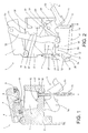
- the apparatus 1 comprises at least a main body 2 forming a housing 3 for a capsule containing the substance to be extracted, and at least a secondary body 4 associated with the main body 2 and which, in the embodiment illustrated, constitutes a lid for the housing 3.
- the secondary body 4 is pivoted at the main body 2 according to a horizontal axis of rotation, in such a way that the secondary body 4, in the open position, is rotated upwards relative to the closed position. It should be noticed that the in accompanying drawings the secondary body 4 is shown in an intermediate position between the open and closed positions.
- damper and sealing means inserted between the main body 2 and the secondary body 4 (ring-shaped seal 6 in Figure 1 ).
- the apparatus 1 also comprises means for making and dispensing the drink.
- the latter may take any form suitable for the purpose.
- the accompanying drawings associated with the housing 3 there are means for injecting hot water into the capsule, comprising a channel 7 lo terminating in a recess 8 extending around a first fixed spike 9 integral with the secondary body 4 and positioned in such a way that it projects into the housing 3, piercing the capsule when the housing 3 is closed.
- the channel 7 may also terminate in a first hollow spike 9, or there 1s may be two or more first spikes 9.
- Figure 1 shows a second fixed spike 10 integral with the base of the housing 3 and intended to pierce the base of the capsule. Suitable channels, not illustrated, allow the drink to flow out.
- the present invention may be applied irrespective of the structure of the means used to inject water into the capsule and to allow drink dispensing.
- the apparatus 1 comprises at least one pusher element 11 operatively associated with the housing 3 and able to move between a home position ( Figures 1 and 2 ) in which it allows a capsule to be positioned in the housing 3 and an operating position (not illustrated) in which it is able to act on a capsule inserted in the housing 3 to push it at least partly out of the housing 3.
- a home position Figures 1 and 2
- an operating position not illustrated
- movement means 12 ( Figure 2 ) designed at least to move the pusher element to the operating position.
- the pusher element 11 consists of a rigid rod 13 having an enlarged head 14 (which may be fixed or jointed to the rod 13), and which is inserted in a through-hole 15 that starts outside the main body 2 and ends with a counterbore 16 at the base of the housing 3. Said counterbore 16 houses the head 14 of the pusher element 11 when the latter is in the home position.
- hydraulic seal means which prevent the drink from flowing out of the main body 2 via the through-hole 15.
- the means 12 for moving the pusher element 11 may take different forms.
- the means 12 for moving the pusher element 11 are controlled directly by the manual movement means 5, in such a way that they move the pusher element 11 to the operating position when the main body 2 and the secondary body 4 are brought to the open position.
- the movement means 12 comprise at least one first rocker arm 17 with an intermediate portion pivoted at the main body 2 and by means of a first pin 18, and having a first end 19 and a second end 20.
- the first end 19 of the first rocker arm 17 is rotatably connected to the pusher element 11, whilst the second end 20 is operatively connected to a temporary hooking element 21.
- the first rocker arm 17 may rotate, relative to the main body 2, between a first position in which it holds the pusher element 11 in the home position ( Figures 1 and 2 ) and a second position in which it moves the pusher element 11 to the operating position (anti-clockwise rotation relative to the position illustrated in Figures 1 and 2 ).
- the temporary hooking element 21 is designed to be engaged by the manual movement means during the movement of the secondary body 4 from the closed position to the open position to cause the rotation of the first rocker arm 17, and to be released by the manual movement means when the secondary body 4 reaches the open position.
- the temporary hooking element 21 consists of a second rocker arm 22 with an intermediate portion pivoted, by means of a second pin 23, at the second end 20 of the first rocker arm 17.
- the second rocker arm 22 in turn has a first end 24 which can be operated by the manual movement means 5 and a second end 25 equipped with a stop element 26 designed to interact with the first rocker arm 17 as described below.
- the second rocker arm 22 can therefore move, relative to the first rocker arm 17, between a first position in which the stop element 26 rests on the first rocker arm 17 ( Figure 1 ), and a second position in which the stop element 26 is distanced from the first rocker arm 17 (position not illustrated but corresponding to a clockwise rotation of the second rocker arm 22 relative to the position illustrated in Figure 2 ).
- the movement means 12 also comprise at least one elastic return element 27 designed, in the absence of stresses, to hold the second rocker arm 22 in its first position and, consequently, the first rocker arm 17 in its first position.
- the elastic element 27 consists of a flat spring mounted between the main body 2 and the second rocker arm 22.
- the movement means 12 comprise:
- the apparatus 1 comprises two third rocker arms 28 and two bars 32 mounted specularly on the two sides of the main body 2, whilst the actuator element 30 is associated with both of the third rocker arms 28.
- the actuator element 30 may for example consist of a C-shaped element in which the two arms of the C are connected to the two third rocker arms 28 whilst the central part forms a handgrip for a user (not illustrated).
- Rotation of the third rocker arm 28 about the third pin 29 using the actuator element 30, causes, by means of the bar 32, rotation of the secondary body 4 between the open position and the closed position.
- the third rocker arm 28 has a curved shape (substantially forming a right angle) and the actuator element 30 is connected to the third rocker arm 28 according to a direction of action X substantially parallel with the line joining the point where the third rocker arm 28 is pivoted at the main body 2 to the point where the bar 32 is pivoted at the third rocker arm 28 ( Figure 1 ).
- Each third rocker arm 28 can move between a maximum traction position in which the point where the bar 32 is pivoted at the third rocker arm 28 is vertically aligned below the point where the third rocker arm 28 is pivoted at the main body 2, and a position in which the housing 3 is open (positions not illustrated in the accompanying drawings).
- the apparatus 1 also comprises means 36 for locking the bar 32 when the secondary body 4 is in the closed position, said means comprising at least one tooth 37 and at least one cavity 38 shaped to match the tooth, one associated with the bar 32 and the other associated with the main body 2 (two in Figure 1 ).
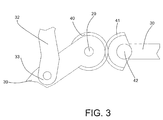
- Figure 3 shows an alternative embodiment of the manual movement means 5.
- the portion of the third rocker arm 28 forming the first end 31 is substituted by a first ring gear 40 concentric to the third pin 29.
- the first ring gear meshes with a second ring gear 41 pivoted at the main body 2 by means of a fourth pin 42.
- the second ring gear 41 may be rotatably driven about the fourth pin 42 by an actuator element 30 which may be rigidly connected either directly to the second ring gear 41 or to a through-bar (not illustrated) which joins two ring gears 41 positioned on the two sides of the main body 2 (similarly to what is described above relative to the third rocker arms 28).
- the actuator element 30 is not rigidly constrained to the third rocker arm 28 but only engages with it.
- the manual movement means 5 comprise an engagement element 39 integral with the third rocker arm 28 (with only one of the two in the accompanying drawings).
- the engagement element 39 is positioned in such a way that it causes, by rotation of the first and second rocker arms 17, 22, movement of the pusher element 11 from the home position to the operating position after the main body 2 has moved from the closed position to the open position, as well as rotation of the second rocker arm 22 from its first position to its second position after the main body 2 has moved from the closed position to the open position.
- the housing 3 is positioned at an angle to the horizontal, so that the movement of the pusher element 11 to the operating position causes the capsule to come out of the housing 3 due to the effect of gravity.
- Operation of the apparatus 1 disclosed is the same as that of prior art apparatuses as regards loading the capsule and preparing the drink.
- the operator can easily remove the used capsule, or if the housing 3 is at a sufficient angle, it may drop out of the housing 3 on its own.
- the present invention brings important advantages.
Landscapes
- Engineering & Computer Science (AREA)
- Food Science & Technology (AREA)
- Apparatus For Making Beverages (AREA)
Priority Applications (1)
| Application Number | Priority Date | Filing Date | Title |
|---|---|---|---|
| EP07109590A EP2000064A1 (de) | 2007-06-05 | 2007-06-05 | Vorrichtung zur Getränkeherstellung |
Applications Claiming Priority (1)
| Application Number | Priority Date | Filing Date | Title |
|---|---|---|---|
| EP07109590A EP2000064A1 (de) | 2007-06-05 | 2007-06-05 | Vorrichtung zur Getränkeherstellung |
Publications (1)
| Publication Number | Publication Date |
|---|---|
| EP2000064A1 true EP2000064A1 (de) | 2008-12-10 |
Family
ID=38707261
Family Applications (1)
| Application Number | Title | Priority Date | Filing Date |
|---|---|---|---|
| EP07109590A Withdrawn EP2000064A1 (de) | 2007-06-05 | 2007-06-05 | Vorrichtung zur Getränkeherstellung |
Country Status (1)
| Country | Link |
|---|---|
| EP (1) | EP2000064A1 (de) |
Cited By (1)
| Publication number | Priority date | Publication date | Assignee | Title |
|---|---|---|---|---|
| EP3558072A4 (de) * | 2016-12-22 | 2020-06-03 | Pepsico, Inc. | Getränkespendersystem und -verfahren |
Citations (2)
| Publication number | Priority date | Publication date | Assignee | Title |
|---|---|---|---|---|
| EP0151252A1 (de) * | 1984-01-26 | 1985-08-14 | Societe Des Produits Nestle S.A. | Kaffeemaschine |
| WO2007045553A1 (en) * | 2005-10-19 | 2007-04-26 | Ariete S.P.A. | Device for expelling used prepackaged capsules for espresso coffee machines |
-
2007
- 2007-06-05 EP EP07109590A patent/EP2000064A1/de not_active Withdrawn
Patent Citations (2)
| Publication number | Priority date | Publication date | Assignee | Title |
|---|---|---|---|---|
| EP0151252A1 (de) * | 1984-01-26 | 1985-08-14 | Societe Des Produits Nestle S.A. | Kaffeemaschine |
| WO2007045553A1 (en) * | 2005-10-19 | 2007-04-26 | Ariete S.P.A. | Device for expelling used prepackaged capsules for espresso coffee machines |
Cited By (2)
| Publication number | Priority date | Publication date | Assignee | Title |
|---|---|---|---|---|
| EP3558072A4 (de) * | 2016-12-22 | 2020-06-03 | Pepsico, Inc. | Getränkespendersystem und -verfahren |
| AU2017382522B2 (en) * | 2016-12-22 | 2023-11-23 | Pepsico, Inc. | Beverage dispenser systems and methods |
Similar Documents
| Publication | Publication Date | Title |
|---|---|---|
| EP1559351B1 (de) | Brühvorrichtung für eine Kaffeemaschine | |
| JP5451650B2 (ja) | 飲料を準備するための装置およびカプセル | |
| EP2000063B1 (de) | Verfahren zur Herstellung eines Getränks sowie Vorrichtung und Kapsel zur Anwendung dieses Verfahrens | |
| JP5492093B2 (ja) | 一回使い切りパッケージから飲料を用意するための抽出用ユニット及びそのユニットを含む装置 | |
| CN101484051B (zh) | 胶囊穿刺模块 | |
| EP1767129B2 (de) | Extraktionsmodul für eine auf Kapseln basierte Getränkemaschine | |
| RU2560865C2 (ru) | Заварочное устройство для экстрагирования порционной капсулы, способ эксплуатации заварочного устройства, и применение заварочного устройства | |
| JP5600738B2 (ja) | 一回使用分小袋から飲料を作るための注入ユニットおよびそのユニットを有する装置 | |
| EP2571405B1 (de) | Getränkeherstellungssystem mit kapseln | |
| TW200911184A (en) | System and method for preparing a liquid beverage from a cartridge | |
| US20100206177A1 (en) | Assembly comprising an appliance and a disposable capsule for producing a brewed drink, and capsule for such an assembly | |
| DE202006002678U1 (de) | Kaffeemaschine zur Zubereitung eines Kaffeegetränks mittels abgepackter, vorportionierter Kaffeepouches | |
| KR102188803B1 (ko) | 분말 식품 재료가 담긴 캡슐을 이용하여 음료를 만들기 위한 수평 유닛 및 음료를 제조하기 위한 기계 | |
| PT2131704E (pt) | Dispositivo para preparar uma bebida líquida a partir de uma cápsula | |
| EP3187077B1 (de) | Vorrichtung zur zubereitung eines getränks aus einer kapsel mit einem schliesssystem mit zwei schliessstufen | |
| PT756843E (pt) | Maquina para preparar bebidas tais como cafe expresso com introducao automatica do cafe moido e expulsao automatica das borras | |
| EP1842467A2 (de) | Vorrichtung und Verfahren zur portionsweisen Herstellung eines Aromagetränks | |
| WO2014174462A1 (en) | Machine for dispensing beverages | |
| JP2013538609A (ja) | カプセルを認識する調合装置 | |
| EP2000064A1 (de) | Vorrichtung zur Getränkeherstellung | |
| EP2606779B1 (de) | Infusionseinheit | |
| EP3358998B1 (de) | Kaffeemaschine zur verwendung mit kapseln | |
| IT202100012077A1 (it) | Apparecchiatura per la preparazione di una bevanda tramite infusione di una sostanza alimentare contenuta in una capsula | |
| HK1058296A (en) | Automatic device for the extraction of substances | |
| HK1127984B (en) | Capsule piercing module |
Legal Events
| Date | Code | Title | Description |
|---|---|---|---|
| PUAI | Public reference made under article 153(3) epc to a published international application that has entered the european phase |
Free format text: ORIGINAL CODE: 0009012 |
|
| AK | Designated contracting states |
Kind code of ref document: A1 Designated state(s): AT BE BG CH CY CZ DE DK EE ES FI FR GB GR HU IE IS IT LI LT LU LV MC MT NL PL PT RO SE SI SK TR |
|
| AX | Request for extension of the european patent |
Extension state: AL BA HR MK RS |
|
| AKX | Designation fees paid | ||
| REG | Reference to a national code |
Ref country code: DE Ref legal event code: 8566 |
|
| STAA | Information on the status of an ep patent application or granted ep patent |
Free format text: STATUS: THE APPLICATION IS DEEMED TO BE WITHDRAWN |
|
| 18D | Application deemed to be withdrawn |
Effective date: 20090611 |