EP2000344A2 - Structure pour monter une machine electrique et vehicule electrique - Google Patents
Structure pour monter une machine electrique et vehicule electrique Download PDFInfo
- Publication number
- EP2000344A2 EP2000344A2 EP07708429A EP07708429A EP2000344A2 EP 2000344 A2 EP2000344 A2 EP 2000344A2 EP 07708429 A EP07708429 A EP 07708429A EP 07708429 A EP07708429 A EP 07708429A EP 2000344 A2 EP2000344 A2 EP 2000344A2
- Authority
- EP
- European Patent Office
- Prior art keywords
- electric equipment
- mounting structure
- pcu
- vehicle
- structure according
- Prior art date
- Legal status (The legal status is an assumption and is not a legal conclusion. Google has not performed a legal analysis and makes no representation as to the accuracy of the status listed.)
- Granted
Links
Images


Classifications
-
- B—PERFORMING OPERATIONS; TRANSPORTING
- B60—VEHICLES IN GENERAL
- B60K—ARRANGEMENT OR MOUNTING OF PROPULSION UNITS OR OF TRANSMISSIONS IN VEHICLES; ARRANGEMENT OR MOUNTING OF PLURAL DIVERSE PRIME-MOVERS IN VEHICLES; AUXILIARY DRIVES FOR VEHICLES; INSTRUMENTATION OR DASHBOARDS FOR VEHICLES; ARRANGEMENTS IN CONNECTION WITH COOLING, AIR INTAKE, GAS EXHAUST OR FUEL SUPPLY OF PROPULSION UNITS IN VEHICLES
- B60K6/00—Arrangement or mounting of plural diverse prime-movers for mutual or common propulsion, e.g. hybrid propulsion systems comprising electric motors and internal combustion engines
- B60K6/20—Arrangement or mounting of plural diverse prime-movers for mutual or common propulsion, e.g. hybrid propulsion systems comprising electric motors and internal combustion engines the prime-movers consisting of electric motors and internal combustion engines, e.g. HEVs
- B60K6/22—Arrangement or mounting of plural diverse prime-movers for mutual or common propulsion, e.g. hybrid propulsion systems comprising electric motors and internal combustion engines the prime-movers consisting of electric motors and internal combustion engines, e.g. HEVs characterised by apparatus, components or means specially adapted for HEVs
- B60K6/40—Arrangement or mounting of plural diverse prime-movers for mutual or common propulsion, e.g. hybrid propulsion systems comprising electric motors and internal combustion engines the prime-movers consisting of electric motors and internal combustion engines, e.g. HEVs characterised by apparatus, components or means specially adapted for HEVs characterised by the assembly or relative disposition of components
-
- B—PERFORMING OPERATIONS; TRANSPORTING
- B60—VEHICLES IN GENERAL
- B60K—ARRANGEMENT OR MOUNTING OF PROPULSION UNITS OR OF TRANSMISSIONS IN VEHICLES; ARRANGEMENT OR MOUNTING OF PLURAL DIVERSE PRIME-MOVERS IN VEHICLES; AUXILIARY DRIVES FOR VEHICLES; INSTRUMENTATION OR DASHBOARDS FOR VEHICLES; ARRANGEMENTS IN CONNECTION WITH COOLING, AIR INTAKE, GAS EXHAUST OR FUEL SUPPLY OF PROPULSION UNITS IN VEHICLES
- B60K1/00—Arrangement or mounting of electrical propulsion units
-
- B—PERFORMING OPERATIONS; TRANSPORTING
- B60—VEHICLES IN GENERAL
- B60K—ARRANGEMENT OR MOUNTING OF PROPULSION UNITS OR OF TRANSMISSIONS IN VEHICLES; ARRANGEMENT OR MOUNTING OF PLURAL DIVERSE PRIME-MOVERS IN VEHICLES; AUXILIARY DRIVES FOR VEHICLES; INSTRUMENTATION OR DASHBOARDS FOR VEHICLES; ARRANGEMENTS IN CONNECTION WITH COOLING, AIR INTAKE, GAS EXHAUST OR FUEL SUPPLY OF PROPULSION UNITS IN VEHICLES
- B60K13/00—Arrangement in connection with combustion air intake or gas exhaust of propulsion units
- B60K13/02—Arrangement in connection with combustion air intake or gas exhaust of propulsion units concerning intake
-
- B—PERFORMING OPERATIONS; TRANSPORTING
- B60—VEHICLES IN GENERAL
- B60K—ARRANGEMENT OR MOUNTING OF PROPULSION UNITS OR OF TRANSMISSIONS IN VEHICLES; ARRANGEMENT OR MOUNTING OF PLURAL DIVERSE PRIME-MOVERS IN VEHICLES; AUXILIARY DRIVES FOR VEHICLES; INSTRUMENTATION OR DASHBOARDS FOR VEHICLES; ARRANGEMENTS IN CONNECTION WITH COOLING, AIR INTAKE, GAS EXHAUST OR FUEL SUPPLY OF PROPULSION UNITS IN VEHICLES
- B60K6/00—Arrangement or mounting of plural diverse prime-movers for mutual or common propulsion, e.g. hybrid propulsion systems comprising electric motors and internal combustion engines
- B60K6/20—Arrangement or mounting of plural diverse prime-movers for mutual or common propulsion, e.g. hybrid propulsion systems comprising electric motors and internal combustion engines the prime-movers consisting of electric motors and internal combustion engines, e.g. HEVs
- B60K6/22—Arrangement or mounting of plural diverse prime-movers for mutual or common propulsion, e.g. hybrid propulsion systems comprising electric motors and internal combustion engines the prime-movers consisting of electric motors and internal combustion engines, e.g. HEVs characterised by apparatus, components or means specially adapted for HEVs
- B60K6/36—Arrangement or mounting of plural diverse prime-movers for mutual or common propulsion, e.g. hybrid propulsion systems comprising electric motors and internal combustion engines the prime-movers consisting of electric motors and internal combustion engines, e.g. HEVs characterised by apparatus, components or means specially adapted for HEVs characterised by the transmission gearings
- B60K6/365—Arrangement or mounting of plural diverse prime-movers for mutual or common propulsion, e.g. hybrid propulsion systems comprising electric motors and internal combustion engines the prime-movers consisting of electric motors and internal combustion engines, e.g. HEVs characterised by apparatus, components or means specially adapted for HEVs characterised by the transmission gearings with the gears having orbital motion
-
- B—PERFORMING OPERATIONS; TRANSPORTING
- B60—VEHICLES IN GENERAL
- B60K—ARRANGEMENT OR MOUNTING OF PROPULSION UNITS OR OF TRANSMISSIONS IN VEHICLES; ARRANGEMENT OR MOUNTING OF PLURAL DIVERSE PRIME-MOVERS IN VEHICLES; AUXILIARY DRIVES FOR VEHICLES; INSTRUMENTATION OR DASHBOARDS FOR VEHICLES; ARRANGEMENTS IN CONNECTION WITH COOLING, AIR INTAKE, GAS EXHAUST OR FUEL SUPPLY OF PROPULSION UNITS IN VEHICLES
- B60K6/00—Arrangement or mounting of plural diverse prime-movers for mutual or common propulsion, e.g. hybrid propulsion systems comprising electric motors and internal combustion engines
- B60K6/20—Arrangement or mounting of plural diverse prime-movers for mutual or common propulsion, e.g. hybrid propulsion systems comprising electric motors and internal combustion engines the prime-movers consisting of electric motors and internal combustion engines, e.g. HEVs
- B60K6/42—Arrangement or mounting of plural diverse prime-movers for mutual or common propulsion, e.g. hybrid propulsion systems comprising electric motors and internal combustion engines the prime-movers consisting of electric motors and internal combustion engines, e.g. HEVs characterised by the architecture of the hybrid electric vehicle
- B60K6/44—Series-parallel type
- B60K6/445—Differential gearing distribution type
-
- B—PERFORMING OPERATIONS; TRANSPORTING
- B60—VEHICLES IN GENERAL
- B60L—PROPULSION OF ELECTRICALLY-PROPELLED VEHICLES; SUPPLYING ELECTRIC POWER FOR AUXILIARY EQUIPMENT OF ELECTRICALLY-PROPELLED VEHICLES; ELECTRODYNAMIC BRAKE SYSTEMS FOR VEHICLES IN GENERAL; MAGNETIC SUSPENSION OR LEVITATION FOR VEHICLES; MONITORING OPERATING VARIABLES OF ELECTRICALLY-PROPELLED VEHICLES; ELECTRIC SAFETY DEVICES FOR ELECTRICALLY-PROPELLED VEHICLES
- B60L3/00—Electric devices on electrically-propelled vehicles for safety purposes; Monitoring operating variables, e.g. speed, deceleration or energy consumption
- B60L3/0007—Measures or means for preventing or attenuating collisions
-
- B—PERFORMING OPERATIONS; TRANSPORTING
- B60—VEHICLES IN GENERAL
- B60L—PROPULSION OF ELECTRICALLY-PROPELLED VEHICLES; SUPPLYING ELECTRIC POWER FOR AUXILIARY EQUIPMENT OF ELECTRICALLY-PROPELLED VEHICLES; ELECTRODYNAMIC BRAKE SYSTEMS FOR VEHICLES IN GENERAL; MAGNETIC SUSPENSION OR LEVITATION FOR VEHICLES; MONITORING OPERATING VARIABLES OF ELECTRICALLY-PROPELLED VEHICLES; ELECTRIC SAFETY DEVICES FOR ELECTRICALLY-PROPELLED VEHICLES
- B60L3/00—Electric devices on electrically-propelled vehicles for safety purposes; Monitoring operating variables, e.g. speed, deceleration or energy consumption
- B60L3/0023—Detecting, eliminating, remedying or compensating for drive train abnormalities, e.g. failures within the drive train
- B60L3/0069—Detecting, eliminating, remedying or compensating for drive train abnormalities, e.g. failures within the drive train relating to the isolation, e.g. ground fault or leak current
-
- B—PERFORMING OPERATIONS; TRANSPORTING
- B60—VEHICLES IN GENERAL
- B60L—PROPULSION OF ELECTRICALLY-PROPELLED VEHICLES; SUPPLYING ELECTRIC POWER FOR AUXILIARY EQUIPMENT OF ELECTRICALLY-PROPELLED VEHICLES; ELECTRODYNAMIC BRAKE SYSTEMS FOR VEHICLES IN GENERAL; MAGNETIC SUSPENSION OR LEVITATION FOR VEHICLES; MONITORING OPERATING VARIABLES OF ELECTRICALLY-PROPELLED VEHICLES; ELECTRIC SAFETY DEVICES FOR ELECTRICALLY-PROPELLED VEHICLES
- B60L50/00—Electric propulsion with power supplied within the vehicle
- B60L50/10—Electric propulsion with power supplied within the vehicle using propulsion power supplied by engine-driven generators, e.g. generators driven by combustion engines
- B60L50/16—Electric propulsion with power supplied within the vehicle using propulsion power supplied by engine-driven generators, e.g. generators driven by combustion engines with provision for separate direct mechanical propulsion
-
- B—PERFORMING OPERATIONS; TRANSPORTING
- B60—VEHICLES IN GENERAL
- B60L—PROPULSION OF ELECTRICALLY-PROPELLED VEHICLES; SUPPLYING ELECTRIC POWER FOR AUXILIARY EQUIPMENT OF ELECTRICALLY-PROPELLED VEHICLES; ELECTRODYNAMIC BRAKE SYSTEMS FOR VEHICLES IN GENERAL; MAGNETIC SUSPENSION OR LEVITATION FOR VEHICLES; MONITORING OPERATING VARIABLES OF ELECTRICALLY-PROPELLED VEHICLES; ELECTRIC SAFETY DEVICES FOR ELECTRICALLY-PROPELLED VEHICLES
- B60L50/00—Electric propulsion with power supplied within the vehicle
- B60L50/50—Electric propulsion with power supplied within the vehicle using propulsion power supplied by batteries or fuel cells
- B60L50/60—Electric propulsion with power supplied within the vehicle using propulsion power supplied by batteries or fuel cells using power supplied by batteries
- B60L50/61—Electric propulsion with power supplied within the vehicle using propulsion power supplied by batteries or fuel cells using power supplied by batteries by batteries charged by engine-driven generators, e.g. series hybrid electric vehicles
-
- B—PERFORMING OPERATIONS; TRANSPORTING
- B60—VEHICLES IN GENERAL
- B60L—PROPULSION OF ELECTRICALLY-PROPELLED VEHICLES; SUPPLYING ELECTRIC POWER FOR AUXILIARY EQUIPMENT OF ELECTRICALLY-PROPELLED VEHICLES; ELECTRODYNAMIC BRAKE SYSTEMS FOR VEHICLES IN GENERAL; MAGNETIC SUSPENSION OR LEVITATION FOR VEHICLES; MONITORING OPERATING VARIABLES OF ELECTRICALLY-PROPELLED VEHICLES; ELECTRIC SAFETY DEVICES FOR ELECTRICALLY-PROPELLED VEHICLES
- B60L50/00—Electric propulsion with power supplied within the vehicle
- B60L50/50—Electric propulsion with power supplied within the vehicle using propulsion power supplied by batteries or fuel cells
- B60L50/60—Electric propulsion with power supplied within the vehicle using propulsion power supplied by batteries or fuel cells using power supplied by batteries
- B60L50/66—Arrangements of batteries
-
- B—PERFORMING OPERATIONS; TRANSPORTING
- B60—VEHICLES IN GENERAL
- B60W—CONJOINT CONTROL OF VEHICLE SUB-UNITS OF DIFFERENT TYPE OR DIFFERENT FUNCTION; CONTROL SYSTEMS SPECIALLY ADAPTED FOR HYBRID VEHICLES; ROAD VEHICLE DRIVE CONTROL SYSTEMS FOR PURPOSES NOT RELATED TO THE CONTROL OF A PARTICULAR SUB-UNIT
- B60W10/00—Conjoint control of vehicle sub-units of different type or different function
- B60W10/04—Conjoint control of vehicle sub-units of different type or different function including control of propulsion units
- B60W10/08—Conjoint control of vehicle sub-units of different type or different function including control of propulsion units including control of electric propulsion units, e.g. motors or generators
-
- B—PERFORMING OPERATIONS; TRANSPORTING
- B60—VEHICLES IN GENERAL
- B60L—PROPULSION OF ELECTRICALLY-PROPELLED VEHICLES; SUPPLYING ELECTRIC POWER FOR AUXILIARY EQUIPMENT OF ELECTRICALLY-PROPELLED VEHICLES; ELECTRODYNAMIC BRAKE SYSTEMS FOR VEHICLES IN GENERAL; MAGNETIC SUSPENSION OR LEVITATION FOR VEHICLES; MONITORING OPERATING VARIABLES OF ELECTRICALLY-PROPELLED VEHICLES; ELECTRIC SAFETY DEVICES FOR ELECTRICALLY-PROPELLED VEHICLES
- B60L2220/00—Electrical machine types; Structures or applications thereof
- B60L2220/10—Electrical machine types
- B60L2220/14—Synchronous machines
-
- B—PERFORMING OPERATIONS; TRANSPORTING
- B60—VEHICLES IN GENERAL
- B60L—PROPULSION OF ELECTRICALLY-PROPELLED VEHICLES; SUPPLYING ELECTRIC POWER FOR AUXILIARY EQUIPMENT OF ELECTRICALLY-PROPELLED VEHICLES; ELECTRODYNAMIC BRAKE SYSTEMS FOR VEHICLES IN GENERAL; MAGNETIC SUSPENSION OR LEVITATION FOR VEHICLES; MONITORING OPERATING VARIABLES OF ELECTRICALLY-PROPELLED VEHICLES; ELECTRIC SAFETY DEVICES FOR ELECTRICALLY-PROPELLED VEHICLES
- B60L2240/00—Control parameters of input or output; Target parameters
- B60L2240/40—Drive Train control parameters
- B60L2240/42—Drive Train control parameters related to electric machines
- B60L2240/421—Speed
-
- B—PERFORMING OPERATIONS; TRANSPORTING
- B60—VEHICLES IN GENERAL
- B60W—CONJOINT CONTROL OF VEHICLE SUB-UNITS OF DIFFERENT TYPE OR DIFFERENT FUNCTION; CONTROL SYSTEMS SPECIALLY ADAPTED FOR HYBRID VEHICLES; ROAD VEHICLE DRIVE CONTROL SYSTEMS FOR PURPOSES NOT RELATED TO THE CONTROL OF A PARTICULAR SUB-UNIT
- B60W20/00—Control systems specially adapted for hybrid vehicles
-
- B—PERFORMING OPERATIONS; TRANSPORTING
- B60—VEHICLES IN GENERAL
- B60W—CONJOINT CONTROL OF VEHICLE SUB-UNITS OF DIFFERENT TYPE OR DIFFERENT FUNCTION; CONTROL SYSTEMS SPECIALLY ADAPTED FOR HYBRID VEHICLES; ROAD VEHICLE DRIVE CONTROL SYSTEMS FOR PURPOSES NOT RELATED TO THE CONTROL OF A PARTICULAR SUB-UNIT
- B60W2510/00—Input parameters relating to a particular sub-units
- B60W2510/08—Electric propulsion units
- B60W2510/081—Speed
-
- Y—GENERAL TAGGING OF NEW TECHNOLOGICAL DEVELOPMENTS; GENERAL TAGGING OF CROSS-SECTIONAL TECHNOLOGIES SPANNING OVER SEVERAL SECTIONS OF THE IPC; TECHNICAL SUBJECTS COVERED BY FORMER USPC CROSS-REFERENCE ART COLLECTIONS [XRACs] AND DIGESTS
- Y02—TECHNOLOGIES OR APPLICATIONS FOR MITIGATION OR ADAPTATION AGAINST CLIMATE CHANGE
- Y02T—CLIMATE CHANGE MITIGATION TECHNOLOGIES RELATED TO TRANSPORTATION
- Y02T10/00—Road transport of goods or passengers
- Y02T10/60—Other road transportation technologies with climate change mitigation effect
- Y02T10/62—Hybrid vehicles
-
- Y—GENERAL TAGGING OF NEW TECHNOLOGICAL DEVELOPMENTS; GENERAL TAGGING OF CROSS-SECTIONAL TECHNOLOGIES SPANNING OVER SEVERAL SECTIONS OF THE IPC; TECHNICAL SUBJECTS COVERED BY FORMER USPC CROSS-REFERENCE ART COLLECTIONS [XRACs] AND DIGESTS
- Y02—TECHNOLOGIES OR APPLICATIONS FOR MITIGATION OR ADAPTATION AGAINST CLIMATE CHANGE
- Y02T—CLIMATE CHANGE MITIGATION TECHNOLOGIES RELATED TO TRANSPORTATION
- Y02T10/00—Road transport of goods or passengers
- Y02T10/60—Other road transportation technologies with climate change mitigation effect
- Y02T10/64—Electric machine technologies in electromobility
-
- Y—GENERAL TAGGING OF NEW TECHNOLOGICAL DEVELOPMENTS; GENERAL TAGGING OF CROSS-SECTIONAL TECHNOLOGIES SPANNING OVER SEVERAL SECTIONS OF THE IPC; TECHNICAL SUBJECTS COVERED BY FORMER USPC CROSS-REFERENCE ART COLLECTIONS [XRACs] AND DIGESTS
- Y02—TECHNOLOGIES OR APPLICATIONS FOR MITIGATION OR ADAPTATION AGAINST CLIMATE CHANGE
- Y02T—CLIMATE CHANGE MITIGATION TECHNOLOGIES RELATED TO TRANSPORTATION
- Y02T10/00—Road transport of goods or passengers
- Y02T10/60—Other road transportation technologies with climate change mitigation effect
- Y02T10/70—Energy storage systems for electromobility, e.g. batteries
-
- Y—GENERAL TAGGING OF NEW TECHNOLOGICAL DEVELOPMENTS; GENERAL TAGGING OF CROSS-SECTIONAL TECHNOLOGIES SPANNING OVER SEVERAL SECTIONS OF THE IPC; TECHNICAL SUBJECTS COVERED BY FORMER USPC CROSS-REFERENCE ART COLLECTIONS [XRACs] AND DIGESTS
- Y02—TECHNOLOGIES OR APPLICATIONS FOR MITIGATION OR ADAPTATION AGAINST CLIMATE CHANGE
- Y02T—CLIMATE CHANGE MITIGATION TECHNOLOGIES RELATED TO TRANSPORTATION
- Y02T10/00—Road transport of goods or passengers
- Y02T10/60—Other road transportation technologies with climate change mitigation effect
- Y02T10/7072—Electromobility specific charging systems or methods for batteries, ultracapacitors, supercapacitors or double-layer capacitors
Definitions
- the present invention relates to an electric equipment mounting structure and to an electric vehicle.
- the present invention relates to an electric equipment mounting structure mounted inside a closed space in a vehicle, and to an electric vehicle with such a structure.
- Patent Document 1 discloses an engine intake device of a hybrid vehicle provided with an inverter inside a housing of an air cleaner.
- Patent Document 2 discloses a power control unit, wherein a reinforcing member is provided on an outer wall of a high-voltage box, and a high-voltage terminal block is provided on an inner wall of the high-voltage box protected by the reinforcing member.
- Patent Document 3 discloses a vehicle body structure provided with a displacement allowance space for allowing for displacement of a unit box upon collision.
- Patent Document 4 discloses a structure including a bracket that deforms following deformation of a vehicle frame member and an inverter fixed to the vehicle frame member with the bracket.
- an inverter also displaces following displacement of the bracket, so as to prevent a high-voltage line connected to the inverter from being caught between the vehicle frame member and the inverter.
- Patent Document 1 the inverter is provided inside the housing of the air cleaner. This complicates the structure of the air cleaner and increases costs. Patent Documents 2-4 also fail to disclose any configuration that can sufficiently protect the high-voltage cable while suppressing an increase in costs.
- An object of the present invention is to provide an electric equipment mounting structure being capable of protecting a line while suppressing an increase in costs, and to provide an electric vehicle with such a structure.
- An electric equipment mounting structure includes: electric equipment mounted inside a closed space of a vehicle; a resin component mounted inside the closed space of the vehicle with a distance from the electric equipment; and a line connected to a surface facing the resin component, of the electric equipment.
- a "resin component” refers to a component that includes a resin portion that deforms easier than the electric equipment when receiving a load.
- a plurality of the lines are connected to the surface, facing the resin component, of the electric equipment.
- the line is connected to a surface, positioned on a rear side of the vehicle, of the electric equipment.
- the line can be protected from a load from the front side of the vehicle.
- the electric equipment and the resin component are provided so as to align in a lateral direction.
- the line can be protected from a load from the lateral direction.
- the electric equipment mounting structure further includes an other line connected to a surface of the electric equipment, the surface being different from the surface facing the resin component.
- the line connected to the surface, facing the resin component, of the electric equipment is higher in voltage than the other line.
- the line of high voltage can be protected on a priority basis.
- the electric equipment is for a voltage not lower than 42V.
- lines for a voltage not lower than 42V connected to the electric equipment are all connected to the surface, facing the resin component, of the electric equipment.
- the electric equipment includes an inverter.
- the closed space is an engine room where an internal combustion engine is provided
- the resin component includes a case of an air cleaner provided in an air intake route of the internal combustion engine.
- the air cleaner includes the case being a component made of resin and a filter stored in the case, and deforms easier than the electric equipment when receiving a load.
- the air cleaner is provided on a rear side of the vehicle relative to the electric equipment, and the line is connected to a side surface, positioned on the rear side of the vehicle, of the electric equipment.
- the electric equipment mounting structure further includes a motor-generator driving the vehicle.
- the electric equipment controls an operation of the motor-generator.
- An electric vehicle according to the present invention includes the above-described electric equipment mounting structure.
- an electric vehicle incorporating an electric equipment mounting structure being capable of protecting a line while suppressing an increase in costs can be obtained.
- an "electric vehicle” includes all of a hybrid vehicle, a fuel-cell vehicle, and an electric vehicle.
- an electric equipment mounting structure being capable of protecting a line while suppressing an increase in costs can be obtained.
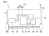
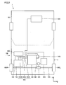
- Figs. 1 and 2 are schematic views showing a configuration of a hybrid vehicle having an electric equipment mounting structure according to one embodiment of the present invention.
- Fig. 2 shows a state as seen from the direction of arrow II in Fig. 1 .
- a hybrid vehicle 1 includes an engine 100, a motor-generator 200, a power split device 300, a differential mechanism 400, a driveshaft 500, driving wheels 600L, 600R being the front wheels, a PCU (Power Control Unit) 700, an air cleaner 800, a battery 1000, and A/C (air conditioner) compressor 1100.
- a PCU Power Control Unit
- A/C air conditioner
- engine 100, motor-generator 200, power split device 300, PCU 700, and an A/C compressor 1100 are arranged inside engine room 2.
- Motor-generator 200 and PCU 700 are connected by a cable 900A.
- PCU 700 and battery 1000 are connected by a cable 900B.
- PCU 700 and A/C compressor 1100 are connected by a cable 900C.
- a power output apparatus formed by engine 100 and motor-generator 200 is coupled to differential mechanism 400 through power split device 300.
- Differential mechanism 400 is coupled to driving wheels 600L, 600R via driveshaft 500.
- Motor-generator 200 is a three-phase AC (alternating current) synchronous motor-generator that generates drive force by AC power received from PCU 700. Motor-generator 200 is also used as a generator upon deceleration or the like of hybrid vehicle 1. By the generation function (regeneration), motor-generator 200 generates AC power which is output to PCU 700.
- PCU 700 converts a DC (direct current) voltage received from battery 1000 into an AC voltage and exerts control to drive motor-generator 200. PCU 700 also converts an AC voltage generated by motor-generator 200 into a DC voltage and charges battery 1000.
- DC direct current
- Power split device 300 is configured to include a planetary gear (not shown), for example.
- the motive power output from engine 100 and/or motor-generator 200 is transmitted from power split device 300 through differential mechanism 400 to driveshaft 500.
- the drive power transmitted to driveshaft 500 is transmitted to driving wheels 600L, 600R as rotation power, thereby allowing the vehicle to travel.
- motor-generator 200 functions as a motor.
- motor-generator 200 is driven by driving wheels 600L, 600R or engine 100.
- motor-generator 200 functions as a generator.
- the power generated by motor-generator 200 is stored in battery 1000 through an inverter inside PCU 700.
- Fig. 3 is a circuit diagram showing a configuration of a substantial part of PCU 700.
- PCU 700 includes a converter 710, an inverter 720, a control apparatus 730, capacitors C1, C2, power supply lines PL1-PL3, and output lines 740U, 740V, 740W.
- Converter 710 is connected between battery 1000 and inverter 720.
- Inverter 720 is connected to motor-generator 200 through output lines 740U, 740V, 740W.
- Battery 1000 connected to converter 710 is a rechargeable battery such as a nickel-hydride or lithium ion battery. Battery 1000 supplies the generated DC voltage to converter 710, and is charged by the DC voltage received from converter 710.
- Converter 710 is formed by power transistors Q1, Q2, diodes D1, D2, and a reactor L.
- Power transistors Q1, Q2 are connected in series between power supply lines PL2, PL3, and each receive at the base a control signal from control apparatus 730.
- Diodes D1, D2 are connected across collector and emitter of power transistors Q1, Q2, respectively, so as to pass currents from emitter side to collector side of power transistors Q1, Q2.
- Reactor L has one end connected to power supply line PL1 that is connected to the positive electrode of battery 1000, and has the other end connected to a connection point of power transistors Q1 and Q2.
- Converter 710 uses reactor L to boost a DC voltage received from battery 1000, and supplies the boosted boost voltage to power supply line PL2. Also, converter 710 steps down a DC voltage received from inverter 720 and charges battery 1000.
- Inverter 720 is formed by a U-phase arm 750U, a V-phase arm 750V and a W-phase arm 750W. These phase arms are connected in parallel between power supply lines PL2 and PL3.
- U-phase arm 750U includes power transistors Q3, Q4 connected in series.
- V-phase arm 750V includes power transistors Q5, Q6 connected in series.
- W-phase arm 750W includes power transistors Q7, Q8 connected in series.
- Diodes D3-D8 are connected across collector and emitter of power transistors Q3-Q8, respectively, so as to pass currents from emitter side to collector side of power transistors Q3-Q8.
- the power transistors have their connection point connected through output line 740U, 740V, or 740W to a node of each phase coil of motor-generator 200 being opposite to the neutral point.
- inverter 720 Based on a control signal from control apparatus 730, inverter 720 converts a DC voltage received from power supply line PL2 into an AC voltage and outputs the same to motor-generator 200. Inverter 720 rectifies an AC voltage generated by motor-generator 200 into a DC voltage and supplies the same to power supply line PL2.
- Capacitor C1 is connected between power supply lines PL1 and PL3, and smoothes the voltage level of power supply line PL1.
- Capacitor C2 is connected between power supply lines PL2 and PL3 and smoothes the voltage level of power supply line PL2.
- Control apparatus 730 calculates each phase coil voltage of motor-generator 200 based on a motor torque command value, each phase current value of motor-generator 200, and an input voltage of inverter 720. Based on the calculation result, control apparatus 730 generates a PWM (Pulse Width Modulation) signal turning on/off power transistors Q3-Q8 and outputs the same to inverter 720.
- PWM Pulse Width Modulation
- Control apparatus 730 calculates a duty ratio of power transistors Q1, Q2 for optimizing the input voltage of inverter 720, based on the above-mentioned motor torque command value and a motor rotation speed. Based on the calculation result, control apparatus 730 generates a PWM signal turning on/off power transistors Q1, Q2 and outputs the same to converter 710.
- control apparatus 73 0 exerts control over the switching operation of power transistors Q1-Q8 in converter 710 and inverter 720, so as to convert AC power generated by motor-generator 200 into DC power and charge battery 1000.
- converter 710 boosts a DC voltage received from battery 1000 and supplies the same to power supply line PL2.
- Inverter 720 receives from power supply line PL2 a DC voltage smoothed by capacitor C2. Inverter 720 converts the received DC voltage into an AC voltage and outputs the same to motor-generator 200.
- Inverter 720 converts an AC voltage generated by regenerative operation of motor-generator 200 into a DC voltage, and outputs the same to power supply line PL2. Then, converter 710 receives from power supply line PL2 a DC voltage smoothed by capacitor C2. Converter 710 steps down the received DC voltage and charges battery 1000.
- Cables 900 (900A, 900B, 900C) shown in Figs. 1 and 2 are high-voltage lines used at relatively high voltage (for example, about not less than 200V and not more than 600V). Accordingly, it is important to protect cables 900 and to prevent leak from cables 900.
- the vehicle body may deform or PCU 700 may move, upon collision of the vehicle or the like, for example.
- Fig. 4 shows a mounting structure for PCU 700 according to a comparative example.
- the mounting structure for PCU 700 according to the comparative example includes a PCU 700 and an air cleaner 800 provided on the rear side of the vehicle relative to PCU 700.
- Air cleaner 800 is a component provided in an air intake route to engine 100. Air cleaner 800 is supplied with air from an air intake port 1200.
- connection portion 901 A (a connector), being an attaching portion to PCU 700, of cable 900A connecting PCU 700 and motor-generator 200, and a connection portion 901 B, being an attaching portion to PCU 700, of cable 900B connecting PCU 700 and battery 1000, are provided on a side surface, on the front side of the vehicle, of PCU 700.
- a connection portion 901C being an attaching portion to PCU 700, of cable 900C connecting PCU 700 and A/C compressor 1100, is provided on a side surface, on the right as one faces the direction from frontward to rearward of the vehicle, of PCU 700.
- cables 900 in particular, cables 900A and 900B connected to connection portions 901A and 901B
- connection portions 901 (901A, 901B, 901C) will be caught between vehicle body 1A and PCU 700. If an attempt is made to fully protect cables 900 addressing this situation, the size of protection portions provided around cables 900 will be increased, or the structure of such protection portions will be complicated. Thus, costs will be increased.
- Fig. 5 shows a mounting structure for PCU 700 according to one embodiment.
- the mounting structure for PCU 700 according to the embodiment includes, similarly to the above-described comparative example, PCU 700 and air cleaner 800 provided on the rear side of the vehicle relative to PCU 700.
- connection portion 901 A being an attaching portion to PCU 700, of cable 900A connecting PCU 700 and motor-generator 200
- a connection portion 901B being an attaching portion to PCU 700, of cable 900B connecting PCU 700 and battery 1000
- a connection portion 901C being an attaching portion to PCU 700, of cable 900C connecting PCU 700 and A/C compressor 1100
- cables 900 (900A, 900B, 900C) connected to connection portions 901 (901A, 901B, 901C) will be caught between PCU 700 and air cleaner 800.
- air cleaner 800 is a relatively soft component, damage to cables 900 can be prevented without providing a cable protection portion of a large size/complicated structure around cables 900, even when cables 900 are caught between PCU 700 and air cleaner 800.
- cables 900 can be protected while suppressing an increase in costs.
- connection portions 901 (901A, 90 1 B, 90 1 C) are provided on the side surface of PCU 700 facing air cleaner 800
- a single connection portion 901 or a plurality of connection portions 901 of arbitrary numbers may be provided on the side surface of PCU 700 facing air cleaner 800.
- all the three connection portions 901A, 901B, 901C are provided on the side surface of PCU 700 facing air cleaner 800
- part of three connection portions 901 A, 901 B, 901C may be provided on a side surface of PCU 700 other than the side surface facing air cleaner 800.
- the voltage of cables (lines) connected to connection portions 901 provided on the side surface of PCU 700 facing air cleaner 800 is higher than the voltage of the cable (the other line) connected to connection portion 901 provided on the other side surface of PCU 700.
- the high-voltage cables can be protected on a priority basis.
- PCU 700 and air cleaner 800 are arranged so as to align in the lateral direction (substantially horizontal direction)
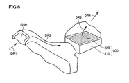
- FIG. 6 illustrates a structure of air cleaner 800.
- air cleaner 800 includes an air cleaner case 810 and a filter 820.
- the air flown into air intake port 1200 in the arrow DR1 direction flows along the arrow DR2 direction, and led to the inside of air cleaner case 810.
- the air reaching air cleaner case 810 passes through filter 820.
- the air having passed through filter 820 flows in the arrow DR3, DR4 directions and lead to the air intake portion of engine 100.
- air cleaner case 810 is a component made of resin.
- Filter 820 stored in air cleaner case 810 is a fine filter paper containing fibers.
- air cleaner 800 is configured to include a resin-made portion (air cleaner case 810), and it is a "resin component" that deforms easier than PCU 700 when receiving a load such as collision load.
- the electric equipment mounting structure includes: PCU 700 as "electric equipment” mounted inside engine room 2 (room for the internal combustion engine) as "a closed space” of hybrid vehicle 1; air cleaner 800 as "a resin component” mounted inside engine room 2 of hybrid vehicle 1 with a distance from PCU 700; and cables 900A, 900B, 900C as "lines” connected to the surface of PCU 700 facing air cleaner 800.
- engine room 2 of hybrid vehicle 1 constitutes "a closed space of the vehicle”
- PCU 700 including converter 710, inverter 720 and capacitors C1, C2 constitutes "electric equipment”
- air cleaner 800 provided in the air intake route of engine 100 constitutes "a resin component”.
- the space inside the engine room of a vehicle is limited, and often lines are positioned between PCU 700 and other components.
- connection portions 901A, 901B, 901C being "line drawing portions" of PCU 700 at the portion facing air cleaner 800, cable 900 can be protected.
- the "vehicle”, “closed space”, “electric equipment” and “resin component” are not limited to “hybrid vehicle 1", “engine room 2", “PCU 700", and “air cleaner 800", respectively.
- a unit other than PCU 700 that is of relatively high voltage (for example, about not less than 42V) and of which connection lines should desirably be protected may correspond to the "electric equipment”.
- equipment including at least one of a converter (for example, a DC-DC converter), an inverter and a capacitor or an actuator of high voltage can be used.
- a resin component protecting cables 900 is not limited to air cleaner 800, and an arbitrary component including a resin portion capable of protecting cables 900 with a simple structure may be applicable.
- engine 100 being "an internal combustion engine” may be a gasoline engine or a diesel engine.
- the present invention is applicable to an electric equipment mounting structure, an electric vehicle and the like, for example.
Landscapes
- Engineering & Computer Science (AREA)
- Transportation (AREA)
- Mechanical Engineering (AREA)
- Chemical & Material Sciences (AREA)
- Combustion & Propulsion (AREA)
- Power Engineering (AREA)
- Life Sciences & Earth Sciences (AREA)
- Sustainable Development (AREA)
- Sustainable Energy (AREA)
- Electric Propulsion And Braking For Vehicles (AREA)
- Arrangement Or Mounting Of Propulsion Units For Vehicles (AREA)
- Hybrid Electric Vehicles (AREA)
Applications Claiming Priority (2)
| Application Number | Priority Date | Filing Date | Title |
|---|---|---|---|
| JP2006046935A JP4305456B2 (ja) | 2006-02-23 | 2006-02-23 | 電気機器の搭載構造および電動車両 |
| PCT/JP2007/053464 WO2007105465A1 (fr) | 2006-02-23 | 2007-02-20 | Structure pour monter une machine electrique et vehicule electrique |
Publications (4)
| Publication Number | Publication Date |
|---|---|
| EP2000344A2 true EP2000344A2 (fr) | 2008-12-10 |
| EP2000344A9 EP2000344A9 (fr) | 2009-03-11 |
| EP2000344A4 EP2000344A4 (fr) | 2009-09-23 |
| EP2000344B1 EP2000344B1 (fr) | 2011-01-19 |
Family
ID=38509301
Family Applications (1)
| Application Number | Title | Priority Date | Filing Date |
|---|---|---|---|
| EP07708429A Active EP2000344B1 (fr) | 2006-02-23 | 2007-02-20 | Structure pour monter une machine electrique et vehicule electrique |
Country Status (6)
| Country | Link |
|---|---|
| US (1) | US7948112B2 (fr) |
| EP (1) | EP2000344B1 (fr) |
| JP (1) | JP4305456B2 (fr) |
| CN (1) | CN101389500B (fr) |
| DE (1) | DE602007012059D1 (fr) |
| WO (1) | WO2007105465A1 (fr) |
Cited By (1)
| Publication number | Priority date | Publication date | Assignee | Title |
|---|---|---|---|---|
| EP2711221A4 (fr) * | 2011-05-20 | 2014-12-24 | Toyota Motor Co Ltd | Structure de montage d'instrument de véhicule |
Families Citing this family (9)
| Publication number | Priority date | Publication date | Assignee | Title |
|---|---|---|---|---|
| KR100911568B1 (ko) | 2007-12-13 | 2009-08-10 | 현대자동차주식회사 | 연료전지 차량의 엔진룸내 구성품 모듈 |
| JP2009286287A (ja) * | 2008-05-29 | 2009-12-10 | Toyota Motor Corp | 取り付け構造 |
| JP4934108B2 (ja) * | 2008-06-17 | 2012-05-16 | 本田技研工業株式会社 | 高圧電源車両 |
| JP2011240799A (ja) | 2010-05-18 | 2011-12-01 | Suzuki Motor Corp | 高電圧ユニットを搭載した車両 |
| JP5627435B2 (ja) * | 2010-12-13 | 2014-11-19 | トヨタ自動車株式会社 | 電力制御装置の保護装置 |
| WO2012114476A1 (fr) * | 2011-02-23 | 2012-08-30 | スズキ株式会社 | Structure pour le passage d'un câble à haute tension dans un véhicule |
| DE112011105463B4 (de) * | 2011-07-26 | 2017-02-23 | Toyota Jidosha Kabushiki Kaisha | Automobil mit Fahrzeugantriebsmotor |
| WO2013168227A1 (fr) * | 2012-05-08 | 2013-11-14 | トヨタ自動車株式会社 | Véhicule électrique |
| JP6844495B2 (ja) * | 2017-10-13 | 2021-03-17 | トヨタ自動車株式会社 | 車両機器の配設構造 |
Family Cites Families (16)
| Publication number | Priority date | Publication date | Assignee | Title |
|---|---|---|---|---|
| US5441421A (en) | 1993-06-11 | 1995-08-15 | American International Pacific Industries Corporation | Anti-theft mounting system for vehicle radio or stereo equipment |
| JP2511239B2 (ja) | 1993-10-04 | 1996-06-26 | カルソニック株式会社 | エンジン用合成樹脂製吸気管およびその製造方法 |
| JP4081889B2 (ja) | 1998-11-11 | 2008-04-30 | 日産自動車株式会社 | 電動車両の強電ハーネス配索構造 |
| JP4072882B2 (ja) * | 1999-09-30 | 2008-04-09 | 富士重工業株式会社 | 車載用補機部品の取付構造 |
| JP2001132566A (ja) | 1999-11-05 | 2001-05-15 | Honda Motor Co Ltd | エンジンの吸気系部品およびその製造方法 |
| JP2003049683A (ja) | 2001-08-03 | 2003-02-21 | Nissan Motor Co Ltd | 内燃機関の吸気装置 |
| JP3780972B2 (ja) | 2002-05-01 | 2006-05-31 | トヨタ自動車株式会社 | カバー |
| JP2004009939A (ja) | 2002-06-10 | 2004-01-15 | Honda Motor Co Ltd | ハイブリット車両のユニット冷却構造 |
| JP4014152B2 (ja) | 2002-10-09 | 2007-11-28 | 本田技研工業株式会社 | 電気車両用パワーコントロールユニット |
| JP3842204B2 (ja) | 2002-11-11 | 2006-11-08 | 本田技研工業株式会社 | 前部車体構造 |
| JP2004304902A (ja) | 2003-03-31 | 2004-10-28 | Fuji Heavy Ind Ltd | モータジェネレータの取付構造 |
| JP3815456B2 (ja) * | 2003-04-09 | 2006-08-30 | トヨタ自動車株式会社 | ハイブリッド車両における高圧電線の配策構造 |
| JP2005207241A (ja) | 2004-01-20 | 2005-08-04 | Nissan Motor Co Ltd | ハイブリッド車両のエンジン吸気装置 |
| JP2005262894A (ja) | 2004-03-16 | 2005-09-29 | Toyota Motor Corp | 高電圧線を備えた車両 |
| JP4440725B2 (ja) | 2004-08-04 | 2010-03-24 | 矢崎総業株式会社 | 電気接続箱の配置構造 |
| JP4576931B2 (ja) * | 2004-08-27 | 2010-11-10 | トヨタ自動車株式会社 | 電気機器の搭載構造 |
-
2006
- 2006-02-23 JP JP2006046935A patent/JP4305456B2/ja not_active Expired - Lifetime
-
2007
- 2007-02-20 CN CN2007800065536A patent/CN101389500B/zh not_active Expired - Fee Related
- 2007-02-20 US US12/280,213 patent/US7948112B2/en not_active Expired - Fee Related
- 2007-02-20 WO PCT/JP2007/053464 patent/WO2007105465A1/fr not_active Ceased
- 2007-02-20 DE DE602007012059T patent/DE602007012059D1/de active Active
- 2007-02-20 EP EP07708429A patent/EP2000344B1/fr active Active
Cited By (1)
| Publication number | Priority date | Publication date | Assignee | Title |
|---|---|---|---|---|
| EP2711221A4 (fr) * | 2011-05-20 | 2014-12-24 | Toyota Motor Co Ltd | Structure de montage d'instrument de véhicule |
Also Published As
| Publication number | Publication date |
|---|---|
| JP2007223461A (ja) | 2007-09-06 |
| EP2000344B1 (fr) | 2011-01-19 |
| DE602007012059D1 (de) | 2011-03-03 |
| JP4305456B2 (ja) | 2009-07-29 |
| CN101389500A (zh) | 2009-03-18 |
| WO2007105465A1 (fr) | 2007-09-20 |
| EP2000344A4 (fr) | 2009-09-23 |
| US7948112B2 (en) | 2011-05-24 |
| EP2000344A9 (fr) | 2009-03-11 |
| CN101389500B (zh) | 2012-07-04 |
| US20100213760A1 (en) | 2010-08-26 |
Similar Documents
| Publication | Publication Date | Title |
|---|---|---|
| EP2000344B1 (fr) | Structure pour monter une machine electrique et vehicule electrique | |
| US8110938B2 (en) | Line connection structure for electric equipment and electric vehicle | |
| EP1700731B1 (fr) | Fixation pour sous-ensemble électrique | |
| JP6341233B2 (ja) | 電力変換器の車載構造 | |
| EP3029823B1 (fr) | Unité de commande de puissance | |
| JP5626453B2 (ja) | パワー制御ユニット | |
| JP2009029275A (ja) | 車両搭載機器の固定構造 | |
| JP5082668B2 (ja) | 電気機器の固定構造 | |
| US12614989B2 (en) | Power converter | |
| JP2009153264A (ja) | 電力制御ユニットの冷却構造 | |
| JP2024174439A (ja) | 電動車 | |
| JP2016220340A (ja) | 電力変換装置 |
Legal Events
| Date | Code | Title | Description |
|---|---|---|---|
| PUAI | Public reference made under article 153(3) epc to a published international application that has entered the european phase |
Free format text: ORIGINAL CODE: 0009012 |
|
| 17P | Request for examination filed |
Effective date: 20080923 |
|
| AK | Designated contracting states |
Kind code of ref document: A2 Designated state(s): DE FR |
|
| RIC1 | Information provided on ipc code assigned before grant |
Ipc: B60L 3/00 20060101ALI20081110BHEP Ipc: B60K 1/04 20060101AFI20081110BHEP Ipc: B60K 6/20 20071001ALI20081110BHEP Ipc: B60R 16/02 20060101ALI20081110BHEP |
|
| PUAB | Information related to the publication of an a document modified or deleted |
Free format text: ORIGINAL CODE: 0009199EPPU |
|
| RBV | Designated contracting states (corrected) |
Designated state(s): DE FR |
|
| A4 | Supplementary search report drawn up and despatched |
Effective date: 20090824 |
|
| RIC1 | Information provided on ipc code assigned before grant |
Ipc: B60K 1/00 20060101ALI20090818BHEP Ipc: B60L 3/00 20060101ALI20090818BHEP Ipc: B60R 16/02 20060101ALI20090818BHEP Ipc: B60K 1/04 20060101AFI20081110BHEP Ipc: B60K 13/02 20060101ALI20090818BHEP |
|
| 17Q | First examination report despatched |
Effective date: 20100304 |
|
| GRAP | Despatch of communication of intention to grant a patent |
Free format text: ORIGINAL CODE: EPIDOSNIGR1 |
|
| GRAS | Grant fee paid |
Free format text: ORIGINAL CODE: EPIDOSNIGR3 |
|
| GRAA | (expected) grant |
Free format text: ORIGINAL CODE: 0009210 |
|
| AK | Designated contracting states |
Kind code of ref document: B1 Designated state(s): DE FR |
|
| REF | Corresponds to: |
Ref document number: 602007012059 Country of ref document: DE Date of ref document: 20110303 Kind code of ref document: P |
|
| REG | Reference to a national code |
Ref country code: DE Ref legal event code: R096 Ref document number: 602007012059 Country of ref document: DE Effective date: 20110303 |
|
| PLBE | No opposition filed within time limit |
Free format text: ORIGINAL CODE: 0009261 |
|
| STAA | Information on the status of an ep patent application or granted ep patent |
Free format text: STATUS: NO OPPOSITION FILED WITHIN TIME LIMIT |
|
| 26N | No opposition filed |
Effective date: 20111020 |
|
| REG | Reference to a national code |
Ref country code: DE Ref legal event code: R097 Ref document number: 602007012059 Country of ref document: DE Effective date: 20111020 |
|
| REG | Reference to a national code |
Ref country code: DE Ref legal event code: R084 Ref document number: 602007012059 Country of ref document: DE Effective date: 20121115 |
|
| REG | Reference to a national code |
Ref country code: FR Ref legal event code: PLFP Year of fee payment: 10 |
|
| REG | Reference to a national code |
Ref country code: FR Ref legal event code: PLFP Year of fee payment: 11 |
|
| REG | Reference to a national code |
Ref country code: FR Ref legal event code: PLFP Year of fee payment: 12 |
|
| PGFP | Annual fee paid to national office [announced via postgrant information from national office to epo] |
Ref country code: DE Payment date: 20211230 Year of fee payment: 16 |
|
| P01 | Opt-out of the competence of the unified patent court (upc) registered |
Effective date: 20230427 |
|
| REG | Reference to a national code |
Ref country code: DE Ref legal event code: R119 Ref document number: 602007012059 Country of ref document: DE |
|
| PG25 | Lapsed in a contracting state [announced via postgrant information from national office to epo] |
Ref country code: DE Free format text: LAPSE BECAUSE OF NON-PAYMENT OF DUE FEES Effective date: 20230901 |
|
| PGFP | Annual fee paid to national office [announced via postgrant information from national office to epo] |
Ref country code: FR Payment date: 20251231 Year of fee payment: 20 |