EP2000358A1 - Circuit d'alimentation pour LED sur une remorque - Google Patents
Circuit d'alimentation pour LED sur une remorque Download PDFInfo
- Publication number
- EP2000358A1 EP2000358A1 EP08009904A EP08009904A EP2000358A1 EP 2000358 A1 EP2000358 A1 EP 2000358A1 EP 08009904 A EP08009904 A EP 08009904A EP 08009904 A EP08009904 A EP 08009904A EP 2000358 A1 EP2000358 A1 EP 2000358A1
- Authority
- EP
- European Patent Office
- Prior art keywords
- trailer
- unit
- comparison
- circuit arrangement
- circuit
- Prior art date
- Legal status (The legal status is an assumption and is not a legal conclusion. Google has not performed a legal analysis and makes no representation as to the accuracy of the status listed.)
- Granted
Links
- 238000004088 simulation Methods 0.000 claims description 40
- 230000009849 deactivation Effects 0.000 claims description 12
- 230000008878 coupling Effects 0.000 claims description 10
- 238000010168 coupling process Methods 0.000 claims description 10
- 238000005859 coupling reaction Methods 0.000 claims description 10
- 238000012544 monitoring process Methods 0.000 claims description 10
- 238000001514 detection method Methods 0.000 claims description 9
- 238000000034 method Methods 0.000 claims description 8
- 239000004065 semiconductor Substances 0.000 abstract description 6
- 238000012360 testing method Methods 0.000 description 7
- 230000006978 adaptation Effects 0.000 description 3
- 230000008901 benefit Effects 0.000 description 3
- 230000007547 defect Effects 0.000 description 3
- 238000013461 design Methods 0.000 description 3
- 238000011161 development Methods 0.000 description 2
- 238000010586 diagram Methods 0.000 description 2
- 230000000694 effects Effects 0.000 description 2
- 230000003993 interaction Effects 0.000 description 2
- 230000007257 malfunction Effects 0.000 description 2
- 238000012806 monitoring device Methods 0.000 description 2
- 238000003491 array Methods 0.000 description 1
- 230000007423 decrease Effects 0.000 description 1
- 238000003745 diagnosis Methods 0.000 description 1
- 238000005265 energy consumption Methods 0.000 description 1
- 238000004146 energy storage Methods 0.000 description 1
- 230000002349 favourable effect Effects 0.000 description 1
- 230000005669 field effect Effects 0.000 description 1
- 230000009760 functional impairment Effects 0.000 description 1
- 230000017525 heat dissipation Effects 0.000 description 1
- 238000005286 illumination Methods 0.000 description 1
- 238000003780 insertion Methods 0.000 description 1
- 230000037431 insertion Effects 0.000 description 1
- 230000001795 light effect Effects 0.000 description 1
- 239000011159 matrix material Substances 0.000 description 1
- 238000012986 modification Methods 0.000 description 1
- 230000004048 modification Effects 0.000 description 1
- 230000000704 physical effect Effects 0.000 description 1
- 230000008646 thermal stress Effects 0.000 description 1
Images

Classifications
-
- B—PERFORMING OPERATIONS; TRANSPORTING
- B60—VEHICLES IN GENERAL
- B60Q—ARRANGEMENT OF SIGNALLING OR LIGHTING DEVICES, THE MOUNTING OR SUPPORTING THEREOF OR CIRCUITS THEREFOR, FOR VEHICLES IN GENERAL
- B60Q1/00—Arrangement of optical signalling or lighting devices, the mounting or supporting thereof or circuits therefor
- B60Q1/26—Arrangement of optical signalling or lighting devices, the mounting or supporting thereof or circuits therefor the devices being primarily intended to indicate the vehicle, or parts thereof, or to give signals, to other traffic
- B60Q1/30—Arrangement of optical signalling or lighting devices, the mounting or supporting thereof or circuits therefor the devices being primarily intended to indicate the vehicle, or parts thereof, or to give signals, to other traffic for indicating rear of vehicle, e.g. by means of reflecting surfaces
- B60Q1/305—Indicating devices for towed vehicles
-
- B—PERFORMING OPERATIONS; TRANSPORTING
- B60—VEHICLES IN GENERAL
- B60Q—ARRANGEMENT OF SIGNALLING OR LIGHTING DEVICES, THE MOUNTING OR SUPPORTING THEREOF OR CIRCUITS THEREFOR, FOR VEHICLES IN GENERAL
- B60Q11/00—Arrangement of monitoring devices for devices provided for in groups B60Q1/00 - B60Q9/00
- B60Q11/005—Arrangement of monitoring devices for devices provided for in groups B60Q1/00 - B60Q9/00 for lighting devices, e.g. indicating if lamps are burning or not
-
- H—ELECTRICITY
- H05—ELECTRIC TECHNIQUES NOT OTHERWISE PROVIDED FOR
- H05B—ELECTRIC HEATING; ELECTRIC LIGHT SOURCES NOT OTHERWISE PROVIDED FOR; CIRCUIT ARRANGEMENTS FOR ELECTRIC LIGHT SOURCES, IN GENERAL
- H05B45/00—Circuit arrangements for operating light-emitting diodes [LED]
- H05B45/50—Circuit arrangements for operating light-emitting diodes [LED] responsive to malfunctions or undesirable behaviour of LEDs; responsive to LED life; Protective circuits
- H05B45/58—Circuit arrangements for operating light-emitting diodes [LED] responsive to malfunctions or undesirable behaviour of LEDs; responsive to LED life; Protective circuits involving end of life detection of LEDs
-
- Y—GENERAL TAGGING OF NEW TECHNOLOGICAL DEVELOPMENTS; GENERAL TAGGING OF CROSS-SECTIONAL TECHNOLOGIES SPANNING OVER SEVERAL SECTIONS OF THE IPC; TECHNICAL SUBJECTS COVERED BY FORMER USPC CROSS-REFERENCE ART COLLECTIONS [XRACs] AND DIGESTS
- Y02—TECHNOLOGIES OR APPLICATIONS FOR MITIGATION OR ADAPTATION AGAINST CLIMATE CHANGE
- Y02B—CLIMATE CHANGE MITIGATION TECHNOLOGIES RELATED TO BUILDINGS, e.g. HOUSING, HOUSE APPLIANCES OR RELATED END-USER APPLICATIONS
- Y02B20/00—Energy efficient lighting technologies, e.g. halogen lamps or gas discharge lamps
- Y02B20/30—Semiconductor lamps, e.g. solid state lamps [SSL] light emitting diodes [LED] or organic LED [OLED]
Definitions
- the present invention relates to a circuit arrangement for interposing in an electrical connection between a voltage source of a towing vehicle and a lamp of a towing vehicle trailer, with a connection for electrical connection to a zughus disorderen connection designed for a light bulb.
- the invention further relates to an adapter with a circuit arrangement according to the invention and to a method for monitoring a trailer lamp.
- Vehicles for road traffic consist in part of a vehicle platoon, which may have a towing vehicle and one or more trailers.
- Towing vehicle and trailer are coupled together.
- Traction vehicles may be, for example, passenger cars, trucks or the like.
- a towing vehicle may also be a towed by a towing vehicle trailer to which another trailer is coupled.
- Trailers are vehicles that are not actively driven during a running state. They can therefore also include towed vehicles, which have their own drive, but which is not active while driving.
- trailers for example, those with their own drawbar or semi-trailer, especially bicycle rack or the like. These can be coupled via coupling means with the towing vehicle to form the vehicle platoon.
- an electrical coupling is provided.
- This is justified by statutory provisions, which require, inter alia, proper lighting of the trailer, which includes, for example, a normal operation of taillights, flashing lights, brake lights and the like.
- an electrical connection between a voltage source of the towing vehicle and a lamp of the towing vehicle trailer is provided.
- the electrical connection usually has a plug connection with a plug and a plug-in coupling. The plug and the plug-in coupling are connected to corresponding connecting lines of the towing vehicle or the trailer.
- the trailers are provided for the statutory lighting purposes and beyond with lights that have bulbs as a light source and allow the appropriate lighting.
- an output connection of the plug-in coupling or socket of the towing vehicle is often equipped accordingly and is electrically connected via the electrical connector to the corresponding incandescent lamps of the trailer.
- Modern controls for the output terminal of the towing vehicle provide monitoring of the lights of the trailer, in particular, monitoring short circuit and interruption of the filament of the bulb. If there is a corresponding defect, a message is issued in the towing vehicle, in particular in the area of the valves, so that a driver of the towing vehicle is informed of the malfunction or the function of the corresponding lamp.
- a current during operation of the corresponding light bulb of the luminaire is measured. If this is within a permissible range, no message is displayed. On the other hand, if the current exceeds or falls below a predefinable comparison value, a corresponding error message is displayed in the towing vehicle.
- a monitoring of the incandescent lamp can also be carried out in the switched-off state. In the off state, a short voltage pulse is switched to the incandescent lamp so that it can not light up visibly. During the voltage pulse, the corresponding current is measured by the incandescent lamp and evaluated as before with respect to the switched-on state. A corresponding message is made in the towing vehicle.
- the light-emitting diodes can be formed, for example, by individual light-emitting diodes, but also by light-emitting diode arrangements (arrays) in an interconnection of a plurality of individual light-emitting diodes as well as by other light-emitting semiconductors such as SLDs or the like.
- the interconnection can be formed by a parallel connection, a series connection as well as combinations thereof, for example in the form of matrix circuits and the like.
- a test potential is switched zug familial on the output terminal of the towing vehicle, with the connection of a trailer to the towing vehicle to be detected.
- the test potential can be reduced due to the low electrical resistance of the filament lamp.
- a proper connection of the trailer to the towing vehicle can be detected without affecting the lighting function of the trailer lights.
- this can cause an undesirable, inadmissible lighting effect due to the very different physical properties of light emitting diodes.
- the test potential is not lowered sufficiently, so that the trailer detection function is no longer guaranteed.
- the present invention has set itself the task of creating a possibility with which the aforementioned problems can be eliminated.
- the invention proposes a solution that the circuit arrangement comprises a diagnostic device and a light bulb simulation unit, by means of which light bulb simulation unit, an electrical resistance of a light bulb is simulated, wherein the diagnostic device comprises a current measuring unit and a comparison unit, wherein the current measuring unit, the consumption current of the lamp of the trailer measures and outputs a corresponding signal to the comparison unit, wherein the comparison unit compares the supplied signal of the current measuring unit with a predeterminable comparison value, wherein the incandescent lamp simulation unit is controllable as a function of the comparison result.
- the light bulb simulation unit is preferably provided to allow the current corresponding to a comparable incandescent lamp to flow in the switched-on state through the output connection in the towing vehicle.
- a suitably controllable semiconductor This can be formed for example by a transistor, in particular a field effect transistor and the like.
- the transistor is designed such that it can dissipate the corresponding power as power loss.
- an additional resistor may be provided, which is responsible for the loss of power dissipation.
- the transistor may be made smaller.
- the realization possibility by means of an electrical resistance also makes it possible to operate the transistor as a switching transistor, whereby this can be selected particularly favorable in terms of its thermal stress.
- This circuit variant also makes it possible to use other semiconductor switches such as thyristors, GTO's and the like.
- the circuit arrangement comprises a diagnostic device by means of which the intended function of the light-emitting diode-based light of the trailer can be monitored.
- a storm of the lamp of the trailer is measured and evaluated.
- the diagnostic device therefore has, for example, at least one current measuring unit and one comparison unit.
- the current measuring unit can be formed, for example, by a measuring amplifier, in particular on an operational amplifier base.
- the current measuring unit makes it possible to measure the consumption current of the lamp of the trailer and to deliver a corresponding signal to the comparison unit.
- the signal may be, for example, an analog signal which is proportional to the consumption current of the lamp of the trailer.
- the signal itself can be formed for example by an electrical voltage.
- the comparison unit compares the supplied signal of the current measuring unit with a predeterminable comparison value.
- the comparison unit can have a comparator with two input terminals, to whose one input the signal of the current measuring unit and to the other input of which the predeterminable comparison value is applied.
- the comparison value is preferably formed by an electrical voltage.
- the comparison unit also supplies a signal, in particular in the form of an electrical voltage. This signal is delivered to the light bulb simulation unit. Depending on the result of the comparison, the light bulb simulation unit can thus be controlled, preferably switched on and / or off.
- the current measuring unit transmits a corresponding electrical signal to the comparison unit, which compares this with the comparison value.
- the light bulb simulation unit is activated, that is switched on, so that zugmaiograph a power consumption of a light bulb can be detected.
- the current measuring unit outputs a corresponding signal to the comparison unit, wherein a comparison with the comparison value results in the light bulb simulation unit being deactivated or switched off.
- Traction vehicle side now too low power consumption of the light of the trailer is detected and issued a message to the leader of the towing vehicle. In this way, the function of the lamp of the trailer based on light emitting diodes can be monitored safely and reliably as a lamp based on incandescent lamps.
- the circuit arrangement has a second comparison unit which compares the signal delivered by the current measuring unit with a second predeterminable comparison value.
- This circuit variant makes it possible to specify a range for the consumption current of the lamp of the trailer, within which a proper light of the trailer can be assumed. If the consumption flow deviates from the permissible range, a deactivation of the light bulb simulation unit can be provided, so that not only interruptions in the light of the trailer but also short circuits can be detected. The reliability can be further improved in this way.
- the circuit arrangement has a second current measuring unit which measures the consumption current of the lamp of the trailer and emits a corresponding second signal to a second comparison unit.
- a second current measuring unit which measures the consumption current of the lamp of the trailer and emits a corresponding second signal to a second comparison unit.
- an acceptable operating range for the consumption of the lamp of the trailer is created.
- this embodiment may also be provided with the above-described in combination.
- the operating range for the consumption current can be achieved on the basis of a single reference value.
- the second comparison unit compares the second signal with a second predeterminable comparison value.
- This embodiment makes it possible to achieve two completely separate and independent comparison results, which can be provided for different applications.
- a deactivation circuit is provided for the light bulb simulation unit, which deactivation circuit can be controlled in dependence on the comparison result of the second signal with the second comparison value.
- This makes it possible to deactivate the light bulb simulation unit as soon as it has been determined by means of the second comparison result that the light of the trailer is formed by a light bulb.
- the circuit arrangement is hereby so enhanced that a user or the leader of the towing vehicle no longer needs to pay attention to what kind of light sources is provided in the lamp of the trailer.
- the circuit arrangement thus makes it possible to automatically detect which lamps are provided in the lamp of the trailer and can accordingly cause a control.
- the first and / or the second current measuring unit and / or the first and / or the second comparison value are adjustable. This makes it possible to adapt the current measuring units and the comparison values to individual needs. This is advantageous, for example, if in a luminaire of the trailer, the light source is replaced by a light source having different electrical properties compared to the previously installed light source.
- the circuit arrangement can also have an energy store, which is provided in particular for ensuring a power supply of the diagnostic device and optionally the light bulb simulation unit. This is advantageous, inter alia, when the energy supply takes place via a corresponding signal line from the towing vehicle. Especially with changing signals, the diagnostic device is also switched on or off, during switching on and off phases Noise can occur. By means of the energy storage, this problem can be reduced.
- the circuit arrangement has an analog electronic circuit.
- the analog electronic circuit may be formed by electronic components, for example resistors, transistors, operational amplifiers, comparators and / or the like.
- the first current measuring unit, the second current measuring unit, the first comparison unit, the second comparison unit, the light bulb simulation unit and / or the deactivation circuit can be supplied with electrical energy from a towing vehicle-side control signal for the lamp of the trailer.
- a separate power supply for the circuit arrangement can thus be saved.
- components and weight can be saved.
- the invention also proposes an adapter with a circuit arrangement of the invention.
- the adapter allows the circuit arrangement to be easily and conveniently interposed in the electrical connection between towing vehicle and trailer. In this way, an intervention in an electrical system of the towing vehicle or the trailer can be largely avoided.
- the adapter has a housing.
- the housing is preferably splash-proof and can ensure good heat dissipation, so that the housing can be touched even under high load, without causing dangerous conditions. With the adapter, a simple operation can be achieved.
- the housing may further comprise a connector and / or a plug-in coupling.
- This makes it possible to interpose the adapter in a connector between the trailer and the towing vehicle simply by interposing and to realize in this way the advantageous function of the invention.
- a reverse polarity protection is provided, so that an operation by a technical layman is safely possible.
- the invention further proposes a method for monitoring a trailer lamp, wherein a circuit arrangement is connected in an electrical connection between a voltage source of a towing vehicle and a lamp of a towing vehicle trailer, wherein a karmaiphilem, designed for a light bulb terminal and a trailer side, with a lamp of the Trailer electrically connected terminal are connected to the circuit arrangement, wherein a current measuring unit of a Diagnostic device measures the consumption current of the lamp of the trailer and outputs a corresponding signal to a comparison unit of the diagnostic device, wherein the comparison unit compares the supplied signal of the current measuring unit with a predetermined comparison value, and wherein a bulb simulation unit is controlled in dependence of the comparison result.
- Voltage source of the towing vehicle here is not just a battery or a rechargeable battery, but also a corresponding control that is to control a lamp of the trailer.
- the voltage source of the towing vehicle can also be connected, for example by a brake switch, a turn signal switch or the like.
- the method can be used to adapt the connection of the traction vehicle designed for an incandescent lamp to a light-emitting diode-based trailer-side luminaire. In this case, the invention allows that no changes must be made to the electrical system of the towing vehicle or the trailer.
- the consumption current is compared with a second comparison value, wherein the light bulb simulation unit is deactivated as a function of a comparison result.
- This embodiment makes it possible to detect whether the lamp side of the lamp of the trailer by an incandescent lamp or by a light emitting diode assembly is formed. Automatically, a corresponding control can be achieved, so that as soon as a light bulb is detected in a light of the trailer, the light bulb simulation unit is deactivated, so that a normal operation can be enabled. It is thus no longer necessary from the user's point of view to check which lamps are provided in the trailer.
- this embodiment allows to provide different bulbs in lights of the trailer, without any further adaptation would be required.
- the light bulb simulation unit is deactivated when the lamp of the trailer emits a fault signal.
- This embodiment is particularly suitable for light sources that contain their own fault monitoring and emit a corresponding signal.
- the parent, yak21 proposede control can then recognize the signal and evaluate and cause a corresponding message. In this way, the flexibility of the circuit arrangement and the method can be further improved.
- the circuit arrangement is activated only after a predeterminable time.
- This can be an advantage, for example be when the circuit is powered from a zughus sectionen control signal for the lamp of the trailer with energy.
- the diagnostic device is activated only when its power supply is stable. The reliability in terms of the function can be further improved.
- a hysteresis can be used. This is preferably provided for the comparison unit, so that even with disturbed signal lines a secure and reliable comparison function can be achieved. Also, functional impairments due to temperature, humidity or the like can be reduced.
- the circuit arrangement can have a trailer detection circuit.
- This circuit serves to put a karmai supras test potential to a ground potential, which is supplied from the towing vehicle to detect by means of a karmai lake, higher-level control, if a trailer is connected to the towing vehicle. So that the test potential can also be used with light-emitting diode-based trailer lights, it is derived via the trailer detection circuit to ground.
- the trailer detection circuit is activated for this purpose by a mechanical contact which detects the insertion of a trailer plug into a socket or plug-in coupling of the circuit arrangement. In this way it can be achieved that the connection of a trailer can be reliably detected and the test potential causes no unwanted light effect on the light-emitting diodes.
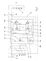
- Fig. 1 shows a circuit arrangement 10 for interposition in an electrical connection between a non-descript tractor and a trailer unspecified.
- the circuit arrangement for a single channel is shown, specifically an unspecified flashing light channel, wherein serves as a voltage source switched by a turn signal flasher terminal 12 in the cockpit of the towing vehicle.
- This is performed in the towing vehicle on a karmai solution, which is connectable via a plug connection with a terminal 16 of the circuit arrangement 10.
- the plug connection consisting of the zug mecanicter terminal 18
- the terminal 16 is a 13-pin connector, as is customary for the connection of trailers to towing vehicles.
- other lights such as brake lights, taillights and / or the like can be monitored with the circuit arrangement of the invention.
- a channel must be provided just as for the indicator light for each luminaire to be monitored.
- the circuit arrangement 10 has a connection 38 which is designed for connection to a trailer-side connection 36.
- the trailer-side terminal 36 is electrically connected to a trailer lamp 32, which in turn has a light-emitting diode arrangement as illumination means.
- the terminals 16, 38 within the circuit 10 are in electrical connection with each other. Through the resistor 40, the consumption current of the trailer lamp 32 flows.
- circuit 10 according to Fig. 1
- an incandescent lamp simulation circuit 22 and a diagnostic circuit 20 comprise.
- the circuit arrangement 10 can be expanded for further luminaire channels by providing further diagnostic and light bulb simulation circuits.
- the light bulb simulation circuit 22 has an electrical resistance 44 which is electrically connected at one terminal to the terminal 16 of the circuit arrangement and is connected with its other terminal in series with a transistor 42.
- the transistor 42 is a bipolar switching transistor.
- the transistor 42 is provided with a resistor circuit which is connected to a line 46, via which the transistor 42 and thus the bulb simulation circuit on or off.
- the circuit arrangement 10 further comprises a trailer detection circuit 50 which has an electrical resistance 54 and a switching contact 56 in series.
- the switching contact 56 can be actuated by means of a mechanical actuation 52 which can be inserted by inserting a plug housing of a trailer plug into a corresponding plug-in coupling of the circuit arrangement 10. By inserting the trailer plug, the switching contact 56 is closed, so that via the electrical resistance 54, a test potential supplied by the towing vehicle for detecting the trailer can be grounded.
- the circuit arrangement thus allows zuggenic person to perform the trailer detection without interference in the intended manner.
- the line 46 is controlled by the diagnostic circuit 20.
- the diagnostic circuit 20 supplies for this purpose via the line 46, a suitable signal by means of which the transistor 42 can be switched on or off.
- the diagnostic circuit 20 includes a current measuring unit 24 and a comparison unit 28.
- the current measuring unit 24 is presently formed by an inverting-connected operational amplifier, which measures a voltage drop at the electrical resistance 40 on the input side.
- the output signal of the operational amplifier is fed to the inverting input of another, belonging to the comparison unit 28 operational amplifier, which compares this output signal with a fixed predetermined voltage value at its positive input.
- a maximum or a minimum output voltage is established at the output of the further operational amplifier electrically connected to the line 46. This is delivered via the line 46 to the light bulb simulation circuit 22 and controls it.
- the present circuit is designed to detect interruption failure of the trailer lamp 32. If the voltage drop across the electrical resistor 40 decreases due to an interruption to the trailer lamp 32 or in the light-emitting diode arrangement 14, the current measuring unit 24 supplies a signal to the comparison unit 28 which is greater in electrical voltage than the voltage set by a voltage divider of the comparison unit 28 comparison value. In this case, the comparison unit 28 supplies as output a minimum voltage in the range of the ground potential, which is delivered by means of the line 46 to the light bulb simulation circuit 22. As a result, the transistor 42 of the light bulb simulation circuit 22 is turned off. The higher-level vehicle control detects an unacceptably low power consumption and thus detects a defect of the trailer lamp 32, which is signaled via unspecified manner a leader of the towing vehicle.
- Fig. 1 how out Fig. 1 can be seen, the operational amplifier of the current measuring unit 24 and the comparison unit 28 are supplied with electrical energy from the flashing light signal of the towing vehicle. As long as the towing vehicle at its zughus sectionen terminal 18 provides no electrical voltage, because the flashing light is not active, the entire circuit is de-energized. As a result, a particularly low energy consumption can be achieved. It should also be noted that, of course, an undesignated reference potential of the circuit arrangement 10, represented by the mass symbol in FIG Fig. 1 , is electrically connected to both a towing vehicle mass and a trailer mass. A further embodiment of the invention can be found in Fig. 2 , The embodiment according to Fig. 2 is based on the embodiment according to Fig. 1 Therefore, with regard to the relevant components and their functions to the description of the embodiment according to Fig. 1 is referenced.
- a circuit 100 in addition to the already with respect Fig. 1 discussed light bulb simulation circuit 22 includes a deactivation circuit 134 and a diagnostic circuit 120.
- the diagnostic circuit 120 has, in addition to the components already in the diagnostic circuit 20 of Fig. 1 were included, another current measuring unit 126 and a further comparison unit 130 on.
- a first current measuring unit 124 and a first comparison unit 128, a second current measuring unit 126 and a second comparison unit 130 are provided.
- the interaction of the current measuring units 124, 126 with the corresponding comparison units 128, 130 corresponds to the interaction of the current measuring unit 24 with the comparison unit 28 of FIG Fig. 1 why in this regard reference is made to the above statements.
- the function and design of the current measuring unit 124 in conjunction with the comparison unit 128 corresponds to the current measuring unit 24 in conjunction with the comparison unit 28 of the previous exemplary embodiment Fig. 1 ,
- a second switching threshold is created, which is realized by the second comparison unit 130.
- the comparison units 128, 130 have the same comparison values.
- the gain of the second current measuring unit 126 is set such that when a predefinable consumption current is exceeded, a positive signal is output from the second comparison unit 130 via a line 148 to a deactivation circuit 134.
- the deactivation circuit 134 like the light bulb simulation circuit 22, has a transistor 142 which is controllable via a resistance network by an electrical voltage on the line 148.
- the transistor 142 is likewise designed as a bipolar switching transistor whose emitter is electrically connected to the ground and whose collector is electrically connected to the line 46.
- the diagnosis circuit 120 now detects a current which is considerably greater than that of the light-emitting diode arrangement 14, the light-bulb simulation circuit 22 is deactivated via the deactivation circuit 134.
- This embodiment thus proves to be advantageous if a user or a vehicle driver unknowingly connects a light-bulb-based trailer lamp to the circuit arrangement 100 instead of a light-emitting diode-based trailer lamp 32.
- the circuit 100 is thus able to automatically detect whether a light emitting diode or an incandescent based trailer light is connected and adjusts its function accordingly.
- the lamp of the trailer may also have combined light sources of different types, so that there is a mixed operation.
- incandescent lamps and LEDs can be arranged together in a lamp of the trailer and connected to each other electrically.
- the circuit arrangement according to the invention makes it possible to reliably operate such luminaires, for example by setting the threshold values of the comparison units and / or the gains of the current measuring units accordingly. From the figures, it is not apparent that the circuit arrangements 10, 100 are mechanically formed as an adapter, which are arranged in a housing and each having a 13-pin plug-in connector and a 13-pin plug, so that the adapter in a conventional connection between a Towing vehicle and an attachments can be interposed.
Landscapes
- Engineering & Computer Science (AREA)
- Mechanical Engineering (AREA)
- Circuit Arrangement For Electric Light Sources In General (AREA)
- Lighting Device Outwards From Vehicle And Optical Signal (AREA)
Priority Applications (2)
| Application Number | Priority Date | Filing Date | Title |
|---|---|---|---|
| PL11006680T PL2390140T3 (pl) | 2007-06-01 | 2008-05-30 | Układ połączeń |
| EP11006680.0A EP2390140B1 (fr) | 2007-06-01 | 2008-05-30 | Agencement de circuit |
Applications Claiming Priority (3)
| Application Number | Priority Date | Filing Date | Title |
|---|---|---|---|
| DE202007007777U DE202007007777U1 (de) | 2007-06-01 | 2007-06-01 | Schaltungsanordnung |
| DE202007007775U DE202007007775U1 (de) | 2007-06-01 | 2007-06-01 | Anhängeranschlußgerät |
| DE202007007776U DE202007007776U1 (de) | 2007-06-01 | 2007-06-01 | Anhängeranschlußgerät |
Related Child Applications (2)
| Application Number | Title | Priority Date | Filing Date |
|---|---|---|---|
| EP11006680.0A Division-Into EP2390140B1 (fr) | 2007-06-01 | 2008-05-30 | Agencement de circuit |
| EP11006680.0A Division EP2390140B1 (fr) | 2007-06-01 | 2008-05-30 | Agencement de circuit |
Publications (2)
| Publication Number | Publication Date |
|---|---|
| EP2000358A1 true EP2000358A1 (fr) | 2008-12-10 |
| EP2000358B1 EP2000358B1 (fr) | 2016-08-03 |
Family
ID=39714165
Family Applications (2)
| Application Number | Title | Priority Date | Filing Date |
|---|---|---|---|
| EP08009904.7A Not-in-force EP2000358B1 (fr) | 2007-06-01 | 2008-05-30 | Circuit d'alimentation pour LED sur une remorque |
| EP11006680.0A Not-in-force EP2390140B1 (fr) | 2007-06-01 | 2008-05-30 | Agencement de circuit |
Family Applications After (1)
| Application Number | Title | Priority Date | Filing Date |
|---|---|---|---|
| EP11006680.0A Not-in-force EP2390140B1 (fr) | 2007-06-01 | 2008-05-30 | Agencement de circuit |
Country Status (2)
| Country | Link |
|---|---|
| EP (2) | EP2000358B1 (fr) |
| PL (2) | PL2000358T3 (fr) |
Cited By (10)
| Publication number | Priority date | Publication date | Assignee | Title |
|---|---|---|---|---|
| DE102009052690B3 (de) * | 2009-11-11 | 2011-04-28 | Osma Gmbh | Verfahren und Vorrichtung zum Betreiben von LED-Leuchten in Kraftfahrzeugen |
| EP2377723A1 (fr) | 2010-04-16 | 2011-10-19 | ConWys AG | Dispositif de reconnaissance de remorque |
| DE102010047192A1 (de) * | 2010-09-30 | 2012-04-05 | Volkswagen Ag | Verfahren und Vorrichtung zur Überprüfung einer Kopplung zwischen Zugfahrzeug und Anhänger |
| EP2648481A1 (fr) | 2012-04-03 | 2013-10-09 | Werner Rüttgerodt | Adaptateur destiné au raccordement de lampes à DEL sur une alimentation en tension dotée d'une surveillance de fonction pour lampes à incandescence |
| WO2017168179A1 (fr) * | 2016-04-01 | 2017-10-05 | Haldex Brake Products Aktiebolag | Circuit de charge de courant, système d'alimentation électrique et véhicule |
| FR3052710A1 (fr) * | 2016-06-15 | 2017-12-22 | Peugeot Citroen Automobiles Sa | Boitier d'interface entre un vehicule automobile et un vehicule tracte |
| WO2018185294A1 (fr) | 2017-04-07 | 2018-10-11 | Enganches Y Remolques Aragón, S.L. | Circuit électrique pour accessoire |
| EP3399840A1 (fr) * | 2017-05-02 | 2018-11-07 | OSRAM GmbH | Commande d'au moins un moyen d'éclairage d'un phare de véhicule en fonction d'une grandeur électrique pouvant être fournie à une borne de phare de véhicule d'un véhicule |
| AT16073U1 (de) * | 2017-11-09 | 2018-12-15 | Sanube Gmbh | Verfahren zur LED-Ansteuerung eines Fahrtrichtungsanzeigers |
| WO2021098993A1 (fr) * | 2019-11-18 | 2021-05-27 | Sparex Limited | Adaptateur d'éclairage de bus can |
Families Citing this family (1)
| Publication number | Priority date | Publication date | Assignee | Title |
|---|---|---|---|---|
| EP2677614B1 (fr) | 2012-06-20 | 2014-09-17 | Mkem, Spol s.r.o. | Boîtier destiné à la réception d'un module de suspension |
Citations (5)
| Publication number | Priority date | Publication date | Assignee | Title |
|---|---|---|---|---|
| DE10215472A1 (de) * | 2002-04-09 | 2003-11-06 | Hella Kg Hueck & Co | Verfahren zur Simulation der Stromkennlinie einer Glühlampe |
| EP1458222A1 (fr) | 2003-03-14 | 2004-09-15 | Britax PMG Limited | Dispositif avertisseur pour une lampe défectueuse |
| EP1368997B1 (fr) * | 2001-03-10 | 2006-01-11 | Siemens Plc | Appareil electrique et procede correspondant |
| DE102004045435A1 (de) * | 2004-09-18 | 2006-03-23 | Man Nutzfahrzeuge Ag | Überwachung der Funktion von Glühlampen oder LED-Leuchten in Kraftfahrzeugen |
| EP1653782A2 (fr) * | 2004-05-04 | 2006-05-03 | ASPÖCK Systems GmbH | Dispositif de contrôle de LEDs pour feux de véhicule |
-
2008
- 2008-05-30 EP EP08009904.7A patent/EP2000358B1/fr not_active Not-in-force
- 2008-05-30 EP EP11006680.0A patent/EP2390140B1/fr not_active Not-in-force
- 2008-05-30 PL PL08009904T patent/PL2000358T3/pl unknown
- 2008-05-30 PL PL11006680T patent/PL2390140T3/pl unknown
Patent Citations (5)
| Publication number | Priority date | Publication date | Assignee | Title |
|---|---|---|---|---|
| EP1368997B1 (fr) * | 2001-03-10 | 2006-01-11 | Siemens Plc | Appareil electrique et procede correspondant |
| DE10215472A1 (de) * | 2002-04-09 | 2003-11-06 | Hella Kg Hueck & Co | Verfahren zur Simulation der Stromkennlinie einer Glühlampe |
| EP1458222A1 (fr) | 2003-03-14 | 2004-09-15 | Britax PMG Limited | Dispositif avertisseur pour une lampe défectueuse |
| EP1653782A2 (fr) * | 2004-05-04 | 2006-05-03 | ASPÖCK Systems GmbH | Dispositif de contrôle de LEDs pour feux de véhicule |
| DE102004045435A1 (de) * | 2004-09-18 | 2006-03-23 | Man Nutzfahrzeuge Ag | Überwachung der Funktion von Glühlampen oder LED-Leuchten in Kraftfahrzeugen |
Cited By (13)
| Publication number | Priority date | Publication date | Assignee | Title |
|---|---|---|---|---|
| DE102009052690B3 (de) * | 2009-11-11 | 2011-04-28 | Osma Gmbh | Verfahren und Vorrichtung zum Betreiben von LED-Leuchten in Kraftfahrzeugen |
| EP2377723A1 (fr) | 2010-04-16 | 2011-10-19 | ConWys AG | Dispositif de reconnaissance de remorque |
| DE102010047192A1 (de) * | 2010-09-30 | 2012-04-05 | Volkswagen Ag | Verfahren und Vorrichtung zur Überprüfung einer Kopplung zwischen Zugfahrzeug und Anhänger |
| EP2648481A1 (fr) | 2012-04-03 | 2013-10-09 | Werner Rüttgerodt | Adaptateur destiné au raccordement de lampes à DEL sur une alimentation en tension dotée d'une surveillance de fonction pour lampes à incandescence |
| WO2017168179A1 (fr) * | 2016-04-01 | 2017-10-05 | Haldex Brake Products Aktiebolag | Circuit de charge de courant, système d'alimentation électrique et véhicule |
| FR3052710A1 (fr) * | 2016-06-15 | 2017-12-22 | Peugeot Citroen Automobiles Sa | Boitier d'interface entre un vehicule automobile et un vehicule tracte |
| WO2018185294A1 (fr) | 2017-04-07 | 2018-10-11 | Enganches Y Remolques Aragón, S.L. | Circuit électrique pour accessoire |
| EP3399840A1 (fr) * | 2017-05-02 | 2018-11-07 | OSRAM GmbH | Commande d'au moins un moyen d'éclairage d'un phare de véhicule en fonction d'une grandeur électrique pouvant être fournie à une borne de phare de véhicule d'un véhicule |
| CN108791059A (zh) * | 2017-05-02 | 2018-11-13 | 欧司朗股份有限公司 | 连接设备、控制发光机构的方法、交通工具及其探照灯 |
| US10272821B2 (en) | 2017-05-02 | 2019-04-30 | Osram Gmbh | Control of at least one lighting means of a vehicle headlight depending on an electrical quantity providable on a vehicle headlight connection of a vehicle |
| AT16073U1 (de) * | 2017-11-09 | 2018-12-15 | Sanube Gmbh | Verfahren zur LED-Ansteuerung eines Fahrtrichtungsanzeigers |
| WO2021098993A1 (fr) * | 2019-11-18 | 2021-05-27 | Sparex Limited | Adaptateur d'éclairage de bus can |
| US11987085B2 (en) | 2019-11-18 | 2024-05-21 | Sparex Limited | CAN-bus lighting adaptor |
Also Published As
| Publication number | Publication date |
|---|---|
| EP2390140A2 (fr) | 2011-11-30 |
| PL2000358T3 (pl) | 2017-02-28 |
| EP2390140A3 (fr) | 2012-01-11 |
| PL2390140T3 (pl) | 2015-12-31 |
| EP2000358B1 (fr) | 2016-08-03 |
| EP2390140B1 (fr) | 2015-07-08 |
Similar Documents
| Publication | Publication Date | Title |
|---|---|---|
| EP2390140B1 (fr) | Agencement de circuit | |
| EP2000359B1 (fr) | Agencement de circuit | |
| DE102006015053B4 (de) | LED-Blinker und Fehlerdetektionsverfahren | |
| DE19708659C1 (de) | Blinklichtsignalanlage für Kraftfahrzeuge | |
| EP2377723B1 (fr) | Dispositif de reconnaissance de remorque | |
| DE4134981A1 (de) | Schaltungsanordnung fuer ein zugfahrzeug | |
| EP2287043B1 (fr) | Système d'éclairage de véhicule doté d'une détection et d'un affichage de panne d'une lampe de véhicule à DEL | |
| DE102010038157B4 (de) | Vorrichtung zur Einordnung und/oder Erkennung der Art einer elektrischen Last | |
| EP1653782B1 (fr) | Dispositif de contrôle de LEDs pour feux de véhicule | |
| DE102009027326A1 (de) | Schaltungsanordnung zum Detektieren eines Ausfalls eines elektrischen Verbrauchers | |
| EP2633738B2 (fr) | Ensemble composé d'un appareil de commande de réseau électrique de bord et d'au moins un variateur d'éclairage d'un véhicule automobile | |
| EP1286567B1 (fr) | Dispositif d' éclairage | |
| EP2000360A1 (fr) | Appareil de raccordement de remorque | |
| DE202010005782U1 (de) | Fahrzeugleuchtenüberwachungseinrichtung | |
| DE102011113080A1 (de) | Verfahren und Vorrichtung zur Diagnose von Leuchtmitteln in einem Fahrzeug | |
| DE102012102638A1 (de) | Fahrzeugbeleuchtungssysteme mit Detektierung einer Störung in einer der Fahrzeugleuchten | |
| DE202010015919U1 (de) | Schaltungsanordnung für ein Fahrzeug | |
| DE102005063344B4 (de) | Vorrichtung zum Ansteuern von Fahrzeuglampen | |
| EP2648481B1 (fr) | Adaptateur destiné au raccordement de lampes à DEL sur une alimentation en tension dotée d'une surveillance de fonction pour lampes à incandescence | |
| WO2022033744A1 (fr) | Charge électronique destinée à être installée dans l'alimentation électrique d'un phare de véhicule | |
| DE202010016339U1 (de) | Schaltungsanordnung | |
| EP2000357A1 (fr) | Appareil de raccordement de remorque | |
| WO2020053012A1 (fr) | Dispositif d'éclairage à del comprenant une détection d'erreurs et véhicule à moteur | |
| DD238017A1 (de) | Schaltungsanordnung zur bremslichtkontrolle in kraftfahrzeugen | |
| DE202010007913U1 (de) | Nebelschlußleuchtensteuerungseinrichtung |
Legal Events
| Date | Code | Title | Description |
|---|---|---|---|
| PUAI | Public reference made under article 153(3) epc to a published international application that has entered the european phase |
Free format text: ORIGINAL CODE: 0009012 |
|
| AK | Designated contracting states |
Kind code of ref document: A1 Designated state(s): AT BE BG CH CY CZ DE DK EE ES FI FR GB GR HR HU IE IS IT LI LT LU LV MC MT NL NO PL PT RO SE SI SK TR |
|
| AX | Request for extension of the european patent |
Extension state: AL BA MK RS |
|
| 17P | Request for examination filed |
Effective date: 20090528 |
|
| AKX | Designation fees paid |
Designated state(s): AT BE BG CH CY CZ DE DK EE ES FI FR GB GR HR HU IE IS IT LI LT LU LV MC MT NL NO PL PT RO SE SI SK TR |
|
| 17Q | First examination report despatched |
Effective date: 20110824 |
|
| TPAC | Observations filed by third parties |
Free format text: ORIGINAL CODE: EPIDOSNTIPA |
|
| GRAP | Despatch of communication of intention to grant a patent |
Free format text: ORIGINAL CODE: EPIDOSNIGR1 |
|
| INTG | Intention to grant announced |
Effective date: 20160419 |
|
| GRAS | Grant fee paid |
Free format text: ORIGINAL CODE: EPIDOSNIGR3 |
|
| GRAA | (expected) grant |
Free format text: ORIGINAL CODE: 0009210 |
|
| AK | Designated contracting states |
Kind code of ref document: B1 Designated state(s): AT BE BG CH CY CZ DE DK EE ES FI FR GB GR HR HU IE IS IT LI LT LU LV MC MT NL NO PL PT RO SE SI SK TR |
|
| REG | Reference to a national code |
Ref country code: GB Ref legal event code: FG4D Free format text: NOT ENGLISH |
|
| REG | Reference to a national code |
Ref country code: CH Ref legal event code: EP Ref country code: AT Ref legal event code: REF Ref document number: 817109 Country of ref document: AT Kind code of ref document: T Effective date: 20160815 |
|
| REG | Reference to a national code |
Ref country code: IE Ref legal event code: FG4D Free format text: LANGUAGE OF EP DOCUMENT: GERMAN |
|
| REG | Reference to a national code |
Ref country code: DE Ref legal event code: R096 Ref document number: 502008014449 Country of ref document: DE |
|
| REG | Reference to a national code |
Ref country code: NL Ref legal event code: FP |
|
| REG | Reference to a national code |
Ref country code: SE Ref legal event code: TRGR |
|
| REG | Reference to a national code |
Ref country code: LT Ref legal event code: MG4D |
|
| PG25 | Lapsed in a contracting state [announced via postgrant information from national office to epo] |
Ref country code: NO Free format text: LAPSE BECAUSE OF FAILURE TO SUBMIT A TRANSLATION OF THE DESCRIPTION OR TO PAY THE FEE WITHIN THE PRESCRIBED TIME-LIMIT Effective date: 20161103 Ref country code: FI Free format text: LAPSE BECAUSE OF FAILURE TO SUBMIT A TRANSLATION OF THE DESCRIPTION OR TO PAY THE FEE WITHIN THE PRESCRIBED TIME-LIMIT Effective date: 20160803 Ref country code: HR Free format text: LAPSE BECAUSE OF FAILURE TO SUBMIT A TRANSLATION OF THE DESCRIPTION OR TO PAY THE FEE WITHIN THE PRESCRIBED TIME-LIMIT Effective date: 20160803 Ref country code: LT Free format text: LAPSE BECAUSE OF FAILURE TO SUBMIT A TRANSLATION OF THE DESCRIPTION OR TO PAY THE FEE WITHIN THE PRESCRIBED TIME-LIMIT Effective date: 20160803 Ref country code: IT Free format text: LAPSE BECAUSE OF FAILURE TO SUBMIT A TRANSLATION OF THE DESCRIPTION OR TO PAY THE FEE WITHIN THE PRESCRIBED TIME-LIMIT Effective date: 20160803 Ref country code: IS Free format text: LAPSE BECAUSE OF FAILURE TO SUBMIT A TRANSLATION OF THE DESCRIPTION OR TO PAY THE FEE WITHIN THE PRESCRIBED TIME-LIMIT Effective date: 20161203 |
|
| REG | Reference to a national code |
Ref country code: SK Ref legal event code: T3 Ref document number: E 22380 Country of ref document: SK |
|
| PG25 | Lapsed in a contracting state [announced via postgrant information from national office to epo] |
Ref country code: ES Free format text: LAPSE BECAUSE OF FAILURE TO SUBMIT A TRANSLATION OF THE DESCRIPTION OR TO PAY THE FEE WITHIN THE PRESCRIBED TIME-LIMIT Effective date: 20160803 Ref country code: GR Free format text: LAPSE BECAUSE OF FAILURE TO SUBMIT A TRANSLATION OF THE DESCRIPTION OR TO PAY THE FEE WITHIN THE PRESCRIBED TIME-LIMIT Effective date: 20161104 Ref country code: LV Free format text: LAPSE BECAUSE OF FAILURE TO SUBMIT A TRANSLATION OF THE DESCRIPTION OR TO PAY THE FEE WITHIN THE PRESCRIBED TIME-LIMIT Effective date: 20160803 Ref country code: PT Free format text: LAPSE BECAUSE OF FAILURE TO SUBMIT A TRANSLATION OF THE DESCRIPTION OR TO PAY THE FEE WITHIN THE PRESCRIBED TIME-LIMIT Effective date: 20161205 |
|
| PG25 | Lapsed in a contracting state [announced via postgrant information from national office to epo] |
Ref country code: RO Free format text: LAPSE BECAUSE OF FAILURE TO SUBMIT A TRANSLATION OF THE DESCRIPTION OR TO PAY THE FEE WITHIN THE PRESCRIBED TIME-LIMIT Effective date: 20160803 Ref country code: EE Free format text: LAPSE BECAUSE OF FAILURE TO SUBMIT A TRANSLATION OF THE DESCRIPTION OR TO PAY THE FEE WITHIN THE PRESCRIBED TIME-LIMIT Effective date: 20160803 |
|
| REG | Reference to a national code |
Ref country code: DE Ref legal event code: R097 Ref document number: 502008014449 Country of ref document: DE |
|
| PG25 | Lapsed in a contracting state [announced via postgrant information from national office to epo] |
Ref country code: DK Free format text: LAPSE BECAUSE OF FAILURE TO SUBMIT A TRANSLATION OF THE DESCRIPTION OR TO PAY THE FEE WITHIN THE PRESCRIBED TIME-LIMIT Effective date: 20160803 Ref country code: BG Free format text: LAPSE BECAUSE OF FAILURE TO SUBMIT A TRANSLATION OF THE DESCRIPTION OR TO PAY THE FEE WITHIN THE PRESCRIBED TIME-LIMIT Effective date: 20161103 |
|
| PLBE | No opposition filed within time limit |
Free format text: ORIGINAL CODE: 0009261 |
|
| STAA | Information on the status of an ep patent application or granted ep patent |
Free format text: STATUS: NO OPPOSITION FILED WITHIN TIME LIMIT |
|
| 26N | No opposition filed |
Effective date: 20170504 |
|
| PG25 | Lapsed in a contracting state [announced via postgrant information from national office to epo] |
Ref country code: LU Free format text: LAPSE BECAUSE OF NON-PAYMENT OF DUE FEES Effective date: 20170531 Ref country code: SI Free format text: LAPSE BECAUSE OF FAILURE TO SUBMIT A TRANSLATION OF THE DESCRIPTION OR TO PAY THE FEE WITHIN THE PRESCRIBED TIME-LIMIT Effective date: 20160803 |
|
| REG | Reference to a national code |
Ref country code: CH Ref legal event code: PL |
|
| PG25 | Lapsed in a contracting state [announced via postgrant information from national office to epo] |
Ref country code: MC Free format text: LAPSE BECAUSE OF FAILURE TO SUBMIT A TRANSLATION OF THE DESCRIPTION OR TO PAY THE FEE WITHIN THE PRESCRIBED TIME-LIMIT Effective date: 20160803 |
|
| REG | Reference to a national code |
Ref country code: DE Ref legal event code: R082 Ref document number: 502008014449 Country of ref document: DE Representative=s name: RAUSCH WANISCHECK-BERGMANN BRINKMANN PARTNERSC, DE |
|
| REG | Reference to a national code |
Ref country code: IE Ref legal event code: MM4A |
|
| PG25 | Lapsed in a contracting state [announced via postgrant information from national office to epo] |
Ref country code: CH Free format text: LAPSE BECAUSE OF NON-PAYMENT OF DUE FEES Effective date: 20170531 Ref country code: LI Free format text: LAPSE BECAUSE OF NON-PAYMENT OF DUE FEES Effective date: 20170531 |
|
| REG | Reference to a national code |
Ref country code: FR Ref legal event code: ST Effective date: 20180131 |
|
| PG25 | Lapsed in a contracting state [announced via postgrant information from national office to epo] |
Ref country code: LU Free format text: LAPSE BECAUSE OF NON-PAYMENT OF DUE FEES Effective date: 20170530 |
|
| REG | Reference to a national code |
Ref country code: BE Ref legal event code: MM Effective date: 20170531 |
|
| PG25 | Lapsed in a contracting state [announced via postgrant information from national office to epo] |
Ref country code: IE Free format text: LAPSE BECAUSE OF NON-PAYMENT OF DUE FEES Effective date: 20170530 |
|
| PG25 | Lapsed in a contracting state [announced via postgrant information from national office to epo] |
Ref country code: FR Free format text: LAPSE BECAUSE OF NON-PAYMENT OF DUE FEES Effective date: 20170531 |
|
| REG | Reference to a national code |
Ref country code: AT Ref legal event code: MM01 Ref document number: 817109 Country of ref document: AT Kind code of ref document: T Effective date: 20170530 |
|
| PGFP | Annual fee paid to national office [announced via postgrant information from national office to epo] |
Ref country code: CZ Payment date: 20180529 Year of fee payment: 11 Ref country code: SK Payment date: 20180529 Year of fee payment: 11 |
|
| PG25 | Lapsed in a contracting state [announced via postgrant information from national office to epo] |
Ref country code: BE Free format text: LAPSE BECAUSE OF NON-PAYMENT OF DUE FEES Effective date: 20170531 Ref country code: AT Free format text: LAPSE BECAUSE OF NON-PAYMENT OF DUE FEES Effective date: 20170530 |
|
| PGFP | Annual fee paid to national office [announced via postgrant information from national office to epo] |
Ref country code: NL Payment date: 20180518 Year of fee payment: 11 Ref country code: PL Payment date: 20180419 Year of fee payment: 11 |
|
| PG25 | Lapsed in a contracting state [announced via postgrant information from national office to epo] |
Ref country code: MT Free format text: LAPSE BECAUSE OF FAILURE TO SUBMIT A TRANSLATION OF THE DESCRIPTION OR TO PAY THE FEE WITHIN THE PRESCRIBED TIME-LIMIT Effective date: 20160803 |
|
| PGFP | Annual fee paid to national office [announced via postgrant information from national office to epo] |
Ref country code: SE Payment date: 20180518 Year of fee payment: 11 |
|
| PGFP | Annual fee paid to national office [announced via postgrant information from national office to epo] |
Ref country code: DE Payment date: 20180727 Year of fee payment: 11 Ref country code: GB Payment date: 20180518 Year of fee payment: 11 |
|
| PG25 | Lapsed in a contracting state [announced via postgrant information from national office to epo] |
Ref country code: HU Free format text: LAPSE BECAUSE OF FAILURE TO SUBMIT A TRANSLATION OF THE DESCRIPTION OR TO PAY THE FEE WITHIN THE PRESCRIBED TIME-LIMIT; INVALID AB INITIO Effective date: 20080530 |
|
| PG25 | Lapsed in a contracting state [announced via postgrant information from national office to epo] |
Ref country code: CY Free format text: LAPSE BECAUSE OF NON-PAYMENT OF DUE FEES Effective date: 20160803 |
|
| REG | Reference to a national code |
Ref country code: DE Ref legal event code: R119 Ref document number: 502008014449 Country of ref document: DE |
|
| REG | Reference to a national code |
Ref country code: NL Ref legal event code: MM Effective date: 20190601 |
|
| GBPC | Gb: european patent ceased through non-payment of renewal fee |
Effective date: 20190530 |
|
| PG25 | Lapsed in a contracting state [announced via postgrant information from national office to epo] |
Ref country code: SE Free format text: LAPSE BECAUSE OF NON-PAYMENT OF DUE FEES Effective date: 20190531 Ref country code: CZ Free format text: LAPSE BECAUSE OF NON-PAYMENT OF DUE FEES Effective date: 20190530 Ref country code: SK Free format text: LAPSE BECAUSE OF NON-PAYMENT OF DUE FEES Effective date: 20190530 |
|
| REG | Reference to a national code |
Ref country code: SK Ref legal event code: MM4A Ref document number: E 22380 Country of ref document: SK Effective date: 20190530 |
|
| PG25 | Lapsed in a contracting state [announced via postgrant information from national office to epo] |
Ref country code: TR Free format text: LAPSE BECAUSE OF FAILURE TO SUBMIT A TRANSLATION OF THE DESCRIPTION OR TO PAY THE FEE WITHIN THE PRESCRIBED TIME-LIMIT Effective date: 20160803 |
|
| PG25 | Lapsed in a contracting state [announced via postgrant information from national office to epo] |
Ref country code: GB Free format text: LAPSE BECAUSE OF NON-PAYMENT OF DUE FEES Effective date: 20190530 Ref country code: DE Free format text: LAPSE BECAUSE OF NON-PAYMENT OF DUE FEES Effective date: 20191203 Ref country code: NL Free format text: LAPSE BECAUSE OF NON-PAYMENT OF DUE FEES Effective date: 20190601 |
|
| REG | Reference to a national code |
Ref country code: SE Ref legal event code: EUG |
|
| PG25 | Lapsed in a contracting state [announced via postgrant information from national office to epo] |
Ref country code: PL Free format text: LAPSE BECAUSE OF NON-PAYMENT OF DUE FEES Effective date: 20190530 |