EP2000571B1 - Machine à coudre et méthode pour la faire fonctionner - Google Patents
Machine à coudre et méthode pour la faire fonctionner Download PDFInfo
- Publication number
- EP2000571B1 EP2000571B1 EP08009867.6A EP08009867A EP2000571B1 EP 2000571 B1 EP2000571 B1 EP 2000571B1 EP 08009867 A EP08009867 A EP 08009867A EP 2000571 B1 EP2000571 B1 EP 2000571B1
- Authority
- EP
- European Patent Office
- Prior art keywords
- feed
- adjustment
- sewing
- fabric
- feeder
- Prior art date
- Legal status (The legal status is an assumption and is not a legal conclusion. Google has not performed a legal analysis and makes no representation as to the accuracy of the status listed.)
- Active
Links
Images


Classifications
-
- D—TEXTILES; PAPER
- D05—SEWING; EMBROIDERING; TUFTING
- D05B—SEWING
- D05B27/00—Work-feeding means
- D05B27/02—Work-feeding means with feed dogs having horizontal and vertical movements
- D05B27/04—Work-feeding means with feed dogs having horizontal and vertical movements arranged above the workpieces
-
- D—TEXTILES; PAPER
- D05—SEWING; EMBROIDERING; TUFTING
- D05B—SEWING
- D05B27/00—Work-feeding means
-
- D—TEXTILES; PAPER
- D05—SEWING; EMBROIDERING; TUFTING
- D05B—SEWING
- D05B35/00—Work-feeding or -handling elements not otherwise provided for
-
- D—TEXTILES; PAPER
- D05—SEWING; EMBROIDERING; TUFTING
- D05B—SEWING
- D05B69/00—Driving-gear; Control devices
- D05B69/20—Control devices responsive to the number of stitches made
Definitions
- the invention relates to a sewing machine with a transport device for the intermittent feed of sewing material according to the preamble of claim 1. Furthermore, the invention relates to various operating methods for such a sewing machine.
- a sewing machine of the type mentioned is known from the EP 0 512 145 B1 , There, a stitch length adjustment is described by corresponding change of feed values of an upper and a lower conveyor.
- From the US 4,867,082 is a sewing machine with an upper feed dog and two lower conveyors known.
- a transport feed of the upper transporter can be adjusted via an adjusting device with an actuator and a guided holder.
- Feed lengths of the two lower conveyors can be adjusted via corresponding actuators.
- the actuators for the upper feed dog and the lower feeders each have an adjustment motor.
- the actuators of the upper conveyor and the lower conveyors are in signal communication with a controller to which a memory belongs. Stored setting data are used to control the actuators of the upper conveyor and the lower conveyors during the execution of a sewing sequence.
- the control device can be in signal communication with external sensors and / or enable direct influencing of the adjusting drives by operating elements of the sewing machine, for example foot switches, toggle levers or pushbuttons.
- the control device can be in signal communication with external sensors and / or enable direct influencing of the adjusting drives by operating elements of the sewing machine, for example foot switches, toggle levers or pushbuttons.
- such a feed length adjustment can take place over an entire sewing sequence, wherein in each case the corresponding setting data for the adjusting drives are called up.
- an adjustment of the feed Changing sewing material parameters, for example a changing composition of the fabric or a change in the sewing direction relative to the angle of the warp and weft threads of the sewing material, are possible.
- a different ratio of the feed lengths between the upper and the lower feed dog can also be specified, which is also referred to below as the Raff feed value.
- the change in the feed length can also be used to achieve desired optical effects during sewing.
- the mechanical top feed adjusting device and the mechanical bottom feed adjusting device are designed as link adjustments and have at least one adjusting device adjustable along the adjusting link.
- Such gate adjustments as adjusting devices have proven themselves because of their mechanical robustness.
- At least one of the adjusting devices has a rotatably driven via the associated adjustment cam plate having a peripheral surface with varying radius in peripheral sections, with the peripheral surface of an adjusting body sections to Vorschubinver ein cooperates, which is mechanically coupled to the associated feed dog.
- Such adjustment can be structurally integrated into a sewing machine with little effort.
- a stepper motor according to claim 3 allows a finely predetermined feed adjustment.
- An accommodation of the adjusting drive according to claim 4 leads to a compact sewing machine.
- An embodiment according to claim 5 enables an automatic adjustment of the thread tension, in particular to a predetermined length of the control device stitch length.
- Another object of the invention is to provide operating methods for the sewing machine according to the invention.
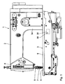
- a sewing machine 1 has an arm 2, a base plate 3, and a stand 3a connecting them.
- the free end of the arm 2 carries a head 4.
- an arm shaft 5 is mounted, which is rotatably driven by a main drive not shown in detail.
- needle bar 6 is vertically moved up and down.
- a needle 7 is mounted at the lower end of the needle bar 6.
- the needle 7 passes through a stitch hole in a throat plate 8, which is inserted into a support plate 9 of the base plate 3.
- Below the needle plate 8 a co-operating with the needle 7 for looping gripper is arranged, which is driven by a gripper shaft and a deflection gear, which are not shown in detail.
- the drive of the gripper is also derived from the arm shaft 5.
- a fabric presser 11 which is mounted at the lower end of a Stoffdrückerstange 12.
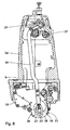
- a transport device 14 For intermittent feed of the material in a sewing direction 13, with an arrow in the Fig. 12 is shown and in the Fig. 12 extends from right to left, serves a transport device 14, whose frictionally cooperating with the material conveyors increased in the Fig. 12 are shown. With an upper surface of the fabric acts an upper Transporter 15 together, in the Fig. 12 on the one hand shown in a zero position and on the other hand at 15 'in one of these opposite to the left displaced maximum stroke position.
- the two lower conveyors 16, 17 have along the sewing direction 13 spaced-apart contact portions for frictional feed contact with the fabric underside.
- the transporters 16, 17 are shown on the one hand in a zero position and on the other hand at 16 ', 17' in a relation to this left displaced maximum stroke position.
- the transporters 15 to 17 each have a sawtooth profiling 18a.
- the stroke of all three transporters 15 to 17 in the sewing direction can be set individually for each of the transporters 15 to 17 controlled. This will be described below in connection with the feed length of one of the lower transporters 16, 17 on the basis of Fig. 7 to 11 explained.
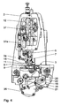
- a first stepper motor 18 which is fixedly mounted on the base plate 3.
- the first stepper motor 18 is operatively connected to the first lower feed dog 16.
- a contact body 19 Connected to a drive shaft of the first stepping motor 18 in a rotationally fixed manner is a contact body 19 with a spiral-shaped outer peripheral abutment wall 20.
- the abutment wall 20 thus has a radius varying in circumferential sections.
- the contact body 19 is a driven rotatable cam.
- the abutment wall 20 abuts an adjusting or counter body in the form of a needle bearing 21, which is held in a fork-shaped deflecting rod 22.
- the needle bearing 21 thus represents a sliding body for cooperation with the abutment wall 20.
- the deflection bar 22 is connected via a hinge 23 with a link adjusting body 24, which in turn is rotatably connected to a slotted guide 25. Along the latter is a sliding block 26 displaced. This is in turn connected to a triangular lever 27. About an eccentric shaft 28 of the triangle lever 27 is vibrated. Depending on the guide direction of the slotted guide 25, this vibration is implemented in a more or less large torsional vibration of a transmission shaft 29 about its longitudinal axis.
- FIG. 7 and FIGS. 10 and 11 show a lower feed adjusting device 30, to which the first stepping motor 18 belongs, in a "small lift" position in which practically no angular displacement is transmitted to the transmission shaft 29 during operation.
- the assigned lower transporter When operating the sewing machine, the assigned lower transporter remains virtually in its zero position. In the "small stroke” position, the outermost end of the abutment wall 20 bears against the needle bearing 21, so that the latter is maximally spaced from the drive shaft of the first stepping motor 18.
- the 8 and 9 In contrast, show the position "long stroke" of the first lower feed adjustment 30. In this position “large stroke” the abutment wall 20 is at its innermost end on the needle bearing 21, so that the distance between this and the drive shaft of the stepping motor 18 is low. Between the two positions “small stroke” and “large stroke” is a relative rotation of the drive shaft of the first Stepping motor 18 of about 225 °. Since the stepper motor 18 has a high step resolution, all intermediate positions between the positions "small stroke” and "large stroke” can be practically infinitely preset.
- a second lower transport adjustment device 31 is used for controlled specification of the feed length of the second lower conveyor 17.
- the second lower transport adjustment device 31 has a second stepper motor 32, which is also mounted on the base plate 3 under the support plate 9.
- the second stepper motor 32 is operatively connected to the second lower feed dog 17.
- the mechanical actuation of the second lower feed adjusting device 31 corresponds to that of the first lower feed adjusting device 30 and has the same structure as this, with the difference that the second Untes transport adjustment device 31 on a transmission shaft 33 acts, which runs in the executed as a hollow shaft transmission shaft 29 of the first lower feed adjustment device 30 and is rotated independently of this about a common longitudinal axis of the two shafts 29, 33 by a predetermined angular amount to the feed control.
- the transmission shafts 29, 33 act independently of one another on each of the lower conveyors 16 and 17.
- the feed length of the lower feed conveyor controlled by the second lower feed adjusting device 31 can be preset via the rotation of the second stepping motor 32, as described above in connection with FIG the first lower feed adjusting device 30 has been explained.
- the Fig. 5 shows the second lower feed adjusting device 31 in a position similar to that of the first lower feed adjusting device 30 after the 10 and 11 corresponds, ie in the position "small stroke".
- the second lower feed adjusting device 31 can be practically continuously changed to the "long stroke" position.
- an upper transport adjustment 34 To adjust a feed length of the upper conveyor 15 is an upper transport adjustment 34.
- This has a third stepper motor 35, which is also mounted on the base plate 3 and mounted under the support plate 9.
- the third stepping motor 35 is in operative connection with the upper conveyor 15.
- the mechanical transmission from the stepping motor 35 to the upper feed dog 15 corresponds to that which has been explained above with reference to the two lower feed adjusting devices 30, 31.
- the upper transport adjusting device 34 has as a transfer member between the needle roller bearing 21 and the guide adjusting body 24 a pull rod 36, which extends in the stator 3a.
- a corresponding angular displacement is imparted to a transmission shaft 37 of the top feed adjusting device 34, which in turn is mechanically connected to the upper feed dog 15 via a push rod 37a.
- the transmission shaft 37 runs along the arm 2.
- the three stepper motors 18, 32, 35 are all housed within a housing surrounding the base plate 3 and not shown in the drawing of the sewing machine.
- control device 38 is connected to the two lower feed adjustment devices 30, 31 and the upper transport adjustment device 34 in signal connection.
- the control device 38 has a memory device 39, in which data to be processed sewing sequences and this sewing sequence data associated adjustment data for controlling the stepper motors 18, 32, 35 are stored during the execution of the sewing sequence.
- a first feed value for advancing the material to be sewn by the transporters 15 to 17 is initially predetermined by corresponding synchronous control of all three stepper motors 18, 32, 35, controlled by the control device 38. Subsequently, the sewing material, as long as this first default value is set, so with a first stitch length, sewn. Subsequently, a second, from the first different feed value to the material feed with the transporters 15 to 17 by concurrently driving the stepper motors 18, 32, 35 predetermined. Subsequently, the sewing material is sewn with the resulting second feed value, which may for example be greater than the first feed value, so that the subsequent seam has a greater stitch length than before.
- This controlled conversion of the feed value can be done, for example, depending on detected signal values of additional sensors on the sewing machine 1, for example a light barrier sensor or a touch sensor, which detects when one end of the material is reached and therefore only a few stitches are to be sewed to the seam end, so that it is ensured by appropriate adjustment of the stitch length that the last stitch ends at a predetermined location, without this last stitch in its length being too different from the previous stitches. Such a difference is undesirable for optical reasons. Even when sewing corner stitching this can be a stitch shortening can be prevented in the corner.
- the thread tension is automatically adjusted, controlled by the control device 38.
- the control device 38 controls an electronic thread tension transmitter of the sewing machine 1.
- the thread tension is increased in particular as the stitch length is increased.
- a first Raff feed value for advancing the material to be conveyed with the transporters 15 to 17, wherein the upper conveyor 15 z. B. makes a material feed, which is different from the Nähgutvorschub the lower conveyors 16, 17. Subsequently, the fabric is sewn with this first Raff feed value. Subsequently, by appropriate adjustment of either the stepping motor 35 for the upper conveyor 15 or concurrent adjustment of the stepper motors 18, 32 for the two lower conveyors 16, 17, a second, predetermined by the first Raff feed value.
- the differential is utilized.
- This is first a first crimp feed value for advancing the material to be sewn with the two lower transporters 16, 17, wherein z. B. the first lower feed dog 16 performs a Nähgutvorschub different from the Nähgutvorschub the second lower conveyor 17.
- the feed supplied by the second lower feed dog 17 is slightly larger than that supplied by the first lower feed dog 16. The fabric is now sewn with this first crimp feed value.
- a second crimp feed value is predetermined, which differs from the first crimp feed value.
- the conversion can for example be such that the difference in the feed between the two lower conveyors 16, 17 is now greater than before, so that the lower work piece is now crimped by the two lower conveyors 16, 17 more.
- the fabric is sewn with the second crimp feed value.
- This third method of operation can also be used to achieve certain optical results when sewing or to compensate for a change in the properties of the material during sewing, in particular when sewing seams with changes in direction.
- Changes in sewing material parameters are, for example, changes in the type of binding of the sewing material, changes in the raw material composition of the sewing material or changes in the degree of twist of the warp and weft threads with each other.
- the control of the stepper motors 18, 32, 35 can automatically by the controller 38 when executing a sewing program or a Sewing sequence done.
- this control directly, for example via a foot switch or a toggle or a button by the operator.
- the operator can therefore change the stitch length, the differentiability or the differential as needed during sewing.
- Such a direct control is possible in particular for making quick corrections, which is often desirable, for example, when sewing in sleeves.
- blank tolerances can be compensated.
- this can also be done depending on internal parameters, for example the number of sewn stitches or the sewn seam length.
Landscapes
- Engineering & Computer Science (AREA)
- Textile Engineering (AREA)
- Mechanical Engineering (AREA)
- Sewing Machines And Sewing (AREA)
Claims (8)
- Machine à coudre (1)- comprenant un équipement de transport (14) destiné à l'avancement intermittent de la pièce à coudre, comprenant-- au moins un système transporteur supérieur (15) pour un contact d'avancement par friction intermittent avec la partie supérieure de la pièce à coudre,-- au moins un système transporteur inférieur (16, 17) pour un contact d'avancement par friction intermittent avec la partie inférieure de la pièce à coudre,- comprenant un dispositif de réglage mécanique de transport supérieur (34) destiné au réglage d'une longueur d'avancement de l'au moins un système transporteur supérieur (15),- comprenant un dispositif de réglage mécanique de transport inférieur (30, 31) pour le réglage d'une longueur d'avancement de l'au moins un système transporteur inférieur (16, 17),- comprenant un entraînement de réglage du transport supérieur (35) pour le réglage du dispositif de réglage de transport supérieur (34),- comprenant un entraînement de réglage du transport inférieur (18, 32) pour le réglage du dispositif de réglage de transport inférieur (30, 31),comprenant une installation de réglage (38) qui est en relation par signal avec l'entraînement de réglage de transport inférieur (18, 32) et avec l'entraînement de réglage de transport supérieur (35) et présente une mémoire (39) dans laquelle les données des séquences de couture à effectuer et les données de réglage correspondant à ces séquences de couture sont consignées pour le démarrage indépendant des entraînements de réglage (18, 32, 35) pendant le déroulement de la séquence de couture,- les dispositifs de réglages (30, 31, 34) étant conçus sous la forme de réglages à coulisse et présentant au moins un corps de réglage à coulisse (24) réglable le long du dispositif de réglage (18, 32, 35),- au moins l'un des dispositifs de réglage (30, 31, 34) présentant une came rotative (19), entraînée par l'intermédiaire d'un entraînement de réglage (18, 32, 34) associé, cette came comportant une surface circonférentielle (20) en forme de spirale avec un rayon variant sur des portions de circonférence, un corps de réglage (21) qui est couplé mécaniquement avec le système transporteur associé (15 à 17), agissant conjointement avec la surface circonférentielle (20) pour le réglage des longueurs d'avancement.
- Machine à coudre selon la revendication 1 caractérisée en ce que l'équipement de transport (14) comprend en outre :- au moins un autre système transporteur inférieur (17, 16) pour le contact d'avancement par friction intermittent avec la partie inférieure de la pièce à coudre,- les deux systèmes transporteurs inférieurs (16, 17) présentant des sections de contact espacées les unes des autres le long d'une direction de couture (13) pour le contact d'avancement avec la partie inférieure de la pièce à coudre,- comprenant un autre dispositif de réglage mécanique de transport inférieur (31, 30) pour le réglage d'une longueur d'avancement de l'autre système transporteur inférieur (17, 16),- comprenant un autre entraînement de réglage de transport inférieur (35, 32) pour le réglage de l'autre dispositif de réglage du transport inférieur (31, 30),- l'installation de réglage (38) étant également en liaison par signal avec l'autre dispositif de réglage de transport inférieur (31, 30), et- avec en fonction des données des séquences de couture à exécuter, un stockage dans la mémoire (39) de nouvelles données de réglage pour démarrer également l'autre entraînement de réglage du transport inférieur (35, 32) pendant le déroulement de la séquence de couture.
- Machine à coudre selon l'une des revendications 1 à 2 caractérisée par un moteur pas à pas (18, 32, 35) servant d'entraînement de réglage.
- Machine à coudre selon l'une des revendications de 1 à 3 caractérisée en ce qu'au moins un entraînement de réglage (18, 32, 35) est logé dans un carter de la machine à coudre (1).
- Machine à coudre selon l'une des revendications de 1 à 4 caractérisée en ce que l'installation de réglage (38) est reliée avec un tendeur.
- Méthode de fonctionnement d'une machine à coudre selon l'une des revendications de 1 à 5, comprenant les étapes suivantes :- prescription d'une première valeur d'avancement pour l'avancement de la pièce à coudre avec l'au moins un système transporteur supérieur (15) et l'au moins un système transporteur inférieur (16, 17),- couture de la pièce à coudre avec une première valeur d'avancement,- prescription d'une deuxième valeur d'avancement, différente de la première, pour l'avancement de la pièce à coudre avec l'au moins un système transporteur supérieur (15) et l'au moins un système transporteur inférieur (16, 17),- couture de la pièce à coudre avec la deuxième valeur d'avancement.
- Méthode de fonctionnement d'une machine à coudre selon l'une des revendications de 1 à 5, comprenant les étapes suivantes :- prescription d'une première valeur d'avancement de plissage pour l'avancement de la pièce à coudre avec l'au moins un système transporteur supérieur (15) et l'au moins un système transporteur inférieur (16, 17), la première valeur d'avancement de plissage correspondant au rapport des longueurs d'avancement du système transporteur supérieur (15) et du système transporteur inférieur (16, 17),- couture de la pièce à coudre avec la première valeur d'avancement de plissage,- prescription d'une deuxième valeur d'avancement de plissage, différente de la première, pour l'avancement de la pièce à coudre avec l'au moins un système transporteur (15) supérieur et avec l'au moins un système transporteur inférieur (16, 17),- couture de la pièce à coudre avec la deuxième valeur d'avancement de plissage.
- Méthode de fonctionnement d'une machine à coudre selon la revendication 2 ou selon l'une des revendications de 3 à 5, lorsqu'elles sont au moins dépendantes de la revendication 2, comprenant les étapes suivantes :- prescription d'une première valeur d'avancement de fronçage pour l'avancement de la pièce à coudre avec les deux systèmes transporteurs inférieurs (16, 17), la première valeur d'avancement de fronçage correspondant au rapport des longueurs d'avancement du système transporteur inférieur (16) et de l'autre système transporteur inférieur (17),- couture de la pièce à coudre avec la première valeur d'avancement de fronçage,- prescription d'une deuxième valeur d'avancement de fronçage, différente de la première, pour l'avancement de la pièce à coudre avec les deux systèmes transporteurs inférieurs (16, 17),- couture de la pièce à coudre avec la deuxième valeur d'avancement de fronçage.
Applications Claiming Priority (1)
| Application Number | Priority Date | Filing Date | Title |
|---|---|---|---|
| DE102007026651A DE102007026651A1 (de) | 2007-06-08 | 2007-06-08 | Nähmaschine sowie Betriebsverfahren für eine derartige Nähmaschine |
Publications (3)
| Publication Number | Publication Date |
|---|---|
| EP2000571A2 EP2000571A2 (fr) | 2008-12-10 |
| EP2000571A3 EP2000571A3 (fr) | 2011-06-22 |
| EP2000571B1 true EP2000571B1 (fr) | 2013-11-06 |
Family
ID=39811628
Family Applications (1)
| Application Number | Title | Priority Date | Filing Date |
|---|---|---|---|
| EP08009867.6A Active EP2000571B1 (fr) | 2007-06-08 | 2008-05-30 | Machine à coudre et méthode pour la faire fonctionner |
Country Status (5)
| Country | Link |
|---|---|
| EP (1) | EP2000571B1 (fr) |
| JP (2) | JP2008302222A (fr) |
| KR (2) | KR20080108035A (fr) |
| CN (1) | CN101319436B (fr) |
| DE (1) | DE102007026651A1 (fr) |
Cited By (1)
| Publication number | Priority date | Publication date | Assignee | Title |
|---|---|---|---|---|
| TWI596250B (zh) * | 2015-06-02 | 2017-08-21 | Zeng Hsing Industrial Co Ltd | Sewing machine feed feed compensation method |
Families Citing this family (9)
| Publication number | Priority date | Publication date | Assignee | Title |
|---|---|---|---|---|
| DE102008030797A1 (de) * | 2008-06-28 | 2009-12-31 | Dürkopp Adler AG | Nähmaschine sowie Verfahren zum Betrieb einer derartigen Nähmaschine |
| JP5522981B2 (ja) * | 2009-06-18 | 2014-06-18 | 日本発條株式会社 | 縫製装置の下側送り機構および縫製装置 |
| DE102011052521B4 (de) | 2011-08-09 | 2023-02-23 | Chee Siang Industrial Co., Ltd. | Säulennähmaschine |
| CN105734841B (zh) * | 2014-12-08 | 2018-04-10 | 曾贤长 | 缝纫机的送布齿差动机构 |
| CH712437A1 (de) | 2016-05-06 | 2017-11-15 | Bernina Int Ag | Nähmaschine umfassend eine Vorrichtung zum manuellen Wechseln eines Transporteurs. |
| CN105803692A (zh) * | 2016-05-22 | 2016-07-27 | 贵州大学 | 一种缝纫裁布装置的控制装置 |
| DE102017206499B3 (de) * | 2017-04-18 | 2018-05-03 | Dürkopp Adler AG | Nähmaschine |
| DE102017216725A1 (de) * | 2017-09-21 | 2019-03-21 | Dürkopp Adler AG | Verfahren zum Betrieb einer Nähmaschine sowie Nähmaschine zur Durchführung des Verfahrens |
| CN110552120B (zh) * | 2019-09-10 | 2022-03-25 | 杰克科技股份有限公司 | 一种绷缝机的自动调节针距结构 |
Family Cites Families (13)
| Publication number | Priority date | Publication date | Assignee | Title |
|---|---|---|---|---|
| JPS56163689A (en) * | 1980-05-22 | 1981-12-16 | Mitsubishi Electric Corp | Sewing machine. feeding thereof can be adjusted |
| DE3216993C2 (de) * | 1982-05-06 | 1989-03-16 | Pfaff Industriemaschinen Gmbh, 6750 Kaiserslautern | Nähmaschine mit einer Einrichtung zum Herstellen von Formnähten |
| IL78944A (en) * | 1985-06-03 | 1990-04-29 | Prouvost Sa | Method and sewing machine for automatically providing end of stitching at a given distance from the edge of a piece of fabric |
| DE3627470A1 (de) * | 1986-08-13 | 1988-02-18 | Pfaff Ind Masch | Verfahren zum naehen der ecke einer doppelnaht mit einer zweinadelnaehmaschine |
| IT1217796B (it) * | 1988-06-07 | 1990-03-30 | Rockwell Rimoldi Spa | Dispositivo elettronico per la gestione dell'autosetting in macchine per cucire industriali. |
| EP0512145B1 (fr) | 1991-05-10 | 1994-01-12 | Dürkopp Adler Aktiengesellschaft | Procédé pour exécuter une couture changeant de direction |
| JPH0759970A (ja) * | 1993-08-25 | 1995-03-07 | Brother Ind Ltd | 差動送りミシン |
| DE19920350C1 (de) * | 1999-05-04 | 2000-11-30 | Duerkopp Adler Ag | Verfahren zum Betrieb einer Nähmaschine zum Verbinden eines ersten Nähgutteils mit einem zweiten Nähgutteil unter Einarbeitung von Mehrweite |
| JP3867012B2 (ja) * | 2002-05-14 | 2007-01-10 | Juki株式会社 | ミシンの布送り装置 |
| JP4509491B2 (ja) * | 2003-04-21 | 2010-07-21 | Juki株式会社 | 差動送りミシン |
| JP4608998B2 (ja) * | 2004-08-23 | 2011-01-12 | ブラザー工業株式会社 | パターン縫いミシン及びその布送り方法 |
| JP4364115B2 (ja) * | 2004-12-03 | 2009-11-11 | Juki株式会社 | ミシン |
| JP2006263177A (ja) * | 2005-03-24 | 2006-10-05 | Juki Corp | ミシン |
-
2007
- 2007-06-08 DE DE102007026651A patent/DE102007026651A1/de not_active Withdrawn
-
2008
- 2008-05-30 EP EP08009867.6A patent/EP2000571B1/fr active Active
- 2008-06-03 JP JP2008145743A patent/JP2008302222A/ja active Pending
- 2008-06-05 KR KR1020080053002A patent/KR20080108035A/ko not_active Withdrawn
- 2008-06-10 CN CN2008101101184A patent/CN101319436B/zh active Active
-
2012
- 2012-12-14 JP JP2012007570U patent/JP3181916U/ja not_active Expired - Fee Related
-
2014
- 2014-03-25 KR KR2020140002336U patent/KR200475371Y1/ko not_active Expired - Fee Related
Cited By (1)
| Publication number | Priority date | Publication date | Assignee | Title |
|---|---|---|---|---|
| TWI596250B (zh) * | 2015-06-02 | 2017-08-21 | Zeng Hsing Industrial Co Ltd | Sewing machine feed feed compensation method |
Also Published As
| Publication number | Publication date |
|---|---|
| KR20080108035A (ko) | 2008-12-11 |
| KR20140002775U (ko) | 2014-05-09 |
| CN101319436B (zh) | 2013-04-24 |
| EP2000571A2 (fr) | 2008-12-10 |
| JP3181916U (ja) | 2013-02-28 |
| EP2000571A3 (fr) | 2011-06-22 |
| KR200475371Y1 (ko) | 2014-11-26 |
| JP2008302222A (ja) | 2008-12-18 |
| CN101319436A (zh) | 2008-12-10 |
| DE102007026651A1 (de) | 2008-12-18 |
Similar Documents
| Publication | Publication Date | Title |
|---|---|---|
| EP2000571B1 (fr) | Machine à coudre et méthode pour la faire fonctionner | |
| DE102007031072B4 (de) | Nähmaschine | |
| DE102008051626B4 (de) | Nähgutvorschubvorrichtung einer Nähmaschine | |
| EP2138620B1 (fr) | Machine à coudre et procédé de fonctionnement d'une telle machine à coudre | |
| DE102017107281A1 (de) | Nähmaschine | |
| DE3216993A1 (de) | Naehmaschine mit einer einrichtung zum herstellen von formnaehten | |
| DE4230163A1 (de) | Verfahren und vorrichtung zum steuern der randposition eines textilstuecks | |
| DE3832124A1 (de) | Elektronische vorrichtung fuer die automatische einstellung von industrie-naehmaschinen | |
| DE8533380U1 (de) | Nähmaschine mit Differentialvorschub | |
| DE102009004217A1 (de) | Zwei-Nadel-Nähmaschine | |
| DE10321266B4 (de) | Nähgutzuführvorrichtung | |
| DE10002456B4 (de) | Stoffvorschubvorrichtung für Nähmaschine | |
| DE19624260A1 (de) | Nähmaschine | |
| DE10262180B4 (de) | Fadenspanner | |
| DE19611793B4 (de) | Fadenschneider für eine Kettenstich-Nähmaschine | |
| DE202009000251U1 (de) | Nähmaschine | |
| DE102006057581A1 (de) | Nähmaschine | |
| DE2317975C3 (de) | Stoffvorschub für Nähmaschinen | |
| DE69717261T2 (de) | Einstellbare stoffdrückerfussvorrichtung für eine matratzennähmaschine | |
| DE8316282U1 (de) | Vorschubantrieb für eine Stichgruppennähmaschine | |
| EP2182102B1 (fr) | Machine à coudre | |
| DE10125068C2 (de) | Nähmaschine mit einer Einrichtung zum Ansteuern eines Nahtendpunktes | |
| DE4207414C2 (de) | Flachstrickmaschine | |
| DE10025822A1 (de) | Vorrichtung zum Transportieren von Nähgut | |
| DE3721331C2 (fr) |
Legal Events
| Date | Code | Title | Description |
|---|---|---|---|
| PUAI | Public reference made under article 153(3) epc to a published international application that has entered the european phase |
Free format text: ORIGINAL CODE: 0009012 |
|
| AK | Designated contracting states |
Kind code of ref document: A2 Designated state(s): AT BE BG CH CY CZ DE DK EE ES FI FR GB GR HR HU IE IS IT LI LT LU LV MC MT NL NO PL PT RO SE SI SK TR |
|
| AX | Request for extension of the european patent |
Extension state: AL BA MK RS |
|
| PUAL | Search report despatched |
Free format text: ORIGINAL CODE: 0009013 |
|
| AK | Designated contracting states |
Kind code of ref document: A3 Designated state(s): AT BE BG CH CY CZ DE DK EE ES FI FR GB GR HR HU IE IS IT LI LT LU LV MC MT NL NO PL PT RO SE SI SK TR |
|
| AX | Request for extension of the european patent |
Extension state: AL BA MK RS |
|
| RIC1 | Information provided on ipc code assigned before grant |
Ipc: D05B 27/00 20060101AFI20081016BHEP Ipc: D05B 69/20 20060101ALI20110516BHEP Ipc: D05B 69/00 20060101ALI20110516BHEP |
|
| 17P | Request for examination filed |
Effective date: 20111001 |
|
| 17Q | First examination report despatched |
Effective date: 20111216 |
|
| AKX | Designation fees paid |
Designated state(s): CZ DE RO |
|
| GRAP | Despatch of communication of intention to grant a patent |
Free format text: ORIGINAL CODE: EPIDOSNIGR1 |
|
| INTG | Intention to grant announced |
Effective date: 20130719 |
|
| GRAS | Grant fee paid |
Free format text: ORIGINAL CODE: EPIDOSNIGR3 |
|
| GRAA | (expected) grant |
Free format text: ORIGINAL CODE: 0009210 |
|
| AK | Designated contracting states |
Kind code of ref document: B1 Designated state(s): CZ DE RO |
|
| REG | Reference to a national code |
Ref country code: DE Ref legal event code: R096 Ref document number: 502008010887 Country of ref document: DE Effective date: 20140102 |
|
| REG | Reference to a national code |
Ref country code: RO Ref legal event code: EPE |
|
| REG | Reference to a national code |
Ref country code: DE Ref legal event code: R097 Ref document number: 502008010887 Country of ref document: DE |
|
| PLBE | No opposition filed within time limit |
Free format text: ORIGINAL CODE: 0009261 |
|
| STAA | Information on the status of an ep patent application or granted ep patent |
Free format text: STATUS: NO OPPOSITION FILED WITHIN TIME LIMIT |
|
| 26N | No opposition filed |
Effective date: 20140807 |
|
| REG | Reference to a national code |
Ref country code: DE Ref legal event code: R097 Ref document number: 502008010887 Country of ref document: DE Effective date: 20140807 |
|
| P01 | Opt-out of the competence of the unified patent court (upc) registered |
Effective date: 20230510 |
|
| PGFP | Annual fee paid to national office [announced via postgrant information from national office to epo] |
Ref country code: RO Payment date: 20240523 Year of fee payment: 17 |
|
| PGFP | Annual fee paid to national office [announced via postgrant information from national office to epo] |
Ref country code: CZ Payment date: 20250516 Year of fee payment: 18 |
|
| PGFP | Annual fee paid to national office [announced via postgrant information from national office to epo] |
Ref country code: DE Payment date: 20250725 Year of fee payment: 18 |
|
| PG25 | Lapsed in a contracting state [announced via postgrant information from national office to epo] |
Ref country code: RO Free format text: LAPSE BECAUSE OF NON-PAYMENT OF DUE FEES Effective date: 20250530 |