EP2000595A1 - Spreader unit with a supporting arm for deicer spreader assemblies - Google Patents
Spreader unit with a supporting arm for deicer spreader assemblies Download PDFInfo
- Publication number
- EP2000595A1 EP2000595A1 EP08157823A EP08157823A EP2000595A1 EP 2000595 A1 EP2000595 A1 EP 2000595A1 EP 08157823 A EP08157823 A EP 08157823A EP 08157823 A EP08157823 A EP 08157823A EP 2000595 A1 EP2000595 A1 EP 2000595A1
- Authority
- EP
- European Patent Office
- Prior art keywords
- spreader
- sliding member
- spreader unit
- deicer
- supporting arm
- Prior art date
- Legal status (The legal status is an assumption and is not a legal conclusion. Google has not performed a legal analysis and makes no representation as to the accuracy of the status listed.)
- Granted
Links
Images

Classifications
-
- E—FIXED CONSTRUCTIONS
- E01—CONSTRUCTION OF ROADS, RAILWAYS, OR BRIDGES
- E01H—STREET CLEANING; CLEANING OF PERMANENT WAYS; CLEANING BEACHES; DISPERSING OR PREVENTING FOG IN GENERAL CLEANING STREET OR RAILWAY FURNITURE OR TUNNEL WALLS
- E01H10/00—Improving gripping of ice-bound or other slippery traffic surfaces, e.g. using gritting or thawing materials ; Roadside storage of gritting or solid thawing materials; Permanently installed devices for applying gritting or thawing materials; Mobile apparatus specially adapted for treating wintry roads by applying liquid, semi-liquid or granular materials
- E01H10/007—Mobile apparatus specially adapted for preparing or applying liquid or semi-liquid thawing material or spreading granular material on wintry roads
-
- A—HUMAN NECESSITIES
- A01—AGRICULTURE; FORESTRY; ANIMAL HUSBANDRY; HUNTING; TRAPPING; FISHING
- A01M—CATCHING, TRAPPING OR SCARING OF ANIMALS; APPARATUS FOR THE DESTRUCTION OF NOXIOUS ANIMALS OR NOXIOUS PLANTS
- A01M7/00—Special adaptations or arrangements of liquid-spraying apparatus for purposes covered by this subclass
- A01M7/005—Special arrangements or adaptations of the spraying or distributing parts, e.g. adaptations or mounting of the spray booms, mounting of the nozzles, protection shields
- A01M7/0071—Construction of the spray booms
Definitions
- the present invention relates to a spreader unit fitted to an industrial vehicle and having a supporting arm for deicer spreader assemblies, e.g. for spreading airport pavements with deicer fluid.
- Airport pavements normally comprise the runways, taxiways, and the terminal area, and cover an extensive area that must be spread with deicer fluid as fast as possible to avoid delays in air traffic departures and arrivals.
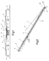
- Number 1 in Figure 1 indicates a vehicle fitted with a spreader unit S for transporting and spreading deicer fluid on a pavement.
- Deicer fluid may vary in viscosity, depending on its composition, and is contained in a tank on spreader unit S.
- Spreader unit S also comprises two supporting arms 2, 3; a number of spreader assemblies 4 connected directly to supporting arms 2, 3 and optionally to a rigid structure of spreader unit S; and a pump (not shown) for pumping the deicer fluid to the spreader assemblies.
- Each spreader assembly 4 preferably comprises a bladed rotary disk onto which the deicer fluid is fed; and the rotary disk blades spread the deicer fluid centrifugally over a work area diverging from the rotary disk.
- Each supporting arm 2, 3 is hinged about a vertical axis A to the rigid structure of spreader unit S, and is sustained substantially perpendicular to axis A by respective ties 5 adjustable manually in length and fixed to the rigid structure.
- Arms 2, 3 are movable by linear actuators 6 between a work position ( Figure 1 ), and a rest position in which they are substantially parallel to the sides of vehicle 1.
- Each arm 2, 3 comprises a high-pressure hydraulic line 11 for transferring mechanical power, and a low-pressure fluid line 12 for transporting the deicer fluid.
- Each arm 2, 3 has a hollow, preferably closed section, and lines 11, 12 are housed inside relative arm 2, 3 for shock protection.
- Each arm 2, 3 ( Figure 2 ) comprises a tubular casing 7 connected directly to respective tie 5; and a sliding member 8 movable telescopically inside tubular casing 7.
- Each arm 2, 3 also comprises a linear actuator L connected between tubular casing 7 and sliding member 8 to control the telescopic movement of sliding member 8 between an extracted position ( Figure 1 ) and a withdrawn position ( Figure 2 ).
- Tubular casing 7 has a rectangular cross section, and comprises an end portion 9 defining axis A as described in detail below; and an end portion 10 axially opposite end portion 9 and defining an opening for extraction of sliding member 8.
- Tubular casing 7 is designed to directly support a spreader assembly 4, and lines 11 and 12 have respective ports P1, P2 (shown schematically) connected to a relative spreader assembly 4 to respectively drive the rotary spreader disk by means of a rotary hydraulic motor on spreader assembly 4, and to feed the deicer fluid to the bladed disk.
- Lines 11, 12 also have a second group of ports connected parallel to ports P1, P2 and located on a free end portion 13 of sliding member 8, as described in more detail below.
- line 11 comprises a feed pipe 14 and a drain pipe 15 for controlling the hydraulic motors of spreader assemblies 4 connected to supporting arm 2, 3.
- Feed pipe 14 and drain pipe 15 have an inlet port 16 and outlet port 17 respectively, and inlet port 16 is connected to a hydraulic pump of spreader unit S.
- Line 12 comprises a telescopic pipe T, preferably the same as pipes 14, 15, and is supplied through an inlet port 18 by the deicer fluid pump of spreader unit S.
- Ports 16, 17, 18 define a third group of ports of lines 11, 12, and are located on end portion 9, which also supports a pin 19 connected rigidly to the rigid structure of spreader unit S and rotating with respect to tubular casing 7 by means of two bearings to define axis A.
- Figure 4 shows the free end portion 13 of sliding member 8, and in particular an outlet port 20 of feed pipe 14, an inlet port 21 of drain pipe 15, and an outlet port 22 of line 12, which ports define the second group of ports of lines 11, 12.
- a spreader assembly 4 is connected mechanically to free end portion 13 by a plate, and ports 20, 21, 22 are connected to spreader assembly 4 by respective hoses (not shown).
- pipes 14, 15 and line 12 are rigid and telescopic.
- each pipe 14, 15, T has a circular cross section, and comprises a sleeve 23 connected rigidly to tubular casing 7 and defining inlet port 16 and outlet port 17 respectively.
- Each pipe 14, 15, T also comprises a sliding member 24 movable in fluidtight manner inside sleeve 23.
- Sliding member 24 of each pipe 14, 15, T comprises an end portion connected to an elbow joint 25, which defines outlet port 20 or inlet portion 21, and is connected rigidly to free end portion 13.
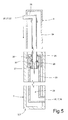
- Figure 5 shows a section of a preferred embodiment of pipes 14, 15, T.
- Sleeve 23 comprises a dynamic seal 26 which cooperates with the outer surface of sliding member 24 to ensure adequate fluidtight sealing.
- Sliding member 24 is connected to a second dynamic seal 27 located on the opposite axial side with respect to elbow joint 25, and which cooperates with the inner surface of sleeve 23 to guide sliding member 24 in a straight direction.
- Sliding member 24 defines a number of radial holes 28 located between dynamic seal 27 and dynamic seal 26 to connect a chamber 29, defined inside sleeve 23, between ports 16, 17, 18 and dynamic seal 27, to a chamber 30 defined inside sleeve 23, between dynamic seal 26 and dynamic seal 27.
- Spreader unit S operates as follows.
- linear actuators L extract sliding members 24 by means of respective elbow joints 25.
- the hydraulic fluid powers the rotary motors connected to the bladed disks and circulates along pipes 14 and 15, while the deicer fluid flows to spreader assemblies 4 connected in parallel to one another by lines 11 and 12.
- vehicle 1 spreads the deicer fluid to a width substantially defined by the total ground width of the work areas of spreader assemblies 4.
- holes 28 allow hydraulic fluid flow between chamber 29 and chamber 30 to ensure rapid movement of sliding member 24.
- Spreader unit S according to the present invention has the following advantages.
- the telescopic design of fluid lines 11, 12 and of the structural part comprising tubular casing 7 and sliding member 8 enables a number of spreader assemblies 4 to be supported in a compact configuration that is easy to produce and maintain.
- An industrial vehicle with compact lateral arms can be certified for on-road travel, unlike vehicles with bulky arms, that are too wide and are only allowed to circulate within the airport.
- Telescopic arms are extremely lightweight, and can be maintained in the projecting extracted position by means of simple connecting devices.
- Holes 28 provide for faster movement of sliding member 8.
- lines 11, 12 may be multistage lines and comprise a number of telescopic sliding members.
- holes 28 are designed to connect chambers 29, 30 as the telescopic members are withdrawn, to speed up operation of arms 2, 3.
- Spreader unit S may be either integrated in or removable from vehicle 1. In which latter case, a heavyduty vehicle may be adapted to spread pavements with deicer fluid.
- each spreader assembly 4 may comprise a nozzle bar connected to low-pressure line 12 instead of the hydraulic motor powered bladed disk, and which comprises a number of nozzles for spraying the deicer fluid.
- Each nozzle bar is connected by an articulated mechanism to relative arm 2, 3. More specifically, arms 2, 3 have a fixed vertical position, and the articulated mechanism is operated, e.g. by a hydraulic linear actuator, to regulate the distance between the nozzle bar and the pavement. At least in use, the nozzle bar is normally parallel to the pavement.
Landscapes
- Life Sciences & Earth Sciences (AREA)
- Engineering & Computer Science (AREA)
- Insects & Arthropods (AREA)
- Pest Control & Pesticides (AREA)
- Wood Science & Technology (AREA)
- Zoology (AREA)
- Environmental Sciences (AREA)
- Architecture (AREA)
- Civil Engineering (AREA)
- Structural Engineering (AREA)
- Road Paving Machines (AREA)
- Fittings On The Vehicle Exterior For Carrying Loads, And Devices For Holding Or Mounting Articles (AREA)
- Stringed Musical Instruments (AREA)
- Hooks, Suction Cups, And Attachment By Adhesive Means (AREA)
Abstract
Description
- The present invention relates to a spreader unit fitted to an industrial vehicle and having a supporting arm for deicer spreader assemblies, e.g. for spreading airport pavements with deicer fluid.
- Airport pavements normally comprise the runways, taxiways, and the terminal area, and cover an extensive area that must be spread with deicer fluid as fast as possible to avoid delays in air traffic departures and arrivals.
- It is an object of the present invention to provide a spreader unit having a supporting arm for spreader assemblies, and designed to spread deicer fluid effectively and rapidly over extensive areas.
- According to the present invention, there is provided a spreader unit with a supporting arm as claimed in Claim 1.
- A preferred, non-limiting embodiment of the present invention will be described by way of example with reference to the accompanying drawings, in which:
-
Figure 1 shows a rear view of a spreader vehicle comprising two supporting arms in accordance with the present invention; -
Figure 2 shows a view in perspective of a supporting arm in accordance with the present invention; -
Figures 3 and 4 show partial views in perspective of respective end portions of theFigure 2 supporting arm; -
Figure 5 shows a schematic section of a detail of theFigure 1 supporting arms. - Number 1 in
Figure 1 indicates a vehicle fitted with a spreader unit S for transporting and spreading deicer fluid on a pavement. Deicer fluid may vary in viscosity, depending on its composition, and is contained in a tank on spreader unit S. - Spreader unit S also comprises two supporting
arms spreader assemblies 4 connected directly to supportingarms - Each
spreader assembly 4 preferably comprises a bladed rotary disk onto which the deicer fluid is fed; and the rotary disk blades spread the deicer fluid centrifugally over a work area diverging from the rotary disk. - Each supporting
arm respective ties 5 adjustable manually in length and fixed to the rigid structure. -
Arms linear actuators 6 between a work position (Figure 1 ), and a rest position in which they are substantially parallel to the sides of vehicle 1. - Each
arm hydraulic line 11 for transferring mechanical power, and a low-pressure fluid line 12 for transporting the deicer fluid. Eacharm lines relative arm - Each
arm 2, 3 (Figure 2 ) comprises atubular casing 7 connected directly torespective tie 5; and a slidingmember 8 movable telescopically insidetubular casing 7. - Each
arm tubular casing 7 and slidingmember 8 to control the telescopic movement of slidingmember 8 between an extracted position (Figure 1 ) and a withdrawn position (Figure 2 ). -
Tubular casing 7 has a rectangular cross section, and comprises anend portion 9 defining axis A as described in detail below; and anend portion 10 axiallyopposite end portion 9 and defining an opening for extraction of slidingmember 8. -
Tubular casing 7 is designed to directly support aspreader assembly 4, andlines relative spreader assembly 4 to respectively drive the rotary spreader disk by means of a rotary hydraulic motor onspreader assembly 4, and to feed the deicer fluid to the bladed disk. -
Lines free end portion 13 of slidingmember 8, as described in more detail below. - More specifically (
Figure 3 ),line 11 comprises afeed pipe 14 and adrain pipe 15 for controlling the hydraulic motors ofspreader assemblies 4 connected to supportingarm pipe 14 anddrain pipe 15 have aninlet port 16 andoutlet port 17 respectively, andinlet port 16 is connected to a hydraulic pump of spreader unit S. -
Line 12 comprises a telescopic pipe T, preferably the same aspipes inlet port 18 by the deicer fluid pump of spreader unit S. -
Ports lines end portion 9, which also supports apin 19 connected rigidly to the rigid structure of spreader unit S and rotating with respect totubular casing 7 by means of two bearings to define axis A. -
Figure 4 shows thefree end portion 13 of slidingmember 8, and in particular anoutlet port 20 offeed pipe 14, aninlet port 21 ofdrain pipe 15, and anoutlet port 22 ofline 12, which ports define the second group of ports oflines - A
spreader assembly 4 is connected mechanically tofree end portion 13 by a plate, andports spreader assembly 4 by respective hoses (not shown). - To allow movement of sliding
member 8,pipes line 12 are rigid and telescopic. - More specifically, each
pipe sleeve 23 connected rigidly totubular casing 7 and defininginlet port 16 andoutlet port 17 respectively. - Each
pipe member 24 movable in fluidtight manner insidesleeve 23. - Sliding
member 24 of eachpipe elbow joint 25, which definesoutlet port 20 orinlet portion 21, and is connected rigidly tofree end portion 13. -
Figure 5 shows a section of a preferred embodiment ofpipes -
Sleeve 23 comprises adynamic seal 26 which cooperates with the outer surface of slidingmember 24 to ensure adequate fluidtight sealing. -
Sliding member 24 is connected to a seconddynamic seal 27 located on the opposite axial side with respect toelbow joint 25, and which cooperates with the inner surface ofsleeve 23 to guide slidingmember 24 in a straight direction. - Sliding
member 24 defines a number ofradial holes 28 located betweendynamic seal 27 anddynamic seal 26 to connect achamber 29, defined insidesleeve 23, betweenports dynamic seal 27, to achamber 30 defined insidesleeve 23, betweendynamic seal 26 anddynamic seal 27. - Spreader unit S operates as follows.
- When spreader assemblies 4 of vehicle 1 are off, e.g. when vehicle 1 is parked,
arms linear actuators 6, and vehicle 1 occupies substantially the same space as a normal spreader vehicle. - When
spreader assemblies 4 are to be turned on,arms linear actuators 6, and slidingmembers 8 are extracted by linear actuators L (Figure 1 ). - As sliding
members 8 are extracted, linear actuators Lextract sliding members 24 by means ofrespective elbow joints 25. The hydraulic fluid powers the rotary motors connected to the bladed disks and circulates alongpipes spreader assemblies 4 connected in parallel to one another bylines - In this position, vehicle 1 spreads the deicer fluid to a width substantially defined by the total ground width of the work areas of
spreader assemblies 4. - When
arms holes 28 allow hydraulic fluid flow betweenchamber 29 andchamber 30 to ensure rapid movement of slidingmember 24. - Spreader unit S according to the present invention has the following advantages.
- The telescopic design of
fluid lines tubular casing 7 and slidingmember 8 enables a number ofspreader assemblies 4 to be supported in a compact configuration that is easy to produce and maintain. - An industrial vehicle with compact lateral arms can be certified for on-road travel, unlike vehicles with bulky arms, that are too wide and are only allowed to circulate within the airport.
- Telescopic arms are extremely lightweight, and can be maintained in the projecting extracted position by means of simple connecting devices.
- As a result of the reduction in weight, more deicer fluid can be carried in the tank of spreader unit S.
-
Holes 28 provide for faster movement of slidingmember 8. - Clearly, changes may be made to spreader unit S as described and illustrated herein without, however, departing from the protective scope of the present invention as defined in the accompanying Claims.
- More specifically,
lines holes 28 are designed to connectchambers arms - Spreader unit S may be either integrated in or removable from vehicle 1. In which latter case, a heavyduty vehicle may be adapted to spread pavements with deicer fluid.
- Alternatively, each
spreader assembly 4 may comprise a nozzle bar connected to low-pressure line 12 instead of the hydraulic motor powered bladed disk, and which comprises a number of nozzles for spraying the deicer fluid. - Each nozzle bar is connected by an articulated mechanism to
relative arm arms
Claims (11)
- A spreader unit (S) for spreading deicer on a pavement, and comprising at least one supporting arm (2; 3) having a casing (7) connected to a rigid structure of said spreader unit (S), a first sliding member (8) connected telescopically to said casing (7), and at least one telescopic pipe (T) for said deicer and defining a connecting port (22) connectable to a spreader assembly (4) for spreading said deicer.
- A spreader unit as claimed in Claim 1, characterized in that said telescopic pipe (T) comprises a sleeve (23); and a second sliding member (24) extractable from said sleeve (23) by means of said first sliding member (8) and defining a pipe connected to said connecting port (22).
- A spreader unit as claimed in Claim 2, characterized in that said second sliding member (24) is connected to said first sliding member (8) by a fluidic joint (25) defining said connecting port (22).
- A spreader unit as claimed in any one of the foregoing Claims, characterized in that said telescopic pipe (T) comprises first sealing means (26) fixed with respect to said sleeve (23) and cooperating with said second sliding member (24); second sealing means (27) fixed with respect to said second sliding member (24) and cooperating with said sleeve (23); an inlet port (18) defined by said sleeve (23); and fluidic connecting means (28) for connecting a first chamber (29), defined between said second sealing means (27) and said inlet port (18), to a second chamber (30) defined between said first and second sealing means (26, 27).
- A spreader unit as claimed in any one of the foregoing Claims, characterized in that said at least one supporting arm (2; 3) has a hollow cross section; and said telescopic pipe (T) is at least partly housed inside said at least one supporting arm (2; 3).
- A spreader unit as claimed in any one of the foregoing Claims, characterized by comprising a linear actuator (L) connected between said first sliding member (8) and said casing (7) to extract said first sliding member (8).
- A spreader unit as claimed in any one of the foregoing Claims, characterized in that said at least one supporting arm (2; 3) is hinged to a rigid structure of said spreader unit (S); and by comprising a tie (5) connected between said supporting arm (2; 3) and said rigid structure.
- A spreader unit as claimed in any one of the foregoing Claims, characterized by comprising at least a second and a third telescopic pipe (14, 15) connectable by respective ports (20, 21) to a spreader assembly (4) comprising a hydraulic user device.
- A spreader unit as claimed in any one of Claims 1 to 7, characterized in that said spreader assembly comprises a nozzle bar connectable to said connecting port (22).
- A spreader unit as claimed in any one of the foregoing Claims, characterized by comprising a tank for said deicer fluid; and a pump connecting said tank to said connecting port (22).
- A vehicle comprising a spreader unit (S) as claimed in any one of the foregoing Claims; and at least one spreader assembly (4) connected to said at least one supporting arm (2; 3) and to said telescopic pipe (T).
Applications Claiming Priority (1)
| Application Number | Priority Date | Filing Date | Title |
|---|---|---|---|
| IT000409A ITTO20070409A1 (en) | 2007-06-08 | 2007-06-08 | SPILL-OUT UNIT WITH A SUPPORT ARM FOR SPARKLING GROUPS OF AN ANTI-ICE SUBSTANCE. |
Publications (2)
| Publication Number | Publication Date |
|---|---|
| EP2000595A1 true EP2000595A1 (en) | 2008-12-10 |
| EP2000595B1 EP2000595B1 (en) | 2017-02-01 |
Family
ID=39739901
Family Applications (1)
| Application Number | Title | Priority Date | Filing Date |
|---|---|---|---|
| EP08157823.9A Ceased EP2000595B1 (en) | 2007-06-08 | 2008-06-09 | Spreader unit with a supporting arm for deicer spreader assemblies |
Country Status (4)
| Country | Link |
|---|---|
| US (1) | US8308080B2 (en) |
| EP (1) | EP2000595B1 (en) |
| CA (1) | CA2634435A1 (en) |
| IT (1) | ITTO20070409A1 (en) |
Families Citing this family (5)
| Publication number | Priority date | Publication date | Assignee | Title |
|---|---|---|---|---|
| US8790736B2 (en) | 2012-10-01 | 2014-07-29 | Frito-Lay North America, Inc. | Savory granola cluster snack food |
| JP6079690B2 (en) * | 2014-04-18 | 2017-02-15 | 井関農機株式会社 | Chemical spraying work vehicle |
| JP6090416B2 (en) * | 2015-11-30 | 2017-03-08 | 井関農機株式会社 | Chemical spraying work vehicle |
| CN112252263A (en) * | 2020-12-10 | 2021-01-22 | 鞍山森远路桥股份有限公司 | Foldable spreading arm of deicing fluid spraying vehicle for airport pavement |
| CN115500337B (en) * | 2022-10-14 | 2023-07-07 | 九江市农业科学院 | Corn and soybean intercropping pesticide spraying device |
Citations (4)
| Publication number | Priority date | Publication date | Assignee | Title |
|---|---|---|---|---|
| US2331373A (en) * | 1940-11-22 | 1943-10-12 | Fisher & Ludlow Ltd | Liquid discharge appliance |
| EP0118366A1 (en) * | 1983-03-03 | 1984-09-12 | Seguip | Agricultural spraying boom |
| DE19749674A1 (en) * | 1997-11-10 | 1999-05-12 | Rudolf Winter | Spraying unit, especially for delivery of deicing fluid onto road or runway |
| WO2002072275A1 (en) * | 2001-03-14 | 2002-09-19 | Beggs Robert D | Boom sprayer and method of spraying |
Family Cites Families (11)
| Publication number | Priority date | Publication date | Assignee | Title |
|---|---|---|---|---|
| US1360382A (en) * | 1920-03-19 | 1920-11-30 | Arthur Sparrow | Barber's and hair-dresser's shampco and hair-washing device |
| US2064278A (en) * | 1933-10-17 | 1936-12-15 | Tappe Wilhelm | Apparatus for extinguishing fires |
| US2695307A (en) * | 1947-09-20 | 1954-11-23 | Union Chimique Belge Sa | Process of manufacturing polymerized organic silicon compounds |
| US2965307A (en) * | 1957-04-10 | 1960-12-20 | Ray F High | Extensible spraying apparatus |
| US3266728A (en) * | 1964-01-28 | 1966-08-16 | Hypro Inc | Control and by-pass valve unit for area spray system |
| US3897263A (en) * | 1973-11-02 | 1975-07-29 | Oliver Thurston Davis | Apparatus for washing and disinfecting trailer or van interiors |
| BG27569A1 (en) * | 1978-10-30 | 1979-12-12 | Georgiev | Telescopic sinking hydrant |
| US4805653A (en) * | 1985-09-09 | 1989-02-21 | Serv-Tech, Inc. | Mobile articulatable tube bundle cleaner |
| US5799835A (en) * | 1995-10-16 | 1998-09-01 | Gobbel; Keith | Sprayer extension device |
| US6085993A (en) * | 1998-09-15 | 2000-07-11 | Beggs; Robert D. | Boom sprayer and method of spraying |
| US7152811B2 (en) * | 2004-12-22 | 2006-12-26 | Cnh America Llc | Hydraulic boom stabilization device |
-
2007
- 2007-06-08 IT IT000409A patent/ITTO20070409A1/en unknown
-
2008
- 2008-06-06 CA CA002634435A patent/CA2634435A1/en not_active Abandoned
- 2008-06-07 US US12/135,171 patent/US8308080B2/en active Active
- 2008-06-09 EP EP08157823.9A patent/EP2000595B1/en not_active Ceased
Patent Citations (4)
| Publication number | Priority date | Publication date | Assignee | Title |
|---|---|---|---|---|
| US2331373A (en) * | 1940-11-22 | 1943-10-12 | Fisher & Ludlow Ltd | Liquid discharge appliance |
| EP0118366A1 (en) * | 1983-03-03 | 1984-09-12 | Seguip | Agricultural spraying boom |
| DE19749674A1 (en) * | 1997-11-10 | 1999-05-12 | Rudolf Winter | Spraying unit, especially for delivery of deicing fluid onto road or runway |
| WO2002072275A1 (en) * | 2001-03-14 | 2002-09-19 | Beggs Robert D | Boom sprayer and method of spraying |
Also Published As
| Publication number | Publication date |
|---|---|
| CA2634435A1 (en) | 2008-12-08 |
| EP2000595B1 (en) | 2017-02-01 |
| ITTO20070409A1 (en) | 2008-12-09 |
| US8308080B2 (en) | 2012-11-13 |
| US20090014563A1 (en) | 2009-01-15 |
Similar Documents
| Publication | Publication Date | Title |
|---|---|---|
| EP2000595B1 (en) | Spreader unit with a supporting arm for deicer spreader assemblies | |
| US3879789A (en) | Scrubbing machine | |
| EP1726777B1 (en) | System and method for suppressing dust and odors | |
| US3702488A (en) | Scrubbing machine | |
| CA1098454A (en) | Lifting equipment having telescopic boom with automatic extension limiting | |
| ES2684226T3 (en) | Electrohydraulically operated spray guns | |
| US20180086008A1 (en) | Concrete delivery system | |
| US20120255585A1 (en) | Portable System for Directing Pressurized Air Upon a Surface | |
| US3837029A (en) | Scrubbing machine | |
| US5765963A (en) | Pavement maintenance vehicle | |
| MX2010012095A (en) | Conduit cleaning apparatus. | |
| WO2012059868A1 (en) | Apparatus for spraying liquid substances, such as paints or water, on the inner walls of tunnels | |
| CA2731731A1 (en) | Vacuum-operated material transfer system and method | |
| CN106391600A (en) | Conveying pipe cleaning device | |
| US11111643B2 (en) | Bi-directional snow removal machine | |
| CN108556808A (en) | A kind of washing and disinfection car | |
| KR102054027B1 (en) | Mobile concrete pump and method for using it in the transport state | |
| DE102015100439B3 (en) | Easy to maintain telescopic swivel arm and working or operating procedures | |
| CN112293387A (en) | An electronically controlled multifunctional medicine spraying device | |
| US6299257B1 (en) | Machine for removing tile with articulated frame | |
| EP2920371B1 (en) | Device for cleaning surfaces | |
| CN113665463A (en) | Drainage emergency vehicle | |
| CN105408548A (en) | Snow clearing device | |
| CN217231616U (en) | Drainage and water absorption vehicle | |
| EP3195938B1 (en) | Module for covering sections requiring protection or elements on fixed surfaces |
Legal Events
| Date | Code | Title | Description |
|---|---|---|---|
| PUAI | Public reference made under article 153(3) epc to a published international application that has entered the european phase |
Free format text: ORIGINAL CODE: 0009012 |
|
| AK | Designated contracting states |
Kind code of ref document: A1 Designated state(s): AT BE BG CH CY CZ DE DK EE ES FI FR GB GR HR HU IE IS IT LI LT LU LV MC MT NL NO PL PT RO SE SI SK TR |
|
| AX | Request for extension of the european patent |
Extension state: AL BA MK RS |
|
| 17P | Request for examination filed |
Effective date: 20090610 |
|
| 17Q | First examination report despatched |
Effective date: 20090709 |
|
| AKX | Designation fees paid |
Designated state(s): DE FR IT |
|
| GRAP | Despatch of communication of intention to grant a patent |
Free format text: ORIGINAL CODE: EPIDOSNIGR1 |
|
| INTG | Intention to grant announced |
Effective date: 20160912 |
|
| GRAS | Grant fee paid |
Free format text: ORIGINAL CODE: EPIDOSNIGR3 |
|
| GRAA | (expected) grant |
Free format text: ORIGINAL CODE: 0009210 |
|
| AK | Designated contracting states |
Kind code of ref document: B1 Designated state(s): DE FR IT |
|
| REG | Reference to a national code |
Ref country code: DE Ref legal event code: R096 Ref document number: 602008048642 Country of ref document: DE |
|
| REG | Reference to a national code |
Ref country code: FR Ref legal event code: PLFP Year of fee payment: 10 |
|
| PG25 | Lapsed in a contracting state [announced via postgrant information from national office to epo] |
Ref country code: IT Free format text: LAPSE BECAUSE OF FAILURE TO SUBMIT A TRANSLATION OF THE DESCRIPTION OR TO PAY THE FEE WITHIN THE PRESCRIBED TIME-LIMIT Effective date: 20170201 |
|
| REG | Reference to a national code |
Ref country code: DE Ref legal event code: R097 Ref document number: 602008048642 Country of ref document: DE |
|
| PLBE | No opposition filed within time limit |
Free format text: ORIGINAL CODE: 0009261 |
|
| STAA | Information on the status of an ep patent application or granted ep patent |
Free format text: STATUS: NO OPPOSITION FILED WITHIN TIME LIMIT |
|
| REG | Reference to a national code |
Ref country code: DE Ref legal event code: R119 Ref document number: 602008048642 Country of ref document: DE |
|
| 26N | No opposition filed |
Effective date: 20171103 |
|
| PG25 | Lapsed in a contracting state [announced via postgrant information from national office to epo] |
Ref country code: DE Free format text: LAPSE BECAUSE OF NON-PAYMENT OF DUE FEES Effective date: 20180103 |
|
| REG | Reference to a national code |
Ref country code: FR Ref legal event code: PLFP Year of fee payment: 11 |
|
| PGFP | Annual fee paid to national office [announced via postgrant information from national office to epo] |
Ref country code: FR Payment date: 20200626 Year of fee payment: 13 |
|
| PG25 | Lapsed in a contracting state [announced via postgrant information from national office to epo] |
Ref country code: FR Free format text: LAPSE BECAUSE OF NON-PAYMENT OF DUE FEES Effective date: 20210630 |