EP2000659A2 - Intake system - Google Patents
Intake system Download PDFInfo
- Publication number
- EP2000659A2 EP2000659A2 EP20080104049 EP08104049A EP2000659A2 EP 2000659 A2 EP2000659 A2 EP 2000659A2 EP 20080104049 EP20080104049 EP 20080104049 EP 08104049 A EP08104049 A EP 08104049A EP 2000659 A2 EP2000659 A2 EP 2000659A2
- Authority
- EP
- European Patent Office
- Prior art keywords
- weld
- edge
- intake system
- welding
- parts
- Prior art date
- Legal status (The legal status is an assumption and is not a legal conclusion. Google has not performed a legal analysis and makes no representation as to the accuracy of the status listed.)
- Granted
Links
- 238000003466 welding Methods 0.000 claims abstract description 34
- 238000002485 combustion reaction Methods 0.000 claims abstract description 6
- 239000012815 thermoplastic material Substances 0.000 claims abstract description 4
- 238000007599 discharging Methods 0.000 claims abstract 2
- 238000004519 manufacturing process Methods 0.000 claims description 2
- 230000015572 biosynthetic process Effects 0.000 claims 1
- 238000012216 screening Methods 0.000 claims 1
- 239000004033 plastic Substances 0.000 description 3
- 238000000034 method Methods 0.000 description 2
- 229920001169 thermoplastic Polymers 0.000 description 2
- 230000000007 visual effect Effects 0.000 description 2
- 241000237983 Trochidae Species 0.000 description 1
- 238000011109 contamination Methods 0.000 description 1
- 230000007613 environmental effect Effects 0.000 description 1
- 238000010438 heat treatment Methods 0.000 description 1
- 238000001746 injection moulding Methods 0.000 description 1
- 230000001788 irregular Effects 0.000 description 1
- 239000007788 liquid Substances 0.000 description 1
- 238000002844 melting Methods 0.000 description 1
- 230000008018 melting Effects 0.000 description 1
- 230000002093 peripheral effect Effects 0.000 description 1
- 239000004416 thermosoftening plastic Substances 0.000 description 1
Images
Classifications
-
- F—MECHANICAL ENGINEERING; LIGHTING; HEATING; WEAPONS; BLASTING
- F02—COMBUSTION ENGINES; HOT-GAS OR COMBUSTION-PRODUCT ENGINE PLANTS
- F02M—SUPPLYING COMBUSTION ENGINES IN GENERAL WITH COMBUSTIBLE MIXTURES OR CONSTITUENTS THEREOF
- F02M35/00—Combustion-air cleaners, air intakes, intake silencers, or induction systems specially adapted for, or arranged on, internal-combustion engines
- F02M35/10—Air intakes; Induction systems
- F02M35/1034—Manufacturing and assembling intake systems
- F02M35/10354—Joining multiple sections together
- F02M35/1036—Joining multiple sections together by welding, bonding or the like
-
- B—PERFORMING OPERATIONS; TRANSPORTING
- B29—WORKING OF PLASTICS; WORKING OF SUBSTANCES IN A PLASTIC STATE IN GENERAL
- B29C—SHAPING OR JOINING OF PLASTICS; SHAPING OF MATERIAL IN A PLASTIC STATE, NOT OTHERWISE PROVIDED FOR; AFTER-TREATMENT OF THE SHAPED PRODUCTS, e.g. REPAIRING
- B29C65/00—Joining or sealing of preformed parts, e.g. welding of plastics materials; Apparatus therefor
- B29C65/02—Joining or sealing of preformed parts, e.g. welding of plastics materials; Apparatus therefor by heating, with or without pressure
- B29C65/06—Joining or sealing of preformed parts, e.g. welding of plastics materials; Apparatus therefor by heating, with or without pressure using friction, e.g. spin welding
- B29C65/0609—Joining or sealing of preformed parts, e.g. welding of plastics materials; Apparatus therefor by heating, with or without pressure using friction, e.g. spin welding characterised by the movement of the parts to be joined
- B29C65/0618—Linear
-
- B—PERFORMING OPERATIONS; TRANSPORTING
- B29—WORKING OF PLASTICS; WORKING OF SUBSTANCES IN A PLASTIC STATE IN GENERAL
- B29C—SHAPING OR JOINING OF PLASTICS; SHAPING OF MATERIAL IN A PLASTIC STATE, NOT OTHERWISE PROVIDED FOR; AFTER-TREATMENT OF THE SHAPED PRODUCTS, e.g. REPAIRING
- B29C65/00—Joining or sealing of preformed parts, e.g. welding of plastics materials; Apparatus therefor
- B29C65/02—Joining or sealing of preformed parts, e.g. welding of plastics materials; Apparatus therefor by heating, with or without pressure
- B29C65/06—Joining or sealing of preformed parts, e.g. welding of plastics materials; Apparatus therefor by heating, with or without pressure using friction, e.g. spin welding
- B29C65/069—Joining or sealing of preformed parts, e.g. welding of plastics materials; Apparatus therefor by heating, with or without pressure using friction, e.g. spin welding the welding tool cooperating with specially formed features of at least one of the parts to be joined, e.g. cooperating with holes or ribs of at least one of the parts to be joined
-
- B—PERFORMING OPERATIONS; TRANSPORTING
- B29—WORKING OF PLASTICS; WORKING OF SUBSTANCES IN A PLASTIC STATE IN GENERAL
- B29C—SHAPING OR JOINING OF PLASTICS; SHAPING OF MATERIAL IN A PLASTIC STATE, NOT OTHERWISE PROVIDED FOR; AFTER-TREATMENT OF THE SHAPED PRODUCTS, e.g. REPAIRING
- B29C65/00—Joining or sealing of preformed parts, e.g. welding of plastics materials; Apparatus therefor
- B29C65/78—Means for handling the parts to be joined, e.g. for making containers or hollow articles, e.g. means for handling sheets, plates, web-like materials, tubular articles, hollow articles or elements to be joined therewith; Means for discharging the joined articles from the joining apparatus
- B29C65/7841—Holding or clamping means for handling purposes
-
- B—PERFORMING OPERATIONS; TRANSPORTING
- B29—WORKING OF PLASTICS; WORKING OF SUBSTANCES IN A PLASTIC STATE IN GENERAL
- B29C—SHAPING OR JOINING OF PLASTICS; SHAPING OF MATERIAL IN A PLASTIC STATE, NOT OTHERWISE PROVIDED FOR; AFTER-TREATMENT OF THE SHAPED PRODUCTS, e.g. REPAIRING
- B29C66/00—General aspects of processes or apparatus for joining preformed parts
- B29C66/01—General aspects dealing with the joint area or with the area to be joined
- B29C66/05—Particular design of joint configurations
- B29C66/10—Particular design of joint configurations particular design of the joint cross-sections
- B29C66/13—Single flanged joints; Fin-type joints; Single hem joints; Edge joints; Interpenetrating fingered joints; Other specific particular designs of joint cross-sections not provided for in groups B29C66/11 - B29C66/12
- B29C66/131—Single flanged joints, i.e. one of the parts to be joined being rigid and flanged in the joint area
- B29C66/1312—Single flange to flange joints, the parts to be joined being rigid
-
- B—PERFORMING OPERATIONS; TRANSPORTING
- B29—WORKING OF PLASTICS; WORKING OF SUBSTANCES IN A PLASTIC STATE IN GENERAL
- B29C—SHAPING OR JOINING OF PLASTICS; SHAPING OF MATERIAL IN A PLASTIC STATE, NOT OTHERWISE PROVIDED FOR; AFTER-TREATMENT OF THE SHAPED PRODUCTS, e.g. REPAIRING
- B29C66/00—General aspects of processes or apparatus for joining preformed parts
- B29C66/01—General aspects dealing with the joint area or with the area to be joined
- B29C66/32—Measures for keeping the burr form under control; Avoiding burr formation; Shaping the burr
- B29C66/322—Providing cavities in the joined article to collect the burr
-
- B—PERFORMING OPERATIONS; TRANSPORTING
- B29—WORKING OF PLASTICS; WORKING OF SUBSTANCES IN A PLASTIC STATE IN GENERAL
- B29C—SHAPING OR JOINING OF PLASTICS; SHAPING OF MATERIAL IN A PLASTIC STATE, NOT OTHERWISE PROVIDED FOR; AFTER-TREATMENT OF THE SHAPED PRODUCTS, e.g. REPAIRING
- B29C66/00—General aspects of processes or apparatus for joining preformed parts
- B29C66/50—General aspects of joining tubular articles; General aspects of joining long products, i.e. bars or profiled elements; General aspects of joining single elements to tubular articles, hollow articles or bars; General aspects of joining several hollow-preforms to form hollow or tubular articles
- B29C66/51—Joining tubular articles, profiled elements or bars; Joining single elements to tubular articles, hollow articles or bars; Joining several hollow-preforms to form hollow or tubular articles
- B29C66/53—Joining single elements to tubular articles, hollow articles or bars
- B29C66/534—Joining single elements to open ends of tubular or hollow articles or to the ends of bars
- B29C66/5344—Joining single elements to open ends of tubular or hollow articles or to the ends of bars said single elements being substantially annular, i.e. of finite length, e.g. joining flanges to tube ends
-
- B—PERFORMING OPERATIONS; TRANSPORTING
- B29—WORKING OF PLASTICS; WORKING OF SUBSTANCES IN A PLASTIC STATE IN GENERAL
- B29C—SHAPING OR JOINING OF PLASTICS; SHAPING OF MATERIAL IN A PLASTIC STATE, NOT OTHERWISE PROVIDED FOR; AFTER-TREATMENT OF THE SHAPED PRODUCTS, e.g. REPAIRING
- B29C66/00—General aspects of processes or apparatus for joining preformed parts
- B29C66/50—General aspects of joining tubular articles; General aspects of joining long products, i.e. bars or profiled elements; General aspects of joining single elements to tubular articles, hollow articles or bars; General aspects of joining several hollow-preforms to form hollow or tubular articles
- B29C66/51—Joining tubular articles, profiled elements or bars; Joining single elements to tubular articles, hollow articles or bars; Joining several hollow-preforms to form hollow or tubular articles
- B29C66/54—Joining several hollow-preforms, e.g. half-shells, to form hollow articles, e.g. for making balls, containers; Joining several hollow-preforms, e.g. half-cylinders, to form tubular articles
-
- B—PERFORMING OPERATIONS; TRANSPORTING
- B29—WORKING OF PLASTICS; WORKING OF SUBSTANCES IN A PLASTIC STATE IN GENERAL
- B29C—SHAPING OR JOINING OF PLASTICS; SHAPING OF MATERIAL IN A PLASTIC STATE, NOT OTHERWISE PROVIDED FOR; AFTER-TREATMENT OF THE SHAPED PRODUCTS, e.g. REPAIRING
- B29C66/00—General aspects of processes or apparatus for joining preformed parts
- B29C66/50—General aspects of joining tubular articles; General aspects of joining long products, i.e. bars or profiled elements; General aspects of joining single elements to tubular articles, hollow articles or bars; General aspects of joining several hollow-preforms to form hollow or tubular articles
- B29C66/51—Joining tubular articles, profiled elements or bars; Joining single elements to tubular articles, hollow articles or bars; Joining several hollow-preforms to form hollow or tubular articles
- B29C66/54—Joining several hollow-preforms, e.g. half-shells, to form hollow articles, e.g. for making balls, containers; Joining several hollow-preforms, e.g. half-cylinders, to form tubular articles
- B29C66/542—Joining several hollow-preforms, e.g. half-shells, to form hollow articles, e.g. for making balls, containers; Joining several hollow-preforms, e.g. half-cylinders, to form tubular articles joining hollow covers or hollow bottoms to open ends of container bodies
-
- B—PERFORMING OPERATIONS; TRANSPORTING
- B29—WORKING OF PLASTICS; WORKING OF SUBSTANCES IN A PLASTIC STATE IN GENERAL
- B29C—SHAPING OR JOINING OF PLASTICS; SHAPING OF MATERIAL IN A PLASTIC STATE, NOT OTHERWISE PROVIDED FOR; AFTER-TREATMENT OF THE SHAPED PRODUCTS, e.g. REPAIRING
- B29C66/00—General aspects of processes or apparatus for joining preformed parts
- B29C66/80—General aspects of machine operations or constructions and parts thereof
- B29C66/81—General aspects of the pressing elements, i.e. the elements applying pressure on the parts to be joined in the area to be joined, e.g. the welding jaws or clamps
- B29C66/814—General aspects of the pressing elements, i.e. the elements applying pressure on the parts to be joined in the area to be joined, e.g. the welding jaws or clamps characterised by the design of the pressing elements, e.g. of the welding jaws or clamps
- B29C66/8141—General aspects of the pressing elements, i.e. the elements applying pressure on the parts to be joined in the area to be joined, e.g. the welding jaws or clamps characterised by the design of the pressing elements, e.g. of the welding jaws or clamps characterised by the surface geometry of the part of the pressing elements, e.g. welding jaws or clamps, coming into contact with the parts to be joined
- B29C66/81411—General aspects of the pressing elements, i.e. the elements applying pressure on the parts to be joined in the area to be joined, e.g. the welding jaws or clamps characterised by the design of the pressing elements, e.g. of the welding jaws or clamps characterised by the surface geometry of the part of the pressing elements, e.g. welding jaws or clamps, coming into contact with the parts to be joined characterised by its cross-section, e.g. transversal or longitudinal, being non-flat
- B29C66/81425—General aspects of the pressing elements, i.e. the elements applying pressure on the parts to be joined in the area to be joined, e.g. the welding jaws or clamps characterised by the design of the pressing elements, e.g. of the welding jaws or clamps characterised by the surface geometry of the part of the pressing elements, e.g. welding jaws or clamps, coming into contact with the parts to be joined characterised by its cross-section, e.g. transversal or longitudinal, being non-flat being stepped, e.g. comprising a shoulder
-
- B—PERFORMING OPERATIONS; TRANSPORTING
- B29—WORKING OF PLASTICS; WORKING OF SUBSTANCES IN A PLASTIC STATE IN GENERAL
- B29C—SHAPING OR JOINING OF PLASTICS; SHAPING OF MATERIAL IN A PLASTIC STATE, NOT OTHERWISE PROVIDED FOR; AFTER-TREATMENT OF THE SHAPED PRODUCTS, e.g. REPAIRING
- B29C66/00—General aspects of processes or apparatus for joining preformed parts
- B29C66/80—General aspects of machine operations or constructions and parts thereof
- B29C66/83—General aspects of machine operations or constructions and parts thereof characterised by the movement of the joining or pressing tools
- B29C66/832—Reciprocating joining or pressing tools
- B29C66/8322—Joining or pressing tools reciprocating along one axis
-
- F—MECHANICAL ENGINEERING; LIGHTING; HEATING; WEAPONS; BLASTING
- F02—COMBUSTION ENGINES; HOT-GAS OR COMBUSTION-PRODUCT ENGINE PLANTS
- F02M—SUPPLYING COMBUSTION ENGINES IN GENERAL WITH COMBUSTIBLE MIXTURES OR CONSTITUENTS THEREOF
- F02M35/00—Combustion-air cleaners, air intakes, intake silencers, or induction systems specially adapted for, or arranged on, internal-combustion engines
- F02M35/10—Air intakes; Induction systems
- F02M35/10091—Air intakes; Induction systems characterised by details of intake ducts: shapes; connections; arrangements
- F02M35/10144—Connections of intake ducts to each other or to another device
-
- F—MECHANICAL ENGINEERING; LIGHTING; HEATING; WEAPONS; BLASTING
- F02—COMBUSTION ENGINES; HOT-GAS OR COMBUSTION-PRODUCT ENGINE PLANTS
- F02M—SUPPLYING COMBUSTION ENGINES IN GENERAL WITH COMBUSTIBLE MIXTURES OR CONSTITUENTS THEREOF
- F02M35/00—Combustion-air cleaners, air intakes, intake silencers, or induction systems specially adapted for, or arranged on, internal-combustion engines
- F02M35/10—Air intakes; Induction systems
- F02M35/10314—Materials for intake systems
- F02M35/10321—Plastics; Composites; Rubbers
-
- B—PERFORMING OPERATIONS; TRANSPORTING
- B29—WORKING OF PLASTICS; WORKING OF SUBSTANCES IN A PLASTIC STATE IN GENERAL
- B29C—SHAPING OR JOINING OF PLASTICS; SHAPING OF MATERIAL IN A PLASTIC STATE, NOT OTHERWISE PROVIDED FOR; AFTER-TREATMENT OF THE SHAPED PRODUCTS, e.g. REPAIRING
- B29C65/00—Joining or sealing of preformed parts, e.g. welding of plastics materials; Apparatus therefor
- B29C65/78—Means for handling the parts to be joined, e.g. for making containers or hollow articles, e.g. means for handling sheets, plates, web-like materials, tubular articles, hollow articles or elements to be joined therewith; Means for discharging the joined articles from the joining apparatus
- B29C65/7841—Holding or clamping means for handling purposes
- B29C65/7844—Holding or clamping means for handling purposes cooperating with specially formed features of at least one of the parts to be joined, e.g. cooperating with holes or ribs of at least one of the parts to be joined
-
- B—PERFORMING OPERATIONS; TRANSPORTING
- B29—WORKING OF PLASTICS; WORKING OF SUBSTANCES IN A PLASTIC STATE IN GENERAL
- B29C—SHAPING OR JOINING OF PLASTICS; SHAPING OF MATERIAL IN A PLASTIC STATE, NOT OTHERWISE PROVIDED FOR; AFTER-TREATMENT OF THE SHAPED PRODUCTS, e.g. REPAIRING
- B29C66/00—General aspects of processes or apparatus for joining preformed parts
- B29C66/80—General aspects of machine operations or constructions and parts thereof
- B29C66/81—General aspects of the pressing elements, i.e. the elements applying pressure on the parts to be joined in the area to be joined, e.g. the welding jaws or clamps
- B29C66/814—General aspects of the pressing elements, i.e. the elements applying pressure on the parts to be joined in the area to be joined, e.g. the welding jaws or clamps characterised by the design of the pressing elements, e.g. of the welding jaws or clamps
- B29C66/8141—General aspects of the pressing elements, i.e. the elements applying pressure on the parts to be joined in the area to be joined, e.g. the welding jaws or clamps characterised by the design of the pressing elements, e.g. of the welding jaws or clamps characterised by the surface geometry of the part of the pressing elements, e.g. welding jaws or clamps, coming into contact with the parts to be joined
- B29C66/81411—General aspects of the pressing elements, i.e. the elements applying pressure on the parts to be joined in the area to be joined, e.g. the welding jaws or clamps characterised by the design of the pressing elements, e.g. of the welding jaws or clamps characterised by the surface geometry of the part of the pressing elements, e.g. welding jaws or clamps, coming into contact with the parts to be joined characterised by its cross-section, e.g. transversal or longitudinal, being non-flat
- B29C66/81421—General aspects of the pressing elements, i.e. the elements applying pressure on the parts to be joined in the area to be joined, e.g. the welding jaws or clamps characterised by the design of the pressing elements, e.g. of the welding jaws or clamps characterised by the surface geometry of the part of the pressing elements, e.g. welding jaws or clamps, coming into contact with the parts to be joined characterised by its cross-section, e.g. transversal or longitudinal, being non-flat being convex or concave
- B29C66/81422—General aspects of the pressing elements, i.e. the elements applying pressure on the parts to be joined in the area to be joined, e.g. the welding jaws or clamps characterised by the design of the pressing elements, e.g. of the welding jaws or clamps characterised by the surface geometry of the part of the pressing elements, e.g. welding jaws or clamps, coming into contact with the parts to be joined characterised by its cross-section, e.g. transversal or longitudinal, being non-flat being convex or concave being convex
-
- B—PERFORMING OPERATIONS; TRANSPORTING
- B29—WORKING OF PLASTICS; WORKING OF SUBSTANCES IN A PLASTIC STATE IN GENERAL
- B29K—INDEXING SCHEME ASSOCIATED WITH SUBCLASSES B29B, B29C OR B29D, RELATING TO MOULDING MATERIALS OR TO MATERIALS FOR MOULDS, REINFORCEMENTS, FILLERS OR PREFORMED PARTS, e.g. INSERTS
- B29K2101/00—Use of unspecified macromolecular compounds as moulding material
- B29K2101/12—Thermoplastic materials
Definitions
- the invention relates to an intake system of an internal combustion engine according to the preamble of independent claim 1.
- the invention has for its object to avoid the disadvantages and to provide an intake system, which on the one hand has a reliable, defined connection of several parts to each other and on the other hand is designed visually appealing.
- the essential advantage of the invention is that the weld that connects the two parts is not visible from the outside, since a shielding edge is provided, which extends over the weld, and produces a uniform visual impression.
- the second part refers to a covering edge extending over the shielding edge.
- the fishing edge or the contact surfaces in the region of the fishing edge may have interruptions.
- a method for producing an intake system provides to form two parts of thermoplastic material, which are welded together, wherein first the first part in a holding mold fixed and the second part is placed on the first part and excited by vibrations to achieve a weld. To stabilize the first part slides are arranged in the welding tool, which hold this first part from the outside.
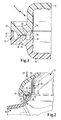
- FIG. 1 shows the detailed view of a lower shell 10 and an upper shell 12 of a suction system 11 shown here schematically.
- the two parts are joined together in the welding area 13 by friction welding.
- the lower shell 10 and the upper shell 12 are thermoplastic parts made by injection molding.
- the lower shell 10 has two circumferential catch edges 14, 15, which are supported on contact surfaces 16, 17 of the upper shell 12. Between the two catching edges 14, 15 is the circumferential weld at which the contact surface 19 with the contact surface 20 are welded together.
- the measure basis for the welding depth forms the fishing edge 14 with the contact surface 16, that is, that the welding process is continued until between catching edge 14 and contact surface 16, a smaller defined distance is set. Any existing welding discharge is collected in the two receiving grooves 21, 22 and is not visible from the outside. However, from the outside, the contact surface 17 and the fishing edge 15 can be seen. Possibly. Irregularities in the height make themselves visually noticeable.
- FIG. 2 shows a structure in which also an upper shell 12 is welded to a lower shell 10. Identical parts are provided with the same reference numerals.
- the welding is also carried out here at the weld 18 between the contact surfaces 19 and 20.
- the fishing edge 14 comes at the end of the welding process on the contact surface 16 is not in contact, but defined over a certain distance, the welding depth.
- a fishing edge to the outside is not provided here, but only a circumferential ridge 23, which shields the receiving channel 21 for the welding expulsion.
- the shielding edge 24 covers the web 23 with a length of 5 to 8 mm and not only provides a visually appealing appearance, but at the same time shielding the weld against contamination or other environmental influences.
- the shielding edge 24 merges seamlessly into the housing 25. This has in the interior ribs 26 which extend from the housing shape up to the contact surface 16. In friction welding, a welding force according to the arrows 27 is exerted on the housing via the welding tool. This welding force 27 is transmitted via the ribs 26 directly to the contact surface 16.
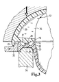
- FIG. 3 shows in detail an intake system, which is located in a welding tool.
- the welding tool lower part 30 is shown, which bears against the lower shell 10.
- the lower shell deviates slightly from the in FIG. 2 shown lower shell. However, it can be seen that in principle in the area of welding, the welding tool supports the lower shell.
- the upper shell 12 is covered by a welding tool upper part 31.
- the welding tool upper part 31 generates a directed according to arrow 27 force on the weld.
- the upper part 31 is acted upon by a transverse to the welding direction movement for heating the two contact surfaces.
- a web profile 32 is used in addition to the fixation of the upper shell 12, which engages under the shielding.
- ribs 34 are provided, which are provided at intervals from one another over the weld seam.
Landscapes
- Engineering & Computer Science (AREA)
- Mechanical Engineering (AREA)
- Chemical & Material Sciences (AREA)
- Combustion & Propulsion (AREA)
- General Engineering & Computer Science (AREA)
- Manufacturing & Machinery (AREA)
- Lining Or Joining Of Plastics Or The Like (AREA)
Abstract
Die Erfindung betrifft ein Ansaugsystem (11) für eine Brennkraftmaschine mit einer Luftzufuhröffnung und wenigstens einer Öffnung zur Abgabe der Luft an eine Brennkraftmaschine, wobei dieses aus einem thermoplastischen Kunststoff besteht und wenigstens zweiteilig aufgebaut ist. Beide Teile sind durch Reibschweißen miteinander verbunden. Zur Bildung der Schweißnaht sind auf beiden Teilen jeweils umlaufende Kontaktflächen (19,20) vorgesehen. Auf wenigstens einem Teil ist ein Fangrand (14,15) parallel zur Schweißnaht verlaufend angeordnet. Ferner weist ein Teil einen Abschirmrand auf, der ebenfalls parallel zur Schweißnaht verläuft und die Schweißnaht nach außen verdeckt.

Description
Die Erfindung betrifft ein Ansaugsystem einer Brennkraftmaschine nach dem Oberbegriff des unabhängigen Anspruches 1.The invention relates to an intake system of an internal combustion engine according to the preamble of independent claim 1.
Aus der
Es ist ferner aus der
Der Erfindung liegt die Aufgabe zugrunde, die Nachteile zu vermeiden und ein Ansaugsystem zu schaffen, welches einerseits eine zuverlässige, definierte Verbindung mehrerer Teile zueinander aufweist und andererseits optisch ansprechend gestaltet ist.The invention has for its object to avoid the disadvantages and to provide an intake system, which on the one hand has a reliable, defined connection of several parts to each other and on the other hand is designed visually appealing.
Diese Aufgabe wird ausgehend von dem Oberbegriff des unabhängigen Anspruches 1 durch dessen kennzeichnende Merkmale gelöst.This object is achieved on the basis of the preamble of the independent claim 1 by its characterizing features.
Der wesentliche Vorteil der Erfindung liegt darin, dass die Schweißnaht, die beide Teile miteinander verbindet, von außen nicht sichtbar ist, da ein Abschirmrand vorgesehen ist, der sich über die Schweißnaht erstreckt, und einen einheitlichen optischen Eindruck erzeugt.The essential advantage of the invention is that the weld that connects the two parts is not visible from the outside, since a shielding edge is provided, which extends over the weld, and produces a uniform visual impression.
Gemäß einer weiteren Ausgestaltung der Erfindung bezieht sich das zweite Teil auf einen sich über den Abschirmrand erstreckenden Abdeckrand.According to a further embodiment of the invention, the second part refers to a covering edge extending over the shielding edge.
Weiterbildungsgemäß können der Fangrand bzw. die Kontaktflächen im Bereich des Fangrandes Unterbrechungen aufweisen.According to training, the fishing edge or the contact surfaces in the region of the fishing edge may have interruptions.
Ein Verfahren zur Herstellung eines Ansaugsystems nach Anspruch 1 sieht vor, zwei Teile aus thermoplastischem Kunststoff zu bilden, die miteinander verschweißt werden, wobei zunächst das erste Teil in einer Halteform fixiert und das zweite Teil auf das erste Teil aufgelegt und durch Schwingungen angeregt wird, um eine Verschweißung zu erzielen. Zur Stabilisierung des ersten Teils sind im Schweißwerkzeug Schieber angeordnet, die dieses erste Teil von außen halten.A method for producing an intake system according to claim 1 provides to form two parts of thermoplastic material, which are welded together, wherein first the first part in a holding mold fixed and the second part is placed on the first part and excited by vibrations to achieve a weld. To stabilize the first part slides are arranged in the welding tool, which hold this first part from the outside.
Die Erfindung wird nachfolgend anhand eines Ausführungsbeispiels näher erläutert. Es zeigt:
- Figur 1
- den Stand der Technik beim Verschweißen von zwei thermoplastischen Kunststoffteilen und
- Figur 2
- die Schnittdarstellung eines Details eines Ansaugsystems und
- Figur 3
- die Darstellung gemäß
Figur 2 mit dem Ansaugsystem in einer Schweißvorrichtung.
- FIG. 1
- the prior art in the welding of two thermoplastic plastic parts and
- FIG. 2
- the sectional view of a detail of an intake system and
- FIG. 3
- the representation according to
FIG. 2 with the intake system in a welding device.
Der Abschirmrand 24 geht nahtlos in die Gehäuseform 25 über. Diese weist im Inneren Rippen 26 auf, die sich von der Gehäuseform aus bis hin zur Anlagefläche 16 erstrecken. Beim Reibschweißen wird über das Schweißwerkzeug eine Schweißkraft gemäß den Pfeilen 27 auf das Gehäuse ausgeübt. Diese Schweißkraft 27 wird über die Rippen 26 unmittelbar auf die Anlagefläche 16 übertragen.The
Die Oberschale 12 wird durch ein Schweißwerkzeugoberteil 31 umfasst. Das Schweißwerkzeugoberteil 31 erzeugt eine gemäß Pfeil 27 gerichtete Kraft auf die Verschweißung. Gleichzeitig wird das Oberteil 31 mit einer quer zur Schweißrichtung verlaufenden Bewegung zur Erwärmung der beiden Kontaktflächen beaufschlagt. Am Abschirmrand 24 wird zusätzlich zur Fixierung der Oberschale 12 ein Stegprofil 32 verwendet, das unter den Abschirmrand hindurchgreift. Zur Übertragung der Schweißkraft von dem Schweißwerkzeugoberteil 31 zur Verschweißungsposition sind Rippen 34 vorgesehen, die in Abständen voneinander über der Schweißnaht vorgesehen sind.The
Claims (5)
Applications Claiming Priority (1)
| Application Number | Priority Date | Filing Date | Title |
|---|---|---|---|
| DE200710026826 DE102007026826A1 (en) | 2007-06-06 | 2007-06-06 | intake system |
Publications (3)
| Publication Number | Publication Date |
|---|---|
| EP2000659A2 true EP2000659A2 (en) | 2008-12-10 |
| EP2000659A3 EP2000659A3 (en) | 2011-01-26 |
| EP2000659B1 EP2000659B1 (en) | 2013-03-13 |
Family
ID=39737619
Family Applications (1)
| Application Number | Title | Priority Date | Filing Date |
|---|---|---|---|
| EP20080104049 Not-in-force EP2000659B1 (en) | 2007-06-06 | 2008-05-21 | Intake system |
Country Status (2)
| Country | Link |
|---|---|
| EP (1) | EP2000659B1 (en) |
| DE (1) | DE102007026826A1 (en) |
Cited By (3)
| Publication number | Priority date | Publication date | Assignee | Title |
|---|---|---|---|---|
| WO2017025315A1 (en) | 2015-08-12 | 2017-02-16 | Etm Engineering Technologie Marketing Gmbh | Air pipe for the intake tract of an internal combustion engine |
| FR3051137A1 (en) * | 2016-05-11 | 2017-11-17 | Mahle Int Gmbh | PLASTIC HOUSING |
| DE102016221105A1 (en) | 2016-10-26 | 2018-04-26 | Etm Engineering Technologie Marketing Gmbh | Air duct for the intake tract of an internal combustion engine |
Families Citing this family (4)
| Publication number | Priority date | Publication date | Assignee | Title |
|---|---|---|---|---|
| DE102012110729A1 (en) | 2012-11-09 | 2014-05-15 | Veritas Ag | Plastic pipe |
| DE102013113737A1 (en) | 2013-12-10 | 2015-06-11 | Trelleborgvibracoustic Gmbh | Air suspension component |
| DE102015100281A1 (en) | 2015-01-09 | 2016-07-14 | Trelleborgvibracoustic Gmbh | Composite component and air spring component with such a composite component |
| EP3406889A1 (en) | 2017-05-22 | 2018-11-28 | MANN+HUMMEL GmbH | Silencer for the reduction of gas noise in an intake system of a combustion engine and a method for the production of such a silencer |
Citations (5)
| Publication number | Priority date | Publication date | Assignee | Title |
|---|---|---|---|---|
| DE19842889A1 (en) | 1997-09-22 | 1999-03-25 | Spx Corp | Welded filter with orbital vibration |
| EP1325223A1 (en) | 2000-10-14 | 2003-07-09 | Mann + Hummel GmbH | Suction pipe for an internal combustion engine, comprising at least two welded shells |
| DE102004015881A1 (en) | 2003-04-09 | 2004-12-23 | Aisan Kogyo K.K., Obu | Resin inlet manifold |
| DE102004015926A1 (en) | 2003-04-07 | 2005-01-27 | Aisan Kogyo K.K., Obu | Inlet manifold made of resin |
| WO2006046102A2 (en) | 2004-10-27 | 2006-05-04 | Toyota Jidosha Kabushiki Kaisha | Welding structure for synthetic resin intake manifold |
Family Cites Families (4)
| Publication number | Priority date | Publication date | Assignee | Title |
|---|---|---|---|---|
| GB2279035B (en) * | 1991-01-22 | 1995-06-07 | Rover Group | Fabrication of an internal combustion engine inlet manifold |
| EP0990093B1 (en) * | 1997-06-20 | 2006-09-13 | Mann + Hummel GmbH | Induction system, especially for use as an induction port of an internal combustion engine |
| US5947073A (en) * | 1998-04-06 | 1999-09-07 | Ford Global Technologies, Inc. | Adhesively bonded plastic automotive air intake assembly |
| DE20113496U1 (en) * | 2001-08-14 | 2001-10-18 | Dr.Ing.H.C. F. Porsche Ag, 70435 Stuttgart | Suction system for an internal combustion engine |
-
2007
- 2007-06-06 DE DE200710026826 patent/DE102007026826A1/en not_active Withdrawn
-
2008
- 2008-05-21 EP EP20080104049 patent/EP2000659B1/en not_active Not-in-force
Patent Citations (5)
| Publication number | Priority date | Publication date | Assignee | Title |
|---|---|---|---|---|
| DE19842889A1 (en) | 1997-09-22 | 1999-03-25 | Spx Corp | Welded filter with orbital vibration |
| EP1325223A1 (en) | 2000-10-14 | 2003-07-09 | Mann + Hummel GmbH | Suction pipe for an internal combustion engine, comprising at least two welded shells |
| DE102004015926A1 (en) | 2003-04-07 | 2005-01-27 | Aisan Kogyo K.K., Obu | Inlet manifold made of resin |
| DE102004015881A1 (en) | 2003-04-09 | 2004-12-23 | Aisan Kogyo K.K., Obu | Resin inlet manifold |
| WO2006046102A2 (en) | 2004-10-27 | 2006-05-04 | Toyota Jidosha Kabushiki Kaisha | Welding structure for synthetic resin intake manifold |
Cited By (7)
| Publication number | Priority date | Publication date | Assignee | Title |
|---|---|---|---|---|
| WO2017025315A1 (en) | 2015-08-12 | 2017-02-16 | Etm Engineering Technologie Marketing Gmbh | Air pipe for the intake tract of an internal combustion engine |
| DE102015215394A1 (en) | 2015-08-12 | 2017-02-16 | Etm Engineering Technologie Marketing Gmbh | Air duct for the intake tract of an internal combustion engine |
| US10731610B2 (en) | 2015-08-12 | 2020-08-04 | ETM Engineering Technologies Marketing GmbH | Air pipe for the intake tract of an internal combustion engine |
| FR3051137A1 (en) * | 2016-05-11 | 2017-11-17 | Mahle Int Gmbh | PLASTIC HOUSING |
| DE102016221105A1 (en) | 2016-10-26 | 2018-04-26 | Etm Engineering Technologie Marketing Gmbh | Air duct for the intake tract of an internal combustion engine |
| WO2018077737A1 (en) | 2016-10-26 | 2018-05-03 | Etm Engineering Technologie Marketing Gmbh | Air conduit for the intake tract of an internal combustion engine |
| DE102016221105B4 (en) | 2016-10-26 | 2018-05-09 | Etm Engineering Technologie Marketing Gmbh | Air duct for the intake tract of an internal combustion engine |
Also Published As
| Publication number | Publication date |
|---|---|
| DE102007026826A1 (en) | 2008-12-11 |
| EP2000659A3 (en) | 2011-01-26 |
| EP2000659B1 (en) | 2013-03-13 |
Similar Documents
| Publication | Publication Date | Title |
|---|---|---|
| EP2000659B1 (en) | Intake system | |
| DE102004014922B4 (en) | A method of manufacturing an air intake device, and an air intake device made by the method | |
| DE2159627A1 (en) | Device for deburring plastic pipes | |
| DE102007045505A1 (en) | Filter cartridge, oil filter and method of making an oil filter | |
| DE19944855A1 (en) | Intake device for an internal combustion engine | |
| DE4225735C2 (en) | Device for stretching and trimming a cylindrical part of a workpiece | |
| DE29924020U1 (en) | Sealing nozzle | |
| DE102016204025B4 (en) | Internal pressure loaded component (rail) as well as process for its production | |
| WO2000002779A1 (en) | Method for attaching a shoulder element to a bag | |
| WO2017182114A1 (en) | Bristle unit with bristle arrangement, brush with bristle unit and also apparatus and method for producing a bristle unit | |
| DE10006559A1 (en) | Grinding process and grinding machine | |
| DE202007002845U1 (en) | Drilling template for use in manufacturing of aircraft, has suction channels provided in interior of surface unit, where channels run to through holes and connection point that is accessible to unit and connects suction device to template | |
| DE19915819B4 (en) | Intake system for an internal combustion engine | |
| DE202015005290U1 (en) | nozzle assembly | |
| EP1840388A2 (en) | Method for producing an oscillating actuator | |
| DE202014001675U1 (en) | Device for filtering a plastic melt | |
| DE102004016832B4 (en) | Device for partially overmolding metallic inserts with an injection mold | |
| DE102011011215A1 (en) | Method for positively connecting two workpieces together, involves filling region of injection channel with plug after withdrawing injection tool, so that one of workpieces is welded to another workpiece | |
| EP2760604B1 (en) | Sealing arrangement for an opening in the structure of a closing element for a vehicle | |
| EP1647702B1 (en) | Intake system for internal combustion engine | |
| DE10126875A1 (en) | Welded intake device for an internal combustion engine | |
| AT402656B (en) | HYDRAULIC WORK CYLINDER HYDRAULIC WORK CYLINDER | |
| DE3234837A1 (en) | Fastener for a dust filter and dust collection part of a cleaning apparatus | |
| DE102005056374B4 (en) | Belt for transporting vessels and method for manufacturing a belt | |
| DE202008011001U1 (en) | Assembly made of plastic parts welded together |
Legal Events
| Date | Code | Title | Description |
|---|---|---|---|
| PUAI | Public reference made under article 153(3) epc to a published international application that has entered the european phase |
Free format text: ORIGINAL CODE: 0009012 |
|
| AK | Designated contracting states |
Kind code of ref document: A2 Designated state(s): AT BE BG CH CY CZ DE DK EE ES FI FR GB GR HR HU IE IS IT LI LT LU LV MC MT NL NO PL PT RO SE SI SK TR |
|
| AX | Request for extension of the european patent |
Extension state: AL BA MK RS |
|
| PUAL | Search report despatched |
Free format text: ORIGINAL CODE: 0009013 |
|
| RIC1 | Information provided on ipc code assigned before grant |
Ipc: B29C 65/00 20060101ALI20101203BHEP Ipc: F02M 35/10 20060101AFI20080918BHEP |
|
| AK | Designated contracting states |
Kind code of ref document: A3 Designated state(s): AT BE BG CH CY CZ DE DK EE ES FI FR GB GR HR HU IE IS IT LI LT LU LV MC MT NL NO PL PT RO SE SI SK TR |
|
| AX | Request for extension of the european patent |
Extension state: AL BA MK RS |
|
| 17P | Request for examination filed |
Effective date: 20110406 |
|
| AKX | Designation fees paid |
Designated state(s): AT BE BG CH CY CZ DE DK EE ES FI FR GB GR HR HU IE IS IT LI LT LU LV MC MT NL NO PL PT RO SE SI SK TR |
|
| 17Q | First examination report despatched |
Effective date: 20120309 |
|
| RIC1 | Information provided on ipc code assigned before grant |
Ipc: F02M 35/10 20060101AFI20120725BHEP Ipc: B29C 65/00 20060101ALI20120725BHEP Ipc: B29K 101/12 20060101ALI20120725BHEP Ipc: B29C 65/06 20060101ALI20120725BHEP |
|
| GRAP | Despatch of communication of intention to grant a patent |
Free format text: ORIGINAL CODE: EPIDOSNIGR1 |
|
| GRAS | Grant fee paid |
Free format text: ORIGINAL CODE: EPIDOSNIGR3 |
|
| GRAA | (expected) grant |
Free format text: ORIGINAL CODE: 0009210 |
|
| RIN1 | Information on inventor provided before grant (corrected) |
Inventor name: DIRNBERGER, TIMO Inventor name: KLATT, PETER Inventor name: KLOTZ, BERNHARD |
|
| AK | Designated contracting states |
Kind code of ref document: B1 Designated state(s): AT BE BG CH CY CZ DE DK EE ES FI FR GB GR HR HU IE IS IT LI LT LU LV MC MT NL NO PL PT RO SE SI SK TR |
|
| REG | Reference to a national code |
Ref country code: GB Ref legal event code: FG4D Free format text: NOT ENGLISH |
|
| REG | Reference to a national code |
Ref country code: CH Ref legal event code: EP Ref country code: AT Ref legal event code: REF Ref document number: 600947 Country of ref document: AT Kind code of ref document: T Effective date: 20130315 |
|
| REG | Reference to a national code |
Ref country code: IE Ref legal event code: FG4D Free format text: LANGUAGE OF EP DOCUMENT: GERMAN |
|
| REG | Reference to a national code |
Ref country code: DE Ref legal event code: R096 Ref document number: 502008009452 Country of ref document: DE Effective date: 20130508 |
|
| PG25 | Lapsed in a contracting state [announced via postgrant information from national office to epo] |
Ref country code: NO Free format text: LAPSE BECAUSE OF FAILURE TO SUBMIT A TRANSLATION OF THE DESCRIPTION OR TO PAY THE FEE WITHIN THE PRESCRIBED TIME-LIMIT Effective date: 20130613 Ref country code: SE Free format text: LAPSE BECAUSE OF FAILURE TO SUBMIT A TRANSLATION OF THE DESCRIPTION OR TO PAY THE FEE WITHIN THE PRESCRIBED TIME-LIMIT Effective date: 20130313 Ref country code: ES Free format text: LAPSE BECAUSE OF FAILURE TO SUBMIT A TRANSLATION OF THE DESCRIPTION OR TO PAY THE FEE WITHIN THE PRESCRIBED TIME-LIMIT Effective date: 20130624 Ref country code: LT Free format text: LAPSE BECAUSE OF FAILURE TO SUBMIT A TRANSLATION OF THE DESCRIPTION OR TO PAY THE FEE WITHIN THE PRESCRIBED TIME-LIMIT Effective date: 20130313 Ref country code: BG Free format text: LAPSE BECAUSE OF FAILURE TO SUBMIT A TRANSLATION OF THE DESCRIPTION OR TO PAY THE FEE WITHIN THE PRESCRIBED TIME-LIMIT Effective date: 20130613 |
|
| REG | Reference to a national code |
Ref country code: NL Ref legal event code: VDEP Effective date: 20130313 |
|
| REG | Reference to a national code |
Ref country code: LT Ref legal event code: MG4D |
|
| PG25 | Lapsed in a contracting state [announced via postgrant information from national office to epo] |
Ref country code: LV Free format text: LAPSE BECAUSE OF FAILURE TO SUBMIT A TRANSLATION OF THE DESCRIPTION OR TO PAY THE FEE WITHIN THE PRESCRIBED TIME-LIMIT Effective date: 20130313 Ref country code: GR Free format text: LAPSE BECAUSE OF FAILURE TO SUBMIT A TRANSLATION OF THE DESCRIPTION OR TO PAY THE FEE WITHIN THE PRESCRIBED TIME-LIMIT Effective date: 20130614 Ref country code: FI Free format text: LAPSE BECAUSE OF FAILURE TO SUBMIT A TRANSLATION OF THE DESCRIPTION OR TO PAY THE FEE WITHIN THE PRESCRIBED TIME-LIMIT Effective date: 20130313 Ref country code: SI Free format text: LAPSE BECAUSE OF FAILURE TO SUBMIT A TRANSLATION OF THE DESCRIPTION OR TO PAY THE FEE WITHIN THE PRESCRIBED TIME-LIMIT Effective date: 20130313 |
|
| PG25 | Lapsed in a contracting state [announced via postgrant information from national office to epo] |
Ref country code: HR Free format text: LAPSE BECAUSE OF FAILURE TO SUBMIT A TRANSLATION OF THE DESCRIPTION OR TO PAY THE FEE WITHIN THE PRESCRIBED TIME-LIMIT Effective date: 20130313 |
|
| PG25 | Lapsed in a contracting state [announced via postgrant information from national office to epo] |
Ref country code: SK Free format text: LAPSE BECAUSE OF FAILURE TO SUBMIT A TRANSLATION OF THE DESCRIPTION OR TO PAY THE FEE WITHIN THE PRESCRIBED TIME-LIMIT Effective date: 20130313 Ref country code: IS Free format text: LAPSE BECAUSE OF FAILURE TO SUBMIT A TRANSLATION OF THE DESCRIPTION OR TO PAY THE FEE WITHIN THE PRESCRIBED TIME-LIMIT Effective date: 20130713 Ref country code: RO Free format text: LAPSE BECAUSE OF FAILURE TO SUBMIT A TRANSLATION OF THE DESCRIPTION OR TO PAY THE FEE WITHIN THE PRESCRIBED TIME-LIMIT Effective date: 20130313 Ref country code: NL Free format text: LAPSE BECAUSE OF FAILURE TO SUBMIT A TRANSLATION OF THE DESCRIPTION OR TO PAY THE FEE WITHIN THE PRESCRIBED TIME-LIMIT Effective date: 20130313 Ref country code: PT Free format text: LAPSE BECAUSE OF FAILURE TO SUBMIT A TRANSLATION OF THE DESCRIPTION OR TO PAY THE FEE WITHIN THE PRESCRIBED TIME-LIMIT Effective date: 20130715 Ref country code: EE Free format text: LAPSE BECAUSE OF FAILURE TO SUBMIT A TRANSLATION OF THE DESCRIPTION OR TO PAY THE FEE WITHIN THE PRESCRIBED TIME-LIMIT Effective date: 20130313 Ref country code: CZ Free format text: LAPSE BECAUSE OF FAILURE TO SUBMIT A TRANSLATION OF THE DESCRIPTION OR TO PAY THE FEE WITHIN THE PRESCRIBED TIME-LIMIT Effective date: 20130313 |
|
| PG25 | Lapsed in a contracting state [announced via postgrant information from national office to epo] |
Ref country code: PL Free format text: LAPSE BECAUSE OF FAILURE TO SUBMIT A TRANSLATION OF THE DESCRIPTION OR TO PAY THE FEE WITHIN THE PRESCRIBED TIME-LIMIT Effective date: 20130313 Ref country code: CY Free format text: LAPSE BECAUSE OF FAILURE TO SUBMIT A TRANSLATION OF THE DESCRIPTION OR TO PAY THE FEE WITHIN THE PRESCRIBED TIME-LIMIT Effective date: 20130313 |
|
| BERE | Be: lapsed |
Owner name: MANN+HUMMEL G.M.B.H. Effective date: 20130531 |
|
| PG25 | Lapsed in a contracting state [announced via postgrant information from national office to epo] |
Ref country code: MC Free format text: LAPSE BECAUSE OF FAILURE TO SUBMIT A TRANSLATION OF THE DESCRIPTION OR TO PAY THE FEE WITHIN THE PRESCRIBED TIME-LIMIT Effective date: 20130313 |
|
| REG | Reference to a national code |
Ref country code: CH Ref legal event code: PL |
|
| PLBE | No opposition filed within time limit |
Free format text: ORIGINAL CODE: 0009261 |
|
| STAA | Information on the status of an ep patent application or granted ep patent |
Free format text: STATUS: NO OPPOSITION FILED WITHIN TIME LIMIT |
|
| PG25 | Lapsed in a contracting state [announced via postgrant information from national office to epo] |
Ref country code: DK Free format text: LAPSE BECAUSE OF FAILURE TO SUBMIT A TRANSLATION OF THE DESCRIPTION OR TO PAY THE FEE WITHIN THE PRESCRIBED TIME-LIMIT Effective date: 20130313 Ref country code: LI Free format text: LAPSE BECAUSE OF NON-PAYMENT OF DUE FEES Effective date: 20130531 Ref country code: CH Free format text: LAPSE BECAUSE OF NON-PAYMENT OF DUE FEES Effective date: 20130531 |
|
| 26N | No opposition filed |
Effective date: 20131216 |
|
| GBPC | Gb: european patent ceased through non-payment of renewal fee |
Effective date: 20130613 |
|
| REG | Reference to a national code |
Ref country code: IE Ref legal event code: MM4A |
|
| PG25 | Lapsed in a contracting state [announced via postgrant information from national office to epo] |
Ref country code: IT Free format text: LAPSE BECAUSE OF FAILURE TO SUBMIT A TRANSLATION OF THE DESCRIPTION OR TO PAY THE FEE WITHIN THE PRESCRIBED TIME-LIMIT Effective date: 20130313 Ref country code: BE Free format text: LAPSE BECAUSE OF NON-PAYMENT OF DUE FEES Effective date: 20130531 |
|
| REG | Reference to a national code |
Ref country code: FR Ref legal event code: ST Effective date: 20140131 |
|
| REG | Reference to a national code |
Ref country code: DE Ref legal event code: R097 Ref document number: 502008009452 Country of ref document: DE Effective date: 20131216 |
|
| PG25 | Lapsed in a contracting state [announced via postgrant information from national office to epo] |
Ref country code: IE Free format text: LAPSE BECAUSE OF NON-PAYMENT OF DUE FEES Effective date: 20130521 Ref country code: GB Free format text: LAPSE BECAUSE OF NON-PAYMENT OF DUE FEES Effective date: 20130613 |
|
| PG25 | Lapsed in a contracting state [announced via postgrant information from national office to epo] |
Ref country code: FR Free format text: LAPSE BECAUSE OF NON-PAYMENT OF DUE FEES Effective date: 20130531 |
|
| REG | Reference to a national code |
Ref country code: AT Ref legal event code: MM01 Ref document number: 600947 Country of ref document: AT Kind code of ref document: T Effective date: 20130521 |
|
| PG25 | Lapsed in a contracting state [announced via postgrant information from national office to epo] |
Ref country code: AT Free format text: LAPSE BECAUSE OF NON-PAYMENT OF DUE FEES Effective date: 20130521 |
|
| PG25 | Lapsed in a contracting state [announced via postgrant information from national office to epo] |
Ref country code: MT Free format text: LAPSE BECAUSE OF FAILURE TO SUBMIT A TRANSLATION OF THE DESCRIPTION OR TO PAY THE FEE WITHIN THE PRESCRIBED TIME-LIMIT Effective date: 20130313 |
|
| PG25 | Lapsed in a contracting state [announced via postgrant information from national office to epo] |
Ref country code: TR Free format text: LAPSE BECAUSE OF FAILURE TO SUBMIT A TRANSLATION OF THE DESCRIPTION OR TO PAY THE FEE WITHIN THE PRESCRIBED TIME-LIMIT Effective date: 20130313 |
|
| PG25 | Lapsed in a contracting state [announced via postgrant information from national office to epo] |
Ref country code: LU Free format text: LAPSE BECAUSE OF NON-PAYMENT OF DUE FEES Effective date: 20130521 Ref country code: HU Free format text: LAPSE BECAUSE OF FAILURE TO SUBMIT A TRANSLATION OF THE DESCRIPTION OR TO PAY THE FEE WITHIN THE PRESCRIBED TIME-LIMIT; INVALID AB INITIO Effective date: 20080521 |
|
| REG | Reference to a national code |
Ref country code: DE Ref legal event code: R081 Ref document number: 502008009452 Country of ref document: DE Owner name: MANN+HUMMEL GMBH, DE Free format text: FORMER OWNER: MANN + HUMMEL GMBH, 71638 LUDWIGSBURG, DE |
|
| REG | Reference to a national code |
Ref country code: DE Ref legal event code: R081 Ref document number: 502008009452 Country of ref document: DE Owner name: MOLDTECS-01-2022 GMBH, DE Free format text: FORMER OWNER: MANN+HUMMEL GMBH, 71636 LUDWIGSBURG, DE |
|
| PGFP | Annual fee paid to national office [announced via postgrant information from national office to epo] |
Ref country code: DE Payment date: 20220620 Year of fee payment: 16 |
|
| P01 | Opt-out of the competence of the unified patent court (upc) registered |
Effective date: 20240220 |
|
| REG | Reference to a national code |
Ref country code: DE Ref legal event code: R119 Ref document number: 502008009452 Country of ref document: DE |
|
| PG25 | Lapsed in a contracting state [announced via postgrant information from national office to epo] |
Ref country code: DE Free format text: LAPSE BECAUSE OF NON-PAYMENT OF DUE FEES Effective date: 20241203 |