EP2000678A9 - Boulon de diamètre variable résistant au cisaillement et à la traction - Google Patents
Boulon de diamètre variable résistant au cisaillement et à la traction Download PDFInfo
- Publication number
- EP2000678A9 EP2000678A9 EP07730360A EP07730360A EP2000678A9 EP 2000678 A9 EP2000678 A9 EP 2000678A9 EP 07730360 A EP07730360 A EP 07730360A EP 07730360 A EP07730360 A EP 07730360A EP 2000678 A9 EP2000678 A9 EP 2000678A9
- Authority
- EP
- European Patent Office
- Prior art keywords
- tapered
- bolt
- surface area
- joined
- coupling means
- Prior art date
- Legal status (The legal status is an assumption and is not a legal conclusion. Google has not performed a legal analysis and makes no representation as to the accuracy of the status listed.)
- Withdrawn
Links
Images
Classifications
-
- F—MECHANICAL ENGINEERING; LIGHTING; HEATING; WEAPONS; BLASTING
- F16—ENGINEERING ELEMENTS AND UNITS; GENERAL MEASURES FOR PRODUCING AND MAINTAINING EFFECTIVE FUNCTIONING OF MACHINES OR INSTALLATIONS; THERMAL INSULATION IN GENERAL
- F16B—DEVICES FOR FASTENING OR SECURING CONSTRUCTIONAL ELEMENTS OR MACHINE PARTS TOGETHER, e.g. NAILS, BOLTS, CIRCLIPS, CLAMPS, CLIPS OR WEDGES; JOINTS OR JOINTING
- F16B3/00—Key-type connections; Keys
- F16B3/06—Key-type connections; Keys using taper sleeves
-
- F—MECHANICAL ENGINEERING; LIGHTING; HEATING; WEAPONS; BLASTING
- F16—ENGINEERING ELEMENTS AND UNITS; GENERAL MEASURES FOR PRODUCING AND MAINTAINING EFFECTIVE FUNCTIONING OF MACHINES OR INSTALLATIONS; THERMAL INSULATION IN GENERAL
- F16B—DEVICES FOR FASTENING OR SECURING CONSTRUCTIONAL ELEMENTS OR MACHINE PARTS TOGETHER, e.g. NAILS, BOLTS, CIRCLIPS, CLAMPS, CLIPS OR WEDGES; JOINTS OR JOINTING
- F16B19/00—Bolts without screw-thread; Pins, including deformable elements; Rivets
- F16B19/02—Bolts or sleeves for positioning of machine parts, e.g. notched taper pins, fitting pins, sleeves, eccentric positioning rings
-
- F—MECHANICAL ENGINEERING; LIGHTING; HEATING; WEAPONS; BLASTING
- F16—ENGINEERING ELEMENTS AND UNITS; GENERAL MEASURES FOR PRODUCING AND MAINTAINING EFFECTIVE FUNCTIONING OF MACHINES OR INSTALLATIONS; THERMAL INSULATION IN GENERAL
- F16B—DEVICES FOR FASTENING OR SECURING CONSTRUCTIONAL ELEMENTS OR MACHINE PARTS TOGETHER, e.g. NAILS, BOLTS, CIRCLIPS, CLAMPS, CLIPS OR WEDGES; JOINTS OR JOINTING
- F16B35/00—Screw-bolts; Stay-bolts; Screw-threaded studs; Screws; Set screws
- F16B35/04—Screw-bolts; Stay-bolts; Screw-threaded studs; Screws; Set screws with specially-shaped head or shaft in order to fix the bolt on or in an object
- F16B35/041—Specially-shaped shafts
-
- F—MECHANICAL ENGINEERING; LIGHTING; HEATING; WEAPONS; BLASTING
- F16—ENGINEERING ELEMENTS AND UNITS; GENERAL MEASURES FOR PRODUCING AND MAINTAINING EFFECTIVE FUNCTIONING OF MACHINES OR INSTALLATIONS; THERMAL INSULATION IN GENERAL
- F16B—DEVICES FOR FASTENING OR SECURING CONSTRUCTIONAL ELEMENTS OR MACHINE PARTS TOGETHER, e.g. NAILS, BOLTS, CIRCLIPS, CLAMPS, CLIPS OR WEDGES; JOINTS OR JOINTING
- F16B5/00—Joining sheets or plates, e.g. panels, to one another or to strips or bars parallel to them
- F16B5/02—Joining sheets or plates, e.g. panels, to one another or to strips or bars parallel to them by means of fastening members using screw-thread
Definitions
- the present invention refers to a shear and draw bolt which, being of adjustable diameter, may fit tightly into holes of the parts to be joined, thus reducing the number and/or diameter of the coupling elements.
- Use of the bolts of the invention successfully decreases the weight of joints and, thereby, that of the structures of which they form part.
- Another advantage is that the machining jobs are fewer (fewer drill holes) with the consequent economic saving and greater ease of assembly, so that the time of this is shortened and its cost lowered.
- the joint is usually designed with a ratio between the diameter of the bolts and the thickness of the plates, such that the bolts needed may be approximately the same in accordance with the hypothesis that failure of the joint may occur because of crushing or shear.
- ⁇ adm ⁇ ⁇ i
- ⁇ i the strength of the steel and values of 0.80 are usually accepted for ⁇ in tight fitting bolts and 0.65 for bolts with a clearance of 1 mm.
- ⁇ o adm ⁇ ⁇ u
- ⁇ u is the strength for the plate and values of 2 are usually accepted for bolts with clearance and 2.5 for bolts with no clearance (calibrated).
- An aim of the present invention is to make bolts available which, while in pure shear stress, can be used as spring pins, susceptible to be fitted and removed easily and repeatedly.
- the other aim of the present invention is to make bolts available which, while in shear stress, can also be used as draw bolts.
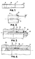
- the solution proposed consists of using a tapered male bolt that presents a frustoconical surface and a tapered female bushing, provided with axial slots open alternately on each side of the bushing and whose lower frustoconical surface area adapts to that of the tapered male bolt.
- the use of coupling means enables the male bolt to be inserted into the female bushing, bringing about an expansion in the latter's outside diameter.
- the above-mentioned coupling means may vary considerably depending on the design specifications of the joint, and they may consist of nuts, screws, preformed hexagonal heads, etc.
- means may be provided for retaining the axial movements of the tapered female bushing, so this may incorporate a perimeter flange or else it may be fitted with a step by way of a stop in the hole of the parts to be joined.
- the bolt of the invention may also be provided with pulling means that enable it to act as a draw bolt, pressing the parts to be joined against one another.
- the advantages of the bolt of the invention stem from the fact that its use in shearing joints and in joints subject to high shear stress may dispense with the fitting of draw bolts, besides ensuring that in those in which they are used only the other stresses have to be absorbed, with the reduction of the number of these and of their dies, thereby making the joints lighter and facilitating installation, as the holes are smaller and the bolt tightening torques lower too. Lastly, we have to take into account the cost and time saving that they bring, as fewer holes have to be made at each joint.
- the device of the invention consists of a tapered male bolt (1), which presents a frustoconical surface area (8), terminating in a cylindrical end (7) matching up with its larger diameter side, on which there is fitted a tapered female bushing (2) whose inner surface presents the same conicity ⁇ as the outer surface of the tapered male bolt (1) and a series of axial slots (3), open alternately on each side of the bushing.
- the tapered male bolt (1) presents an inner hexagonal head (10) and its threaded end (6) engages in a threaded housing (11) presented by one of the parts to be joined (9).
- the tapered female bushing (2) is expanded as it is prevented from moving along the parts to be joined (9) by a stop (12).
- this version there is a relative rotary movement between the tapered male bolt (1) and the tapered female bushing (2), but in compensation the nut (4) disappears from the outside of the coupling. See figure 4 .
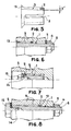
- the stop (12) is dispensed with and it is replaced by means for retaining the tapered female bushing (2), which, in this case, presents a flange (13) that engages with a bevel on the respective part to be joined (9).
- the outer threading (6) is replaced by an inner threading (14) at the cylindrical end (7) of the tapered bolt (1).
- the coupling means are composed of a screw (15), which engages in the inner threading (14) and rests on the tapered female bushing (2) by way of a washer (5).
- pure expansion of the outside diameter of the tapered female bushing (2) takes place and there is no relative rotation between this and the tapered male bolt (1). Tightening between the parts to be joined (9) does not take place either. See figure 7 .
- a screw (15) is provided that applies pressure by way of a washer (5) and engages in an inner threading (14) presented by the cylindrical end of the tapered male bolt (1).
- the pulling screw effect is separated from the shear pin effect, as we have two different adjusting elements: the nut (4) and the screw (15).
- the bolt of the invention is designed for any simple or combined shear application or joints with a high shearing stress. It may also be used as an insertable and removable spring pin.
- the different designs described are defined in their sizing by the specific application and their mechanical stresses. They may also be designed and sized by standardizing dimensions and loads to be borne for specific applications, as their use is universal.
- the tapered female bushing may be designed in accordance with the application and calculations, always with a view to its anchorage in the joint and its best deformation:
- the bolt is also designed in accordance with the application and the calculations of this and with a view to optimum performance and ease of fitting, with different design options (knurling, milling, etc.)
- the tips may be finished with different threads, different kinds of head (hexagonal, Allen, socket, slotted, etc.) according to international nut and bolt standards options and their applications.
- the materials to be used shall always be those that assure the mechanical response to the demands of the joint. These materials may have different heat treatments, hardnesses, surface, anticorrosion, lubricant, self-locking, etc. treatments.
Landscapes
- Engineering & Computer Science (AREA)
- General Engineering & Computer Science (AREA)
- Mechanical Engineering (AREA)
- Connection Of Plates (AREA)
Applications Claiming Priority (2)
| Application Number | Priority Date | Filing Date | Title |
|---|---|---|---|
| ES200600684U ES1062476Y (es) | 2006-03-24 | 2006-03-24 | Perno a cortadura y traccion de diametro variable |
| PCT/ES2007/000119 WO2007110455A1 (fr) | 2006-03-24 | 2007-03-07 | Boulon de diamètre variable résistant au cisaillement et à la traction |
Publications (2)
| Publication Number | Publication Date |
|---|---|
| EP2000678A2 EP2000678A2 (fr) | 2008-12-10 |
| EP2000678A9 true EP2000678A9 (fr) | 2009-03-18 |
Family
ID=36593577
Family Applications (1)
| Application Number | Title | Priority Date | Filing Date |
|---|---|---|---|
| EP07730360A Withdrawn EP2000678A2 (fr) | 2006-03-24 | 2007-03-07 | Boulon de diamètre variable résistant au cisaillement et à la traction |
Country Status (5)
| Country | Link |
|---|---|
| US (1) | US20090202316A1 (fr) |
| EP (1) | EP2000678A2 (fr) |
| ES (1) | ES1062476Y (fr) |
| TW (1) | TWM319336U (fr) |
| WO (1) | WO2007110455A1 (fr) |
Families Citing this family (7)
| Publication number | Priority date | Publication date | Assignee | Title |
|---|---|---|---|---|
| US8057145B2 (en) * | 2008-06-26 | 2011-11-15 | Jetyd Corp. | Radially expanding bolt assembly |
| DE202008013896U1 (de) * | 2008-10-17 | 2010-03-11 | Liebherr-Hydraulikbagger Gmbh | Verfahrbares Arbeitsgerät |
| US20140112732A1 (en) * | 2012-10-19 | 2014-04-24 | Electro-Motive Diesel, Inc. | Expanding Dowel Rod Structure |
| CN107312462B (zh) * | 2017-07-31 | 2022-06-24 | 太仓市众翔精密五金有限公司 | 一种防水耐用紧固铆钉烤漆件及其加工工艺 |
| WO2019076446A1 (fr) * | 2017-10-18 | 2019-04-25 | Heico Befestigungstechnik Gmbh | Boulon d'écartement et ensemble de liaison comportant un tel boulon d'écartement |
| CA3077491A1 (fr) | 2020-03-30 | 2021-09-30 | Plainsman Mfg. Inc. | Accouplement a chevilles et methode d`assemblage |
| ES3024409A1 (es) * | 2023-12-04 | 2025-06-04 | Airbus Operations Slu | Sistema de union |
Family Cites Families (5)
| Publication number | Priority date | Publication date | Assignee | Title |
|---|---|---|---|---|
| US1823428A (en) * | 1930-02-14 | 1931-09-15 | Nat Supply Co | Anchorage device |
| US2100873A (en) * | 1935-12-28 | 1937-11-30 | Russell M Roberts | Dowel structure |
| US3298725A (en) * | 1964-10-01 | 1967-01-17 | John C Boteler | High-strength fastener |
| DE1750905A1 (de) * | 1968-06-18 | 1970-12-23 | Renner Dipl Ing Ewald | Spreizhuelse zu Kegelstift und Kegelpassschraube |
| US3503638A (en) * | 1968-09-24 | 1970-03-31 | Willy Holzel | Guide column and tool frame assembly |
-
2006
- 2006-03-24 ES ES200600684U patent/ES1062476Y/es not_active Expired - Fee Related
-
2007
- 2007-03-07 US US12/294,272 patent/US20090202316A1/en not_active Abandoned
- 2007-03-07 EP EP07730360A patent/EP2000678A2/fr not_active Withdrawn
- 2007-03-07 WO PCT/ES2007/000119 patent/WO2007110455A1/fr not_active Ceased
- 2007-03-23 TW TW096204727U patent/TWM319336U/zh not_active IP Right Cessation
Also Published As
| Publication number | Publication date |
|---|---|
| ES1062476Y (es) | 2006-09-16 |
| WO2007110455A1 (fr) | 2007-10-04 |
| TWM319336U (en) | 2007-09-21 |
| ES1062476U (es) | 2006-06-16 |
| US20090202316A1 (en) | 2009-08-13 |
| EP2000678A2 (fr) | 2008-12-10 |
Similar Documents
| Publication | Publication Date | Title |
|---|---|---|
| EP2000678A2 (fr) | Boulon de diamètre variable résistant au cisaillement et à la traction | |
| US20070243037A1 (en) | Blind bolt fastener | |
| US7857563B2 (en) | Mechanically locked blind bolt fastener | |
| US20130061452A1 (en) | Fastener and method of installing same | |
| US3682508A (en) | Re-usable, spin-stopping fastener | |
| CA2282712C (fr) | Ecrou libre a couple dominant | |
| US11585364B2 (en) | Blind fastener | |
| US4050833A (en) | Taper headed fastener to increase work fatigue life | |
| JP2002519598A (ja) | 締付荷重を決定可能なねじ締付具 | |
| US11867212B2 (en) | Deformable sleeve nut and a method of manufacturing | |
| JPH116513A (ja) | 改良されたブラインドナット | |
| US5350264A (en) | Blind fastener with reinforced containment sleeve | |
| US5860778A (en) | Torque- and preload-controlled fastener and associated method of fastening | |
| TW202530558A (zh) | 用於緊固件裝置的配合對準裝置 | |
| EP1353080B1 (fr) | Elément à limitation de couple intrinsèque pour un goujon expansible | |
| JP2023113399A (ja) | 摩擦接合用添板 | |
| DE10325431A1 (de) | Verbindungsanordnung zweier Bauteile mit einem Blindniet und Verfahren zum Vernieten zweier Bauteile | |
| DE102010024619B4 (de) | Vorgespanntes Differentialgetriebe ohne Zahnflankenwechsel | |
| US8544366B2 (en) | Spark plug removal tool apparatus | |
| DE102023002927A1 (de) | Schraubenmutter zum selbstschneidenden Einschrauben in vorgebohrte Fahrzeug- und Flugzeugteile mit einseitigem Zugang | |
| EP0477860A1 (fr) | Elément de fixation aveugle avec écrou d'entraînement | |
| CN116044883B (zh) | 一种螺母自锁方法及其自锁结构 | |
| EP1360432A2 (fr) | Element de fixation central pour ressort a gaz a symetrie de rotation | |
| EP2528796B1 (fr) | Plaque de support présentant une fixation par vis | |
| DE102004018800A1 (de) | Montageeinheit mit einer Nietverbindung |
Legal Events
| Date | Code | Title | Description |
|---|---|---|---|
| PUAI | Public reference made under article 153(3) epc to a published international application that has entered the european phase |
Free format text: ORIGINAL CODE: 0009012 |
|
| 17P | Request for examination filed |
Effective date: 20080922 |
|
| AK | Designated contracting states |
Kind code of ref document: A2 Designated state(s): AT BE BG CH CY CZ DE DK EE ES FI FR GB GR HU IE IS IT LI LT LU LV MC MT NL PL PT RO SE SI SK TR |
|
| PUAB | Information related to the publication of an a document modified or deleted |
Free format text: ORIGINAL CODE: 0009199EPPU |
|
| STAA | Information on the status of an ep patent application or granted ep patent |
Free format text: STATUS: THE APPLICATION IS DEEMED TO BE WITHDRAWN |
|
| 18D | Application deemed to be withdrawn |
Effective date: 20111001 |