EP2000694B1 - Insert et dispositf de retenue pour sa fixation sur un disque de frein d'avion - Google Patents
Insert et dispositf de retenue pour sa fixation sur un disque de frein d'avion Download PDFInfo
- Publication number
- EP2000694B1 EP2000694B1 EP08157375A EP08157375A EP2000694B1 EP 2000694 B1 EP2000694 B1 EP 2000694B1 EP 08157375 A EP08157375 A EP 08157375A EP 08157375 A EP08157375 A EP 08157375A EP 2000694 B1 EP2000694 B1 EP 2000694B1
- Authority
- EP
- European Patent Office
- Prior art keywords
- insert
- notch
- retainer
- walls
- rotor
- Prior art date
- Legal status (The legal status is an assumption and is not a legal conclusion. Google has not performed a legal analysis and makes no representation as to the accuracy of the status listed.)
- Not-in-force
Links
- 230000002093 peripheral effect Effects 0.000 claims description 30
- 238000000034 method Methods 0.000 claims description 4
- 230000014759 maintenance of location Effects 0.000 claims 2
- OKTJSMMVPCPJKN-UHFFFAOYSA-N Carbon Chemical compound [C] OKTJSMMVPCPJKN-UHFFFAOYSA-N 0.000 description 5
- 229910052799 carbon Inorganic materials 0.000 description 5
- 230000000717 retained effect Effects 0.000 description 4
- 229910000831 Steel Inorganic materials 0.000 description 3
- 239000010959 steel Substances 0.000 description 3
- 238000007792 addition Methods 0.000 description 2
- 239000000463 material Substances 0.000 description 2
- 238000012986 modification Methods 0.000 description 2
- 230000004048 modification Effects 0.000 description 2
- 229920000049 Carbon (fiber) Polymers 0.000 description 1
- CREMABGTGYGIQB-UHFFFAOYSA-N carbon carbon Chemical compound C.C CREMABGTGYGIQB-UHFFFAOYSA-N 0.000 description 1
- 239000004917 carbon fiber Substances 0.000 description 1
- 239000011203 carbon fibre reinforced carbon Substances 0.000 description 1
- 239000003575 carbonaceous material Substances 0.000 description 1
- 230000000295 complement effect Effects 0.000 description 1
- 239000011159 matrix material Substances 0.000 description 1
- 239000002184 metal Substances 0.000 description 1
- VNWKTOKETHGBQD-UHFFFAOYSA-N methane Chemical compound C VNWKTOKETHGBQD-UHFFFAOYSA-N 0.000 description 1
- 230000003014 reinforcing effect Effects 0.000 description 1
Images


Classifications
-
- F—MECHANICAL ENGINEERING; LIGHTING; HEATING; WEAPONS; BLASTING
- F16—ENGINEERING ELEMENTS AND UNITS; GENERAL MEASURES FOR PRODUCING AND MAINTAINING EFFECTIVE FUNCTIONING OF MACHINES OR INSTALLATIONS; THERMAL INSULATION IN GENERAL
- F16D—COUPLINGS FOR TRANSMITTING ROTATION; CLUTCHES; BRAKES
- F16D65/00—Parts or details
- F16D65/02—Braking members; Mounting thereof
- F16D65/12—Discs; Drums for disc brakes
- F16D65/125—Discs; Drums for disc brakes characterised by the material used for the disc body
- F16D65/126—Discs; Drums for disc brakes characterised by the material used for the disc body the material being of low mechanical strength, e.g. carbon, beryllium; Torque transmitting members therefor
-
- F—MECHANICAL ENGINEERING; LIGHTING; HEATING; WEAPONS; BLASTING
- F16—ENGINEERING ELEMENTS AND UNITS; GENERAL MEASURES FOR PRODUCING AND MAINTAINING EFFECTIVE FUNCTIONING OF MACHINES OR INSTALLATIONS; THERMAL INSULATION IN GENERAL
- F16D—COUPLINGS FOR TRANSMITTING ROTATION; CLUTCHES; BRAKES
- F16D55/00—Brakes with substantially-radial braking surfaces pressed together in axial direction, e.g. disc brakes
- F16D2055/0004—Parts or details of disc brakes
- F16D2055/0058—Fully lined, i.e. braking surface extending over the entire disc circumference
-
- F—MECHANICAL ENGINEERING; LIGHTING; HEATING; WEAPONS; BLASTING
- F16—ENGINEERING ELEMENTS AND UNITS; GENERAL MEASURES FOR PRODUCING AND MAINTAINING EFFECTIVE FUNCTIONING OF MACHINES OR INSTALLATIONS; THERMAL INSULATION IN GENERAL
- F16D—COUPLINGS FOR TRANSMITTING ROTATION; CLUTCHES; BRAKES
- F16D65/00—Parts or details
- F16D65/02—Braking members; Mounting thereof
- F16D2065/13—Parts or details of discs or drums
- F16D2065/134—Connection
- F16D2065/1356—Connection interlocking
- F16D2065/1364—Connection interlocking with relative movement axially
-
- F—MECHANICAL ENGINEERING; LIGHTING; HEATING; WEAPONS; BLASTING
- F16—ENGINEERING ELEMENTS AND UNITS; GENERAL MEASURES FOR PRODUCING AND MAINTAINING EFFECTIVE FUNCTIONING OF MACHINES OR INSTALLATIONS; THERMAL INSULATION IN GENERAL
- F16D—COUPLINGS FOR TRANSMITTING ROTATION; CLUTCHES; BRAKES
- F16D2200/00—Materials; Production methods therefor
- F16D2200/0034—Materials; Production methods therefor non-metallic
- F16D2200/0039—Ceramics
Definitions
- the present invention is directed toward an aircraft brake disk having one or more load distributing inserts and retainers for securing the inserts to the brake disk, and, more specifically, toward an aircraft brake disk having one or more load distributing inserts which inserts are radially retained by engagement with the brake disk and axially retained by a retainer which arrangement reduces or eliminates the need to rivet the retainer to the brake disk.
- Brake rotors and stators are sometimes formed from steel.
- carbon materials may comprise, for example, carbon embedded in a carbon fiber matrix, which material may be referred to generically as "carbon” or "carbon-carbon.”
- Carbon brake disks may also include notches in their outer peripheral walls for accommodating drive keys and in their inner peripheral walls for accommodating torque tube splines.
- these notches also typically include inserts to better distribute the load from the drive keys and/or splines to the rotor or stator and to reduce wear on the carbon brake disks. These inserts are typically formed from steel.
- EP-A-0 161 200 discloses a friction brake disk having a plurality of T-shape slots at a peripheral edge of the brake disk and each slot carries a metallic insert member.
- the insert member has the same T-shape and is configured to be inserted in the slot in the axial direction of the disk but restrained from being removed in the radial direction.
- a retaining clip is fastened to the insert member using fasteners for preventing movement in the axial direction by the insert member.
- GB-A-2 139 300 discloses a brake disk having an outer periphery with slots. Each slot receives a reinforcing insert. The inserts are U-shaped and are retained in their respective slots by clips secured to the disk adjacent to the slots.
- Inserts and retainers such as those described above perform in an acceptable manner.
- a typical rotor disk may have eight to twelve outer peripheral notches, and each retainer often requires about three rivets to secure. It is therefore necessary, in some cases, to drill about 36 openings, align those openings with openings in the retainers, and secure rivets in each of the openings. Similar difficulties are presented when installing inserts in stator inner peripheral walls. Such procedures add to the cost and complexity of rotor and stator assembly. It would therefore be desirable to reduce or eliminate the use of rivets when connecting inserts to rotor or stator disks.
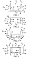
- Figure 2 is a top plan view of the rotor insert of Figure 1 ;
- Figure 3 is a side elevational view of a retainer for holding an insert according to an embodiment of the present invention in a rotor;
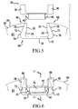
- Figure 5 illustrates the retainer of Figure 3 being connected to the insert of Figure 1 after the insert of Figure 1 has been inserted into a notch in a rotor disk;
- Figure 6 is a side elevational view of the insert of Figure 1 mounted in a peripheral notch in a rotor disk and secured to the disk with the retainer of Figure 3 ;
- Figure 8 is a side elevational view of a rotor, insert and retainer according to another embodiment of the present invention.
- Figure 9 is a side elevational view of a rotor, insert and retainer according to another embodiment of the present invention.
- Figure 10 is a side elevational view of the insert of Figure 1 mounted in a peripheral notch of a stator
- Figure 11 illustrates a conventional rotor insert and retainer connected to a rotor disk by rivets.
- insert 10 can be axially inserted in notch 66; however, because the body 12 of insert 10 is wider than the portion of insert 10 at the ends 16 of legs 14, the insert cannot be radially inserted or removed.
- the engagement between insert 10 and notch 66 substantially prevents radially relative movement between the insert 10 and the rotor disk 60.
- Retainer 30 is then connected to insert 10 by moving central body portion 34 of the retainer into gap 18 in insert 10 until flaps 46 on the retainer 30 engage the spaced inner walls 20 near distal ends 16 of legs 14. As continued radial pressure is applied, flaps 46 flex toward second central portion side walls 44 to allow central portion 34 to enter gap 18 in insert 10. This process continues until the ends 50 of flaps 46 reach soffits 24 on inner walls 20 of insert legs 14 and are biased outwardly by the energy stored in hinge portions 48 when the flaps 46 were compressed. At this same time, parallel side walls 36 of retainer end portions 30 pass over rotor side walls 62 until top walls 38 of retainer end portions 32 contact peripheral wall portions 68 on either side of notch 66.
- a stator disk 110 is illustrated in Figure 10 and includes first and second side walls 112 (only one of which is illustrated) connected by an inner peripheral wall 114 having a notch 116.
- An insert 10 is mounted in notch 116 in inner peripheral wall 114 and secured in place with a retainer 118.
- Retainer 118 is generally similar to retainer 30 but is curved to fit the concave inner peripheral wall 114 of stator 110 rather than the convex outer peripheral wall 64 of rotor disk 60.
Landscapes
- Engineering & Computer Science (AREA)
- General Engineering & Computer Science (AREA)
- Mechanical Engineering (AREA)
- Braking Arrangements (AREA)
Claims (9)
- Elément de frein d'avion comprenant :un rotor circulaire ou un disque statorique (60, 110) ayant des première et deuxième parois (62, 112) et une paroi périphérique (64, 114) reliant lesdites première et deuxième parois (62, 112), ladite paroi périphérique (64, 114) comportant au moins une encoche (66, 116) ayant un fond (70) etdes premier et deuxième côtés (72) s'étendant depuis ledit fond (70) et des premier et deuxième bords au niveau de ladite paroi périphérique (64, 114),un insert (10) monté dans ladite encoche (66, 116) et ayant des première et deuxième branches (14) s'étendant le long des premier et deuxième côtés (72) de ladite encoche, lesdites première et deuxième branches (14) comportant des parois interne et externe (20, 22) ;ledit insert (10) et ladite encoche (66, 116) étant configurés mutuellement de telle sorte que ledit insert (10) puisse être enlevé axialement mais pas radialement de ladite encoche (66, 116), etun dispositif de retenue (30, 80, 100, 118) recouvrant les première et deuxième parois (62, 112) dudit disque pour limiter le mouvement axial dudit insert (10) par rapport audit rotor ou audit disque statorique (60, 110),caractérisé en ce que ledit moyen de retenue (36, 38, 44, 46) comprend un volet flexible (46) s'engageant avec une portion (24) de la paroi interne (20) du premier côté de l'insert.
- Elément de frein d'avion selon la revendication 1, dans lequel
ledit insert (10) comporte une première portion ayant une première largeur entre lesdites parois extérieures (22) des première et deuxième branches (14) dudit insert,
une distance circonférentielle entre le premier côté de ladite encoche et le deuxième côté (72) de ladite encoche en une position entre le bord de ladite encoche et la première portion dudit insert a une largeur inférieure à la première largeur de la première portion dudit insert. - Elément de frein d'avion selon la revendication 1, dans lequel la distance entre les premier et deuxième côtés (72) de ladite encoche au niveau du fond (70) de ladite encoche est supérieure à la distance entre les premier et deuxième côtés (72) de ladite encoche au niveau de ladite paroi périphérique (64, 114).
- Elément de frein d'avion selon la revendication 1, dans lequel ledit dispositif de retenue (30, 80, 100, 118) comporte des moyens de retenue (36, 38, 44, 46) retenant ledit dispositif de retenue (30, 80, 100, 118) sur ledit rotor ou disque statorique (60, 110).
- Elément de frein d'avion selon la revendication 1, dans lequel chacune desdites parois intérieures (20) comporte une sous-face (24).
- Elément de frein d'avion selon la revendication 6, dans lequel ledit volet flexible (46) du dispositif de retenue s'engage avec ladite sous-face (24) desdites parois intérieures (20).
- Elément de frein d'avion selon la revendication 1, dans lequel ledit dispositif de retenue (30, 80, 100, 118) est connecté audit insert (10).
- Procédé pour fixer un insert (10) dans une encoche périphérique (64, 114) d'un élément de frein d'avion (60, 110), comprenant les étapes consistant à :fournir un disque de frein d'avion (60, 110) ayant des premier et deuxième côtés (62, 112) et une paroi périphérique (64, 114) ayant une encoche (66, 116), l'encoche (66, 116) ayant des bords latéraux (72) convergeant dans la direction de la paroi périphérique (64, 114) comprenant l'encoche (66, 116) ;fournir un insert (10) comprenant un corps central (12) et des première et deuxième branches (14) saillant depuis le corps central (12), des portions extérieures (22) des première et deuxième branches (14) convergeant l'une vers l'autre ;insérer axialement l'insert (10) dans l'encoche périphérique (66, 116) ;fournir un dispositif de retenue (30, 80, 100, 118) ayant une portion centrale (34) et ayant des première et deuxième parois parallèles (36), ledit dispositif de retenue (30, 80, 100, 118) comportant des premier et deuxième volets flexibles (46) s'engageant avec une portion (24) de chacune des première et deuxième branches (14);insérer radialement la portion centrale (34) du dispositif de retenue (30, 80, 100, 118) dans l'encoche (66, 116) de sorte que les première et deuxième parois parallèles (36) du dispositif de retenue recouvrent les premier et deuxième côtés (62, 112) du rotor ; etfixer le dispositif de retenue (30, 80, 100, 118) à l' insert (10).
- Procédé selon la revendication 8, dans lequel ladite étape de fournir un dispositif de retenue ayant une portion centrale comprend l'étape de fournir un dispositif de retenue (30, 80, 100, 118) ayant une portion centrale (34) ayant lesdits premier et deuxième volets flexibles (46) en saillie depuis la portion centrale (34) et l'un par rapport à l'autre et dans lequel l'étape d'insérer radialement la portion centrale (34) dans l'encoche (10) comprend l'étape d'insérer la portion centrale (34) jusqu'à ce que les volets (46) s'engagent chacun avec une sous-face (24) sur les première et deuxième branches (14).
Applications Claiming Priority (1)
| Application Number | Priority Date | Filing Date | Title |
|---|---|---|---|
| US11/806,771 US7766133B2 (en) | 2007-06-04 | 2007-06-04 | Insert and retainer for securing same to an aircraft brake disk |
Publications (2)
| Publication Number | Publication Date |
|---|---|
| EP2000694A1 EP2000694A1 (fr) | 2008-12-10 |
| EP2000694B1 true EP2000694B1 (fr) | 2009-12-09 |
Family
ID=39683587
Family Applications (1)
| Application Number | Title | Priority Date | Filing Date |
|---|---|---|---|
| EP08157375A Not-in-force EP2000694B1 (fr) | 2007-06-04 | 2008-05-30 | Insert et dispositf de retenue pour sa fixation sur un disque de frein d'avion |
Country Status (3)
| Country | Link |
|---|---|
| US (1) | US7766133B2 (fr) |
| EP (1) | EP2000694B1 (fr) |
| DE (1) | DE602008000373D1 (fr) |
Families Citing this family (19)
| Publication number | Priority date | Publication date | Assignee | Title |
|---|---|---|---|---|
| US9976612B2 (en) * | 2015-11-11 | 2018-05-22 | Goodrich Corporation | Single fastener brake disk insert retainer |
| US9897153B2 (en) | 2015-11-11 | 2018-02-20 | Goodrich Corporation | Low radial profile brake disk insert retainer |
| FR3049668B1 (fr) * | 2016-03-31 | 2019-06-14 | Airbus Operations (S.A.S.) | Disque de frein pour aeronef |
| US10221905B2 (en) * | 2016-11-09 | 2019-03-05 | Goodrich Corporation | Bridged clip retainer for brake system |
| FR3065439B1 (fr) * | 2017-04-24 | 2020-08-14 | Safran Landing Systems | Procede d’attenuation des vibrations des roues freinees d’aeronef |
| US10274034B2 (en) | 2017-07-12 | 2019-04-30 | Goodrich Corporation | Wear liner with integrated torque button |
| US10436265B2 (en) * | 2017-08-10 | 2019-10-08 | Goodrich Corporation | Rivet-less rotor clip design |
| US10941823B2 (en) | 2017-11-27 | 2021-03-09 | Goodrich Corporation | Segmented wear liner |
| DE102017129684B4 (de) * | 2017-12-13 | 2024-01-25 | Knorr-Bremse Systeme für Nutzfahrzeuge GmbH | Bremsscheiben/Nabenverbindung |
| US10962069B2 (en) | 2019-03-20 | 2021-03-30 | Goodrich Corporation | Segmented rivetless wear liner with structural carbon or ceramic core |
| US11644070B2 (en) * | 2020-01-22 | 2023-05-09 | Honeywell International Inc. | Brake disc insert with retainer |
| US11585387B2 (en) | 2020-02-24 | 2023-02-21 | Honeywell International Inc. | Rotor drive key assembly |
| US11346416B2 (en) * | 2020-04-23 | 2022-05-31 | Honeywell International Inc. | Brake disc insert with bridge member |
| US11560930B2 (en) | 2020-10-23 | 2023-01-24 | Honeywell International Inc. | Brake disc insert with retainer |
| EP4155570B1 (fr) * | 2021-09-24 | 2024-04-17 | Goodrich Corporation | Pince de rotor pour ensemble frein |
| US12331801B2 (en) | 2022-05-24 | 2025-06-17 | Goodrich Corporation | Stator clip for brake assembly |
| US12385537B2 (en) | 2022-05-24 | 2025-08-12 | Goodrich Corporation | Stator clip for brake assembly |
| EP4290092B1 (fr) | 2022-06-08 | 2025-02-26 | Goodrich Corporation | Pince de rotor pour un ensemble frein |
| EP4290094B1 (fr) * | 2022-06-08 | 2025-02-12 | Goodrich Corporation | Pince de rotor pour un ensemble frein et méthode de montage d'un assemblage de pince de rotor |
Family Cites Families (24)
| Publication number | Priority date | Publication date | Assignee | Title |
|---|---|---|---|---|
| US3550740A (en) * | 1968-05-03 | 1970-12-29 | Goodrich Co B F | Segmented friction member for brake or clutch |
| DE2017787A1 (de) | 1969-04-07 | 1971-01-07 | Goodrich Co B F | Hochleistungsbremse und Bremsbelag dafür |
| US3605967A (en) * | 1969-04-07 | 1971-09-20 | Goodrich Co B F | Protective bearing member for brake or clutch |
| US3670858A (en) * | 1971-04-26 | 1972-06-20 | Russell F Van Horn | Segmental friction member for brake or clutch |
| US3907076A (en) * | 1971-05-24 | 1975-09-23 | Goodyear Aerospace Corp | Key slot segments for driving brake discs |
| US3972395A (en) * | 1974-03-29 | 1976-08-03 | The Bendix Corporation | Oxidation inhibiting caps for carbon friction disc |
| US4007814A (en) * | 1976-02-05 | 1977-02-15 | Goodyear Aerospace Corporation | Carbon brake disk with cast keyslot reinforcement members |
| US4155432A (en) * | 1977-08-24 | 1979-05-22 | Goodyear Aerospace Corporation | Rigid segmented brake disk |
| US4465165A (en) * | 1983-01-28 | 1984-08-14 | The B. F. Goodrich Company | Brake apparatus |
| US4511021A (en) | 1983-04-21 | 1985-04-16 | The B. F. Goodrich Company | Brake apparatus |
| US4557356A (en) | 1984-04-30 | 1985-12-10 | Goodyear Aerospace Corporation | Brake disk and keyslot reinforcements therefor |
| GB8428953D0 (en) * | 1984-11-16 | 1984-12-27 | Dunlop Ltd | Bonding of carbon-based components |
| US4747473A (en) * | 1986-06-19 | 1988-05-31 | The B. F. Goodrich Company | Segmented friction brake or clutch disc assembly |
| US4863001A (en) * | 1987-02-18 | 1989-09-05 | The Bf Goodrich Company | Brake apparatus |
| US4784246A (en) * | 1987-02-18 | 1988-11-15 | The B. F. Goodrich Company | Brake apparatus |
| FR2629888B1 (fr) * | 1988-04-08 | 1991-02-22 | Messier Hispano Sa | Disque de rotor de frein en carbone equipe de cavaliers de renforcement |
| US5143184A (en) * | 1991-02-14 | 1992-09-01 | Allied-Signal Inc. | Carbon composite brake disc with positive vibration damping |
| US5273140A (en) * | 1992-09-25 | 1993-12-28 | Allied-Signal Inc. | Brake disc annular drive insert |
| FR2719879B1 (fr) * | 1994-05-11 | 1996-06-07 | Messier Bugatti | Dispositif de renforcement pour disques de frein en carbone, et disque de frein équipé de tels dispositifs. |
| DE19544559C1 (de) * | 1995-11-30 | 1997-07-03 | Knorr Bremse Systeme | Zweiteilige Bremsscheibe, insbesondere für Nutzfahrzeug-Scheibenbremsen |
| EP1035232B1 (fr) * | 1999-03-12 | 2004-12-15 | Goodrich Corporation | Article en métal ferreux avec un enduit d'un oxyde du métal de base approprié aux appareillages de frein et autres |
| US6464045B2 (en) * | 2001-03-15 | 2002-10-15 | Delphi Technologies, Inc. | Rotor retaining clip |
| DE102004062795A1 (de) | 2004-12-20 | 2006-06-29 | Spindelfabrik Süssen Schurr Stahlecker & Grill GmbH | Rotorteller für eine Offenend-Spinnvorrichtung |
| US20070193836A1 (en) * | 2006-02-23 | 2007-08-23 | Walker Terence B | Method and brake disc with composite insert member |
-
2007
- 2007-06-04 US US11/806,771 patent/US7766133B2/en not_active Expired - Fee Related
-
2008
- 2008-05-30 DE DE602008000373T patent/DE602008000373D1/de active Active
- 2008-05-30 EP EP08157375A patent/EP2000694B1/fr not_active Not-in-force
Also Published As
| Publication number | Publication date |
|---|---|
| EP2000694A1 (fr) | 2008-12-10 |
| DE602008000373D1 (de) | 2010-01-21 |
| US20080296109A1 (en) | 2008-12-04 |
| US7766133B2 (en) | 2010-08-03 |
Similar Documents
| Publication | Publication Date | Title |
|---|---|---|
| US7766133B2 (en) | Insert and retainer for securing same to an aircraft brake disk | |
| EP1988305B1 (fr) | Insert de rotor à distribution de charge pour freins d'avion | |
| US4478554A (en) | Fan blade axial and radial retention device | |
| US4863001A (en) | Brake apparatus | |
| US8096776B2 (en) | Turbine blade assembly | |
| US5584659A (en) | Device for fixing turbine blades and for eliminating rotor balance errors in axially flow-through compressors or turbines of gas turbine drives | |
| JP3511294B2 (ja) | 特に自動車の駆動系統のためのフレキシブルディスク | |
| US4227594A (en) | Backing plate-wheel cylinder retaining clip | |
| US5267797A (en) | Combined radial/axial friction bearing and method for its manufacture | |
| CA2498144A1 (fr) | Systeme de retenue de pales au moyen d'un taquet de retenue | |
| US8360221B2 (en) | Segmented support plate for a lamella, and lamella having a segmented support plate of said type | |
| EP1507067B1 (fr) | Dispositif pour empêcher la rotation du joint intérieur d'étanchéité dans une turbomachine | |
| JP2004150433A (ja) | 蒸気タービンの反動式バケット用の連続形半径方向付勢装置及びその方法 | |
| US7871134B2 (en) | Wheel hub comprising axial recesses formed between the holes for lug bolts | |
| US20080029363A1 (en) | Snap-ring with additional loop | |
| EP4155569A1 (fr) | Agrafe rotor de demi-capot | |
| US20040165989A1 (en) | Axial entry turbine bucket dovetail with integral anti-rotation key | |
| EP1961986B1 (fr) | Système de freinage d'aéronef | |
| US12486878B2 (en) | Rotor clip for brake assembly | |
| EP0200815B1 (fr) | Montage d'un arbre avec une poulie en tôle | |
| JP2009520168A (ja) | トルクコンバータの外縁部に取り付けられたクラッチおよびクラッチをトルクコンバータ内に組み付けるための方法 | |
| EP1616080B1 (fr) | Roues superposees du rotor d'une machine rotative | |
| CN114483827A (zh) | 具有保持器的制动盘衬套 | |
| US12571442B2 (en) | Rotor clip for brake assembly | |
| GB2424314A (en) | Re-tightenable stator body slot wedge system |
Legal Events
| Date | Code | Title | Description |
|---|---|---|---|
| PUAI | Public reference made under article 153(3) epc to a published international application that has entered the european phase |
Free format text: ORIGINAL CODE: 0009012 |
|
| 17P | Request for examination filed |
Effective date: 20080530 |
|
| AK | Designated contracting states |
Kind code of ref document: A1 Designated state(s): AT BE BG CH CY CZ DE DK EE ES FI FR GB GR HR HU IE IS IT LI LT LU LV MC MT NL NO PL PT RO SE SI SK TR |
|
| AX | Request for extension of the european patent |
Extension state: AL BA MK RS |
|
| 17Q | First examination report despatched |
Effective date: 20090115 |
|
| GRAP | Despatch of communication of intention to grant a patent |
Free format text: ORIGINAL CODE: EPIDOSNIGR1 |
|
| AKX | Designation fees paid |
Designated state(s): DE FR GB |
|
| GRAS | Grant fee paid |
Free format text: ORIGINAL CODE: EPIDOSNIGR3 |
|
| GRAA | (expected) grant |
Free format text: ORIGINAL CODE: 0009210 |
|
| AK | Designated contracting states |
Kind code of ref document: B1 Designated state(s): DE FR GB |
|
| REG | Reference to a national code |
Ref country code: GB Ref legal event code: FG4D |
|
| REF | Corresponds to: |
Ref document number: 602008000373 Country of ref document: DE Date of ref document: 20100121 Kind code of ref document: P |
|
| PLBE | No opposition filed within time limit |
Free format text: ORIGINAL CODE: 0009261 |
|
| STAA | Information on the status of an ep patent application or granted ep patent |
Free format text: STATUS: NO OPPOSITION FILED WITHIN TIME LIMIT |
|
| 26N | No opposition filed |
Effective date: 20100910 |
|
| PGFP | Annual fee paid to national office [announced via postgrant information from national office to epo] |
Ref country code: DE Payment date: 20120531 Year of fee payment: 5 |
|
| PGFP | Annual fee paid to national office [announced via postgrant information from national office to epo] |
Ref country code: GB Payment date: 20120426 Year of fee payment: 5 Ref country code: FR Payment date: 20120510 Year of fee payment: 5 |
|
| GBPC | Gb: european patent ceased through non-payment of renewal fee |
Effective date: 20130530 |
|
| PG25 | Lapsed in a contracting state [announced via postgrant information from national office to epo] |
Ref country code: DE Free format text: LAPSE BECAUSE OF NON-PAYMENT OF DUE FEES Effective date: 20131203 |
|
| REG | Reference to a national code |
Ref country code: DE Ref legal event code: R119 Ref document number: 602008000373 Country of ref document: DE Effective date: 20131203 |
|
| REG | Reference to a national code |
Ref country code: FR Ref legal event code: ST Effective date: 20140131 |
|
| PG25 | Lapsed in a contracting state [announced via postgrant information from national office to epo] |
Ref country code: GB Free format text: LAPSE BECAUSE OF NON-PAYMENT OF DUE FEES Effective date: 20130530 |
|
| PG25 | Lapsed in a contracting state [announced via postgrant information from national office to epo] |
Ref country code: FR Free format text: LAPSE BECAUSE OF NON-PAYMENT OF DUE FEES Effective date: 20130531 |
|
| P01 | Opt-out of the competence of the unified patent court (upc) registered |
Effective date: 20230525 |